


Lassco Wizer
LasscoJog LJ-4 Table
Top Paper Jogger
Instruction Manual
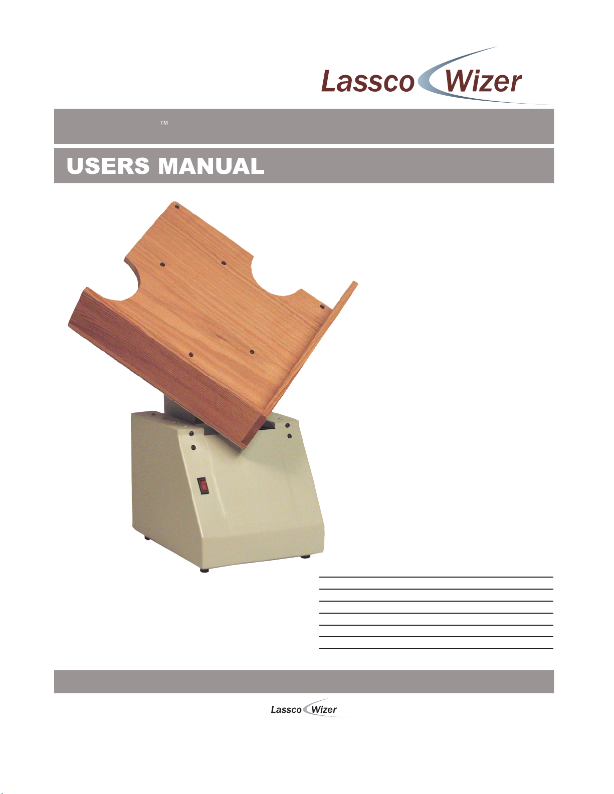
LasscoJog LJ-4 Paper Jogger
Before operating this equipment, please read these
instructions completely and keep these operating
instructions for future reference.
485 Hague Street, Rochester, NY 14606 U.S.A.
Tel: 585-436-1934 Fax: 585-464-8665
www.lasscowizer.com info@lasscowizer.com
Serial Number:
Date of Purchase:
Dealer:
Address:
Telephone Number:

Instructions
Loose Item Inventory
Please remove and inspect the following items.
L-260A: Table Assembly (1) 8-32 x 1 Flat Head Screws (4)
8-32 Stop Nut (8)
Setting Up Your Machine
Attach the Table (L-260A) to the Table Support using four (4)
8-32 x 1 Flat Head Screws, eight (8) 8-32 Stop Nuts, and
four (4) #8 Lock Washers.
Step #1
Step #2
Insert the four (4) Flat Head Screws through the front of the
Table as shown.
Place the Flat Head Screws through the holes
of the Table Support.
#8 Lock Washers (4)
Flat Head Screw
Table
Step #3
Step #4
Step #5
Step #6
Attach the first Stop Nut and tighten.
Place a Lock Washer over the screw.
Attach the second Stop Nut and tighten.
Repeat steps 3 - 5 on the remaining
screws.
Nut
Lock Washer
Nut
Table Support
Page 01

Instructions
Adjusting the Jogging Speed
To change the Jogging action:
Step #1
Step #2
Step #3
Open the back panel on the rear of the machine by
removing the two bottom screws and flipping the
cover up as shown in the rear view.
Loosen the Button Head Machine Screw and
rotate one of the Adjustment Discs attached to
the Disc Shaft extending from the motor .
Tighten down the Machine Screw.
Rear View
Note:
Side View
L-1014: Motor
FM5-5008: Electric Cord
L-1020: #6 Hose Clamp
L-1019: Torque Tube
L-1021: Shaft Collar
L-1017: Eccentric Adjustment Disc
10-32 Screw x 3/4 Button Head Machine Screw
L-1018: Eccentric Disc Shaft
3/8” ID x 3/4” OD Fiber Washer
L-1016: Clevis
L-1034: Flange Bearing
Underside View
When the screws are located opposite each other on the shaft, the minimum action is
obtained. When the screws are located on the same side of the shaft, the maximum
action is obtained. Normal action is obtained when the screws are 80 to 90 apart.
Page 02

Trouble Shooting Guide
Problem Cause Correction
Machine does not turn on. Machine is not plugged in or
there is no electricity to the outlet.
Power switch is faulty.
Motor has burned out.
The motor turns on but the
machine does not jog as
desired.
The Torque Tube (L-1019) has
worn out or broken.
The screw on the Eccentric
Adjustment Disc (L-1017) has
come loose allowing the disc to
shift.
Make sure the power cord is
connected correctly and that the
outlet is live.
Contact a service technician to
replace the power switch.
Contact a service technician to
replace the motor.
Replace the Torque Tube.
Access the Adjustment Discs and
tighten down the screw as shown
on page 1.
Page 03
 Loading...