

La Spaziale Seletron S40 Manual For Use And Maintenance
eletron
S
espresso coffee machines
MANUAL FOR USE
AND MAINTENANCE
LSC 040 - Rev. 00 - Ed. 12/2009

EC Declaration of Conformity to the Directive 97/23/EC
Pressurised Equipment Directive – PED
MANUFACTURER: La Spaziale Spa
ADDRESS: Via E. Duse, 8 - Casalecchio di Reno (BO) ITALIA
HEREBY DECLARES THAT:
On the espresso coffee machine S40 the pressure assembly is composed of a boiler complete with
safety and adjustment devices, used for rapid preparation of espresso coffee, steam and infusions.
This assembly conforms to the essential requirements of the Directive 97/23/EC
and to national
laws acknowledging it, following the conformity assessment procedure below:
- NI 9887 Regulations, ISPESL collection rev. 95
The assembly also satisfies the following EC Directive:
- 2006/42/CE - 2006/95/CE - 2004/108/CE
WEEE
Disposal of the equipment by the users
within the European Community ( WEEE) in
compliance with the article 13 of the legislative decree issued on 25 July 2005, nr151
”Implementation of the directives 2002/95/
CE,2002/96/CE e 2003/108/CE, concerning the decrease in the usage of dangerous
substances in the electrical and electronic
equipment and the disposal of waste”.
The symbol of the crossed waste bin
indicated on the equipment or on the
packaging means that the product
at the end of its lifetime must be disposed of separately from all the other
waste.
The separate collection of this equipment coming at the end of its lifetime is organized and run
by the importer/distributor.The user who should
have to dispose of such equipment should get
in touch with the importer/ distributor and follow the procedure they have adopted for the
separate disposal of the equipment coming at
the end of its lifetime.The proper separate disposal of disused equipment so that it can be
recycled and treated according what is environmentally compatible contributes to avoid possible negative effects on the Environment and
on Health and allows the reutilization and/or
the recycling of the materials the equipment is
composed of.
The improper disposal by the user causes the
enforcement of the administrative sanctions according to current regulations.
Cacciari Franca (CEO)
espresso coffee machines
1
LSC 040 - Rev. 00 - Ed. 12/2009
Behind the coffee bar counter, every seconds precious, cup after cup.
The coffee machine is the instrument which dictates the rhythm.
It has to be technological, reliable, ergonomic. It has to be attractive, fit in with the furnishings, the shades of colour, the lights.
It makes your work run smoothly. You have thus more time to think, to express your own creativity, to better fulfil the art of the barman.
In planning the new S40, La Spaziale top of the range, the technicians set themselves these goals.
They observed gestures, pauses and work spaces to come up with the ergonomic aspects.
Then, they dressed the elements of functionality with a high-class aesthetic, as elegance and practicality may blend in an excellent design. Inside the machine, they placed a technological heart, whose components interact with extreme precision, guided by avant-garde
electronics.
An ample display with LCD graphics guarantees total interaction between the barman and the
engineer responsible of maintenance, who in every single moment has full control of the
machine. There is rapid and easy access to the technological heart of the S40. Accu-
rately programmed control cycles allow to reduce maintenance time and ensure
that the machine is kept in a state of maximum efficiency.
A personalised card gives access to the management programmes,
making the S40 unique and secure in every aspect. The updates
of the software controlling the machine are extraordinarily simple.
Energy consumption is limited, as after 20 minutes of inactivity the
machine goes into “stand-by”. But this in only the start of a journey.
The opportunities offered by digital technologies are constantly
growing and the S40 is ready to seize them all.
La Spaziale S.p.A.

espresso coffee machines
2
LSC 040 - Rev. 00 - Ed. 12/2009
INDEX
1. GENERAL DESCRIPTION OF THE MACHINE ................................. 5
1.1 DESCRIPTION OF THE MAIN COMPONENTS
OF THE MACHINE .......................................................................6
1.1.1 Coffee dispensing touchpad ...........................................6
1.1.2 Control panel ................................................................... 7
1.1.3 Display principale ............................................................ 8
1.2 ORIENTATION OF THE MACHINE ............................................... 9
2. GENERAL ADVICE FOR THE INSTALLER .....................................10
2.1 GENERAL WARNINGS ...............................................................10
2.2 INSTALLATION REQUIREMENTS FOR THE USER....................12
2.1 WARNING/TECHNICAL DATA LABELS AND
NAMEPLATES APPLIED TO THE MACHINE.............................. 14
3 REMOVING THE PACKAGING ......................................................15
3.2 STANDARD EQUIPMENT OF THE MACHINE ............................ 16
3.3 OPTIONAL ACCESSORIES
(SUPPLIED ONLy AT THE REQUEST OF THE CUSTOMER)
.............................17
4. COMMISSIONING THE MACHINE ................................................. 18
5 SWITCHING ON THE MACHINE .................................................... 19
5.1 FILLING UP WITH WATER .........................................................20
5.1.1 Water level indicator of the boiler ..................................20
5.2 APPLIANCE HEATING AND PREPARATION STAGE .................22
5.3 COFFEE PREPARATION ............................................................ 24
5.4 STEAM DELIVERY ...................................................................... 27
5.5 DELIVERING WATER TO PREPARE INFUSIONS .......................28
5.5.1 Semiautomatic mode .................................................... 29
5.5.2 Automatic mode ............................................................ 29
5.6 AUTOMATIC MILK EMULSION WITH
TEMPERATURE ADJUSTMENT - M.A.T. (OPTIONAL) ............... 30
5.7 BOOST FUNCTION .................................................................... 32
5.7.1 Economy FUNCTION .................................................... 34
5.8 FUNCTION OF THE THERMOSTAT-REGULATED
CUP WARMER SURFACE ..........................................................35
6. CLIENT PARAMETER PROGRAM ACCESS .................................. 36
6.1 TIMER .........................................................................................38
6.1.1 Daily programming ........................................................ 40
6.1.2 Weekly programming .................................................... 41
6.1.3 Timer active ................................................................... 42
6.2 LED
S
........................................................................................... 43
6.3 CALENDAR ................................................................................ 45
6.4 LANGUAGE ................................................................................ 47
6.5 INFO ...........................................................................................48
6.5.1 Serial number ................................................................ 49
6.5.2 Software release ............................................................50
6.6 BEEP .......................................................................................... 51
6.7 COUNTER .................................................................................. 52
6.7.1 Reset counter ................................................................55
6.8 GRINDING CONTROL ................................................................56
6.9 LOGO ......................................................................................... 58
6.10 CLEANING ................................................................................. 59
6.11 EGS ............................................................................................63
6.12 SCREENSAVER .......................................................................... 65
7. SOFTWARE UPDATING .................................................................. 67
8. ROUTINE APPLIANCE MAINTENANCE
TO BE PERFORMED BY THE USER .............................................. 70
8.1 DAILY AT THE END OF THE JOB ............................................... 70
8.2 EVERY TWO WEEKS .................................................................. 72
9. LIST OF PROGRAMMABLE FUNCTIONS
(TECHNICAL ASSISTANCE SERVICE ONLY) ................................. 73
espresso coffee machines
3
LSC 040 - Rev. 00 - Ed. 12/2009
10. MANAGEMENT OF THE ALARMS ................................................. 78
10.1 ALARM MESSAGES VISUALISED
ON THE MAIN DISPLAy .............................................................78
10.2 ALARM MESSAGES VISUALISED
ON THE FRONT DISPLAy ..........................................................78
10.2.1 Alarms relative to the auto-level system ......................79
10.3 MESSAGES VISUALISED ON THE COFFEE DISPENSING
GROUPS’ DISPLAyS ................................................................ 87
11. TECHNICAL DATA ........................................................................... 89

espresso coffee machines
4
LSC 040 - Rev. 00 - Ed. 12/2009
espresso coffee machines
5
LSC 040 - Rev. 00 - Ed. 12/2009
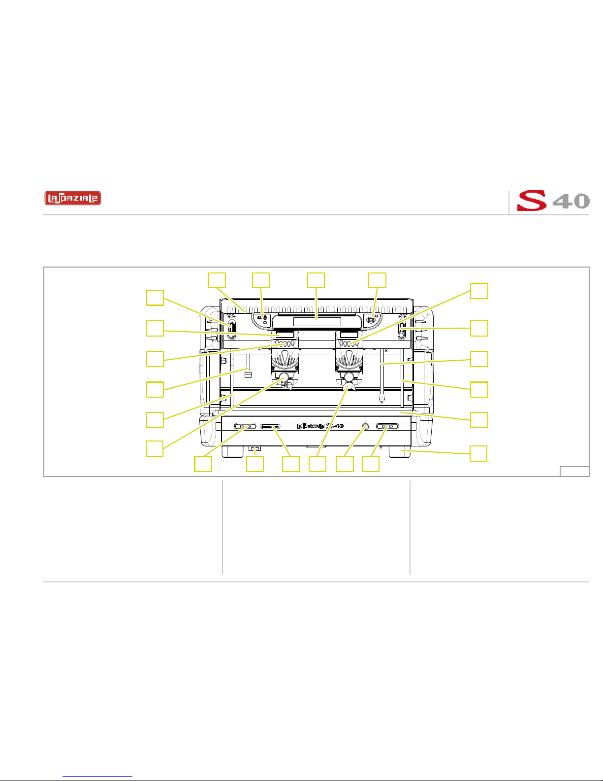
1. GENERAL DESCRIPTION OF THE MACHINE
The S40 coffee machine is designed and manufactured by LA SPAZIALE S.p.A. to increase the profitability of the buffet bar service by
reducing operating costs to the minimum.
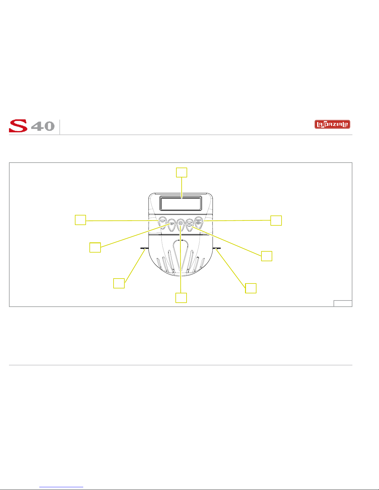
LEGEND
1. Selector touchpad
2. Main display
3. Navigation touchpad
4. Coffee dispensing group 1 touchpad
5. Right steam tap
6. Steam wand with incorporated tem-
perature sensor (M.A.T.) (optional)
7. Right steam wand
8. Water collection basin + grill
9. Adjustable foot
10. M.A.T. dispensing system touchpad
(optional)
11. Main on/off switch
12. Two-cup filter holder
13. Card reader
14. SD/MMC card reader
15. Water supply touchpad for infusions
16. One-cup filter holder
17. Left steam wand
18. Water supply wand for infusions
19. Coffee dispensing group 2 touchpad
20. Coffee dispensing group display
21. Left steam tap
22. Cup warmer plate
Fig. 1
122 2 3
00
1011121315
21
20 5
4
619
718
817
9
16
14
espresso coffee machines
6
LSC 040 - Rev. 00 - Ed. 12/2009
1.1 DESCRIPTION OF THE MAIN COMPONENTS OF THE MACHINE
1.1.1 Coffee dispensing touchpad
LEGEND
1. Display
2. 2 long coffees’ key
3. 2 short coffees’ key
4. Work surface illumination LED
5. Continuous delivery key
6. 1 long coffee key
7. 1 short coffee key
Fig. 2
1
5
7
6
2
3
4
4
espresso coffee machines
7
LSC 040 - Rev. 00 - Ed. 12/2009
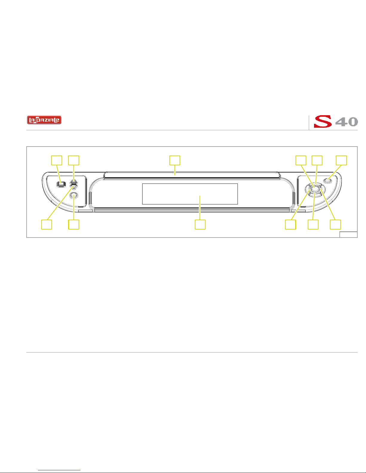
1.1.2 Control panel
LEGEND
1. Cup warmer heating plate on/off key
2. Cup warmer heating plate temperature increase key
3. Logo
4. OK key
5. Scroll up arrow key
6. Stand-by/on key
7. Scroll right arrow key
8. Scroll down arrow key
9. Scroll left arrow key
10. Main display
11. On/off manual boost key
12. Cup warmer heating plate temperature decrease key
Fig. 3
321 4 5 6
12 11 10 9 8 7
espresso coffee machines
8
LSC 040 - Rev. 00 - Ed. 12/2009
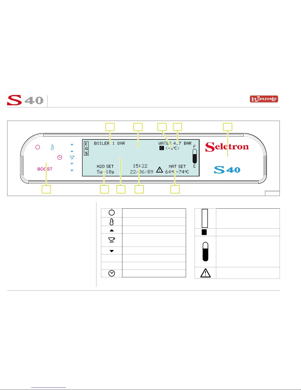
1.1.3 Display principale
ECO
120° C
LEGEND
1. Boiler pressure
2.
Boiler temperature
3. Compensation temperature
4. Water supply or motor pump pressure
5. Series and model of the machine
6. M.A.T. temperature setting programme
system (optional)
7. Hour and date
8. Message area
9. Hot water dispensing times setting
programme for infusions
10. Signal symbols
SYMBOLS
Stand-by
Automatic level “ON”
Temperature increase signal
Cup warmer resistances
“ON”
Temperature decrease signal
ECO
Economy function activated
BOOST
Boost function activated
Timer function “ON”
E
G
S
EGS function “ON”
C
Compensation function “ON”
F
E
Level indicator
”Alarms active” indicator
Fig. 4
1 2 3 4 5
10 789 6
espresso coffee machines
9
LSC 040 - Rev. 00 - Ed. 12/2009
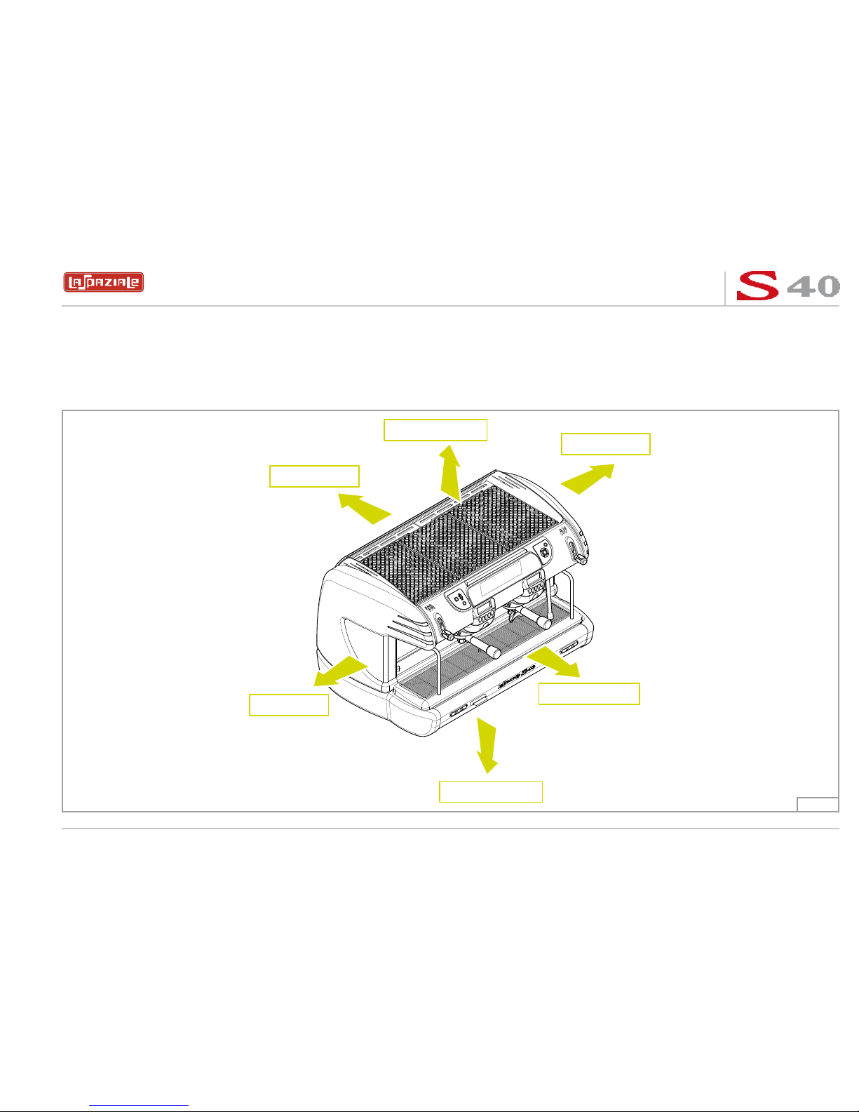
1.2 ORIENTATION OF THE MACHINE
To ensure that each reference to the various parts of the machine (front, rear, etc.) that appear in this manual is clear and unmistakable,
the orientation of the machine is as represented in this figure.
Any exceptions to this rule will be specified.
UPPER PART
LOWER PART
FRONT PART
REAR PART
RIGHT SIDE
LEFT SIDE
Fig. 5

espresso coffee machines
10
LSC 040 - Rev. 00 - Ed. 12/2009
2. GENERAL ADVICE FOR THE INSTALLER
Read carefully the instructions and warnings contained in this manual and in the “INSTRUCTION MANUAL FOR THE INSTALLER”,
since they provide important indications concerning the installation of the appliance.
Attention!
CAREFULLY READ THE FOLLOWING WARNINGS, WHICH OFFER IMPORTANT GUIDELINES FOR THE SAFE USE AND
MAINTENANCE OF THE APPLIANCE.
The appliance must only be used for its intended purpose and it must be installed in a suitable place for its use. Any other use is therefore considered as improper and unreasonable.
The manufacturer cannot be held liable for any damage caused by improper, incorrect or unreasonable use. Installation must be carried
out by qualified personnel according to current laws and to the manufacturer’s instructions. Incorrect installation may cause damage to
people, animals or property for which the manufacturer cannot be held liable.
Attention!
The electric system, water system and drainage system MUST BE put in place by the customer in a suitable position to allow
correct installation. The installation engineer cannot change the existing system put in place by the customer. See chapter 2.2:
“Arrangements for installation provided by the customer”.
Attention!
The appliance must be installed where use and maintenance are restricted to trained staff.
2.1 GENERAL WARNINGS
espresso coffee machines
11
LSC 040 - Rev. 00 - Ed. 12/2009
Danger!
The electrical safety of the appliance is fully achieved only after it has been correctly connected to an earthing system as
required by the laws in force.
It is necessary to have the earthing connection checked by professionally qualified personnel. The manufacturer cannot be held liable
for any damage caused by the lack or inefficiency of the system’s earthing connection. The appliance has not been designed for outdoor
use. It must only be operated in a place where the ambient temperature is between
+5°C
and
+40°C
.
Attention!
The use of any electrical appliance also requires observance of the following important regulations.
• Do not touch the appliance with wet or damp hands or feet.
• Do not use the appliance barefooted.
• Do not pull the power supply cord to unplug the appliance from the mains power.
• Do not allow children or unqualified persons to use the appliance.
• Access to the appliance’s service area must be restricted to those persons with the relevant practical experience and familiarity with
the appliance itself, especially in terms of safety and hygiene.
• Before carrying out any routine maintenance or cleaning operation, disconnect the appliance from the mains power and shut off the
water supply tap.
• In the event of damage and/or malfunction of the appliance, switch it off completely without trying to make any direct repairs. Contact
the nearest Service Centre authorised by the manufacturer.
• In order to guarantee the proper efficiency and operation of the appliance, it is fundamentally important to follow the manufacturer’s
instructions, and to follow a regular maintenance schedule.
• The appliance has IPX2 protection against water and therefore, it cannot be installed in areas where it may be subject to jets of water.
• The appliance has class I protection against electric shocks.
• The noise emitted by the appliance during normal operation is less than 70 dB.
espresso coffee machines
12
LSC 040 - Rev. 00 - Ed. 12/2009
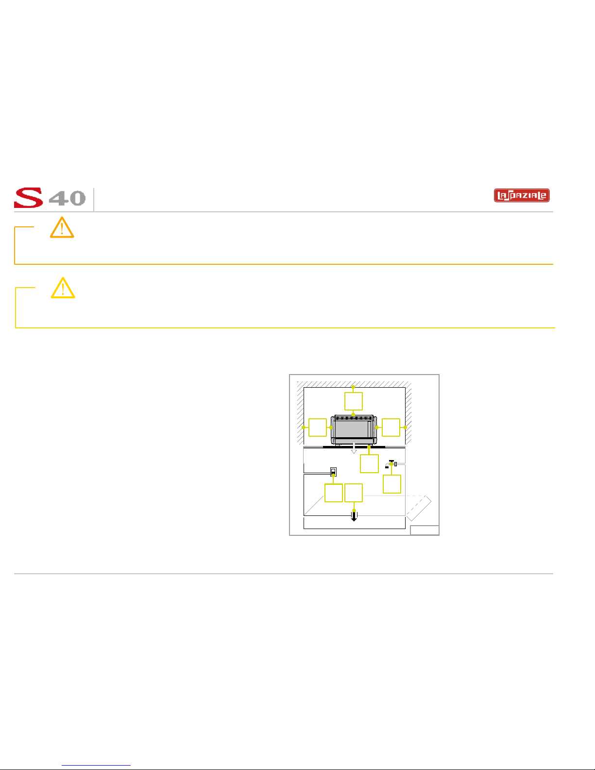
2.2 INSTALLATION REQUIREMENTS FOR THE USER
The machine has to be placed on a stable flat surface that can
guarantee a safe position. Check this important requirement,
since the manufacturer cannot be considered liable for any damage caused by the instability of the appliance. While preparing
the systems, take into account that a hole is needed in the bearing surface in order to make all electric and water connections
through the opening below where a water softener will need to be
fitted, if recommended by the installation engineer.
A hole of
10 x 10 cm
is enough in the area (a) as indicated in
Pict. 6.
The machine needs a minimum clearance of:
- height cm. 60
- width cm. 40
- depth cm. 40
Warning!
The appliance is supplied without a plug. It is supposed to be directly connected to the electric mains and therefore, it is
necessary to fit a single-pole switch with contact opening of 3 mm or more beforehand, according to the regulations in force .
Attention!
Failure to comply with the above regulations could jeopardise the correct operation and safety of the appliance as well as its
useful lifetime.
Y
XX
A
2
1
3
Fig. 6
Legend:
1 Single pole switch
with an opening of at
least 3 mm between
contacts
2 Water supply tap
3 Drain siphon
X min. 20 cm.
Y min. 40 cm.
Z* min. 10 cm.
*) Distance between the
back of the appliance
and the wall.
espresso coffee machines
13
LSC 040 - Rev. 00 - Ed. 12/2009
• Between the water mains and the water inlet pipe of the appliance, there must be a tap to stop the water flow if necessary (2 - Pict.6).
• The water mains pressure must be within the range of 1 and 5 bar.
• If this requirement is not met, please consult the manufacturer.
• The appliance is supplied without a plug. It is supposed to be directly connected to the electric mains and therefore, it is necessary
to fit a single-pole switch with contact opening of 3 mm or more beforehand, according to the regulations in force (1 - Pict.6).
• The drainpipe of the appliance must be directly connected to a suitable open drain siphon, previously installed by the customer (3
- Pict.6). Do not fit the drain pipe into basins or buckets placed under the counter as this will increase the possibility of forming dirt
deposits and as a result, the spread of bacteria.
Attention!
The appliance is supplied without water in the boiler. This is to prevent serious damage if the appliance is exposed to low
temperatures. The appliance must only be supplied with cold drinking water.
espresso coffee machines
14
LSC 040 - Rev. 00 - Ed. 12/2009
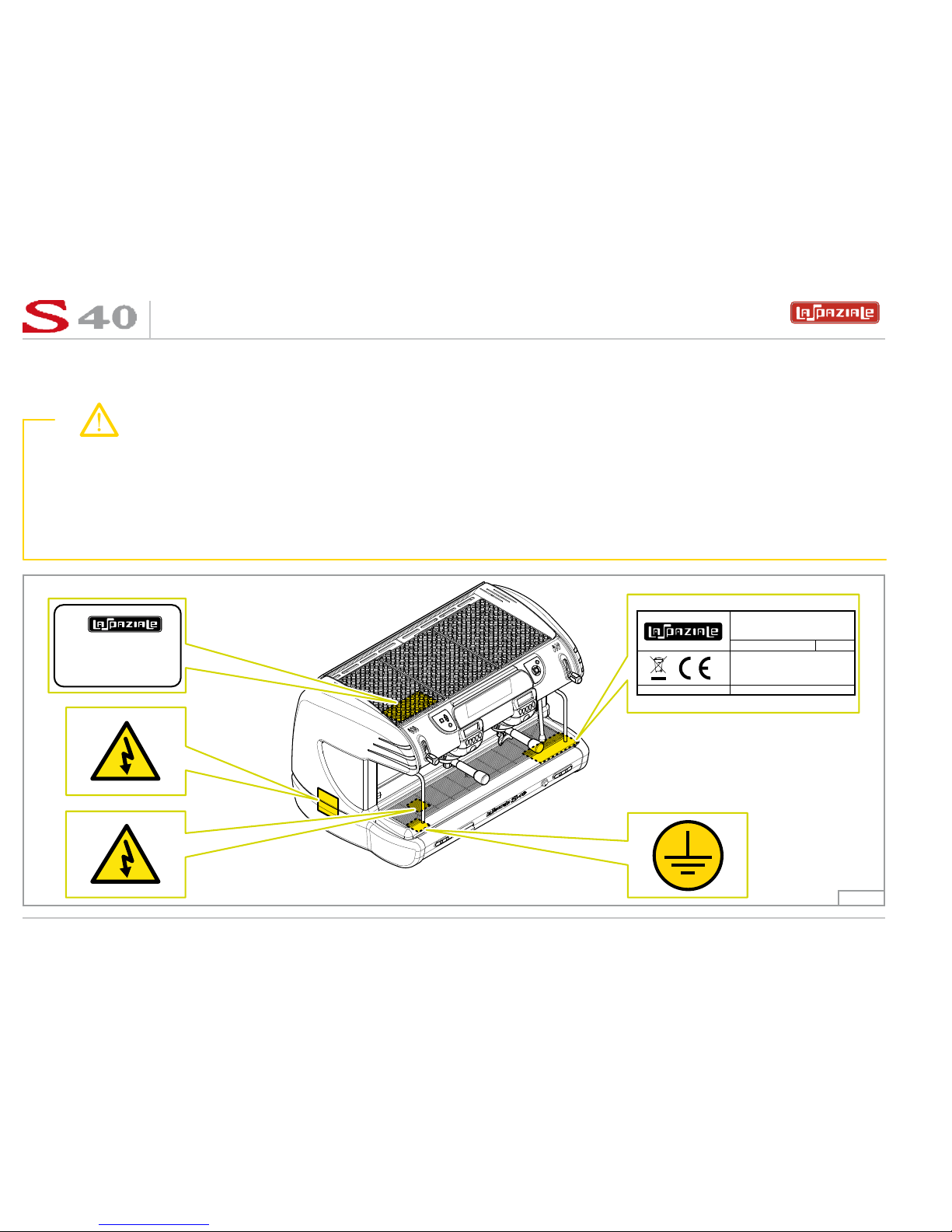
2.3 WARNING/TECHNICAL DATA LABELS AND NAMEPLATES APPLIED TO THE MACHINE.
In the figure below are shown the warning/technical data labels and nameplates positioned on the machine.
Warning!
Dedicate the time necessary to familiarise yourself with these labels.
Ensure that they are readable and keep them clean or replace those that have deteriorated or illegible (both the text and the
graphics).
Use a soft cloth, soap and water to clean the labels. Do not use solvents, petrol, etc.
If a label is positioned on a component part that has to be replaced, ensure that the new component has the same label applied or a new one.
N.F. 255600
La Sp aziale S.p.A.
Espress o mach ines
via E. Duse, 8
40033 Casalecchio di Reno BOLOGNA
N.F.
SERIES: S40 - MOD. SELETRON
VOLT 230 ~ /400 SN~ Hz 50/60
WATT 6500 IPX2
2009
- MADE IN ITALY ( UCIMAC )
BOILER: Lt. 9,30 0.15 MPa
PS 0 .6 M Pa M AX
Fig. 7
espresso coffee machines
15
LSC 040 - Rev. 00 - Ed. 12/2009
3 REMOVING THE PACKAGING
After unpacking the machine, please check its integrity; in case of doubt, do not use it and consult themanufacturer.
Packaging materials must not be left within children’s reach since they are potentiallydangerous.
Attention!
The appliance weight is more than 30 kg and therefore, it cannot be moved by a single person alone.
Take note!
Dispose of the packaging as per the norms in force of the country in which the machine is utilised.
espresso coffee machines
16
LSC 040 - Rev. 00 - Ed. 12/2009
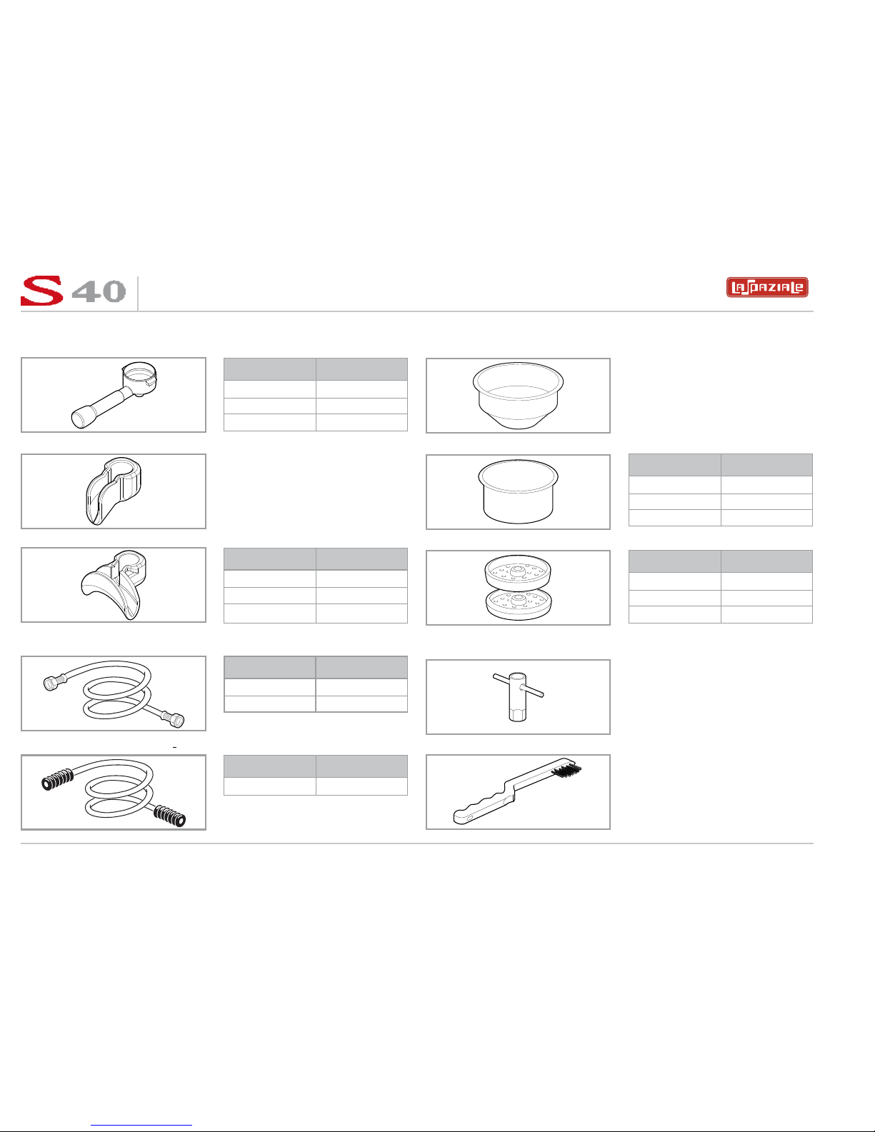
3.2 STANDARD EQUIPMENT OF THE MACHINE
FILTER HOLDER
1 CUP SPOUT
2 CUP SPOUT
CONNECTION
WATER SUPPLY HOSES
DRAINAGE HOSES
GROUPS UNIT
2 x 3
3 x 4
4 x 5
x 1
GROUPS UNIT
2 x 2
3 x 3
4 x 4
QUANTITY
LENGHT
1 150 cm
1 70 cm
QUANTITY
LENGHT
1 150 cm
1 CUP FILTERS
2 CUP FILTERS
1 SET OF SHOWER HEADS
1 BOX SPANNER FOR
SHOWER HEAD REMOVAL
BRUSH
x 2
GROUPS UNIT
2 x 4
3 x 6
4 x 8
GROUPS UNIT
2 x 2
3 x 3
4 x 4
x 1
x 1
espresso coffee machines
17
LSC 040 - Rev. 00 - Ed. 12/2009
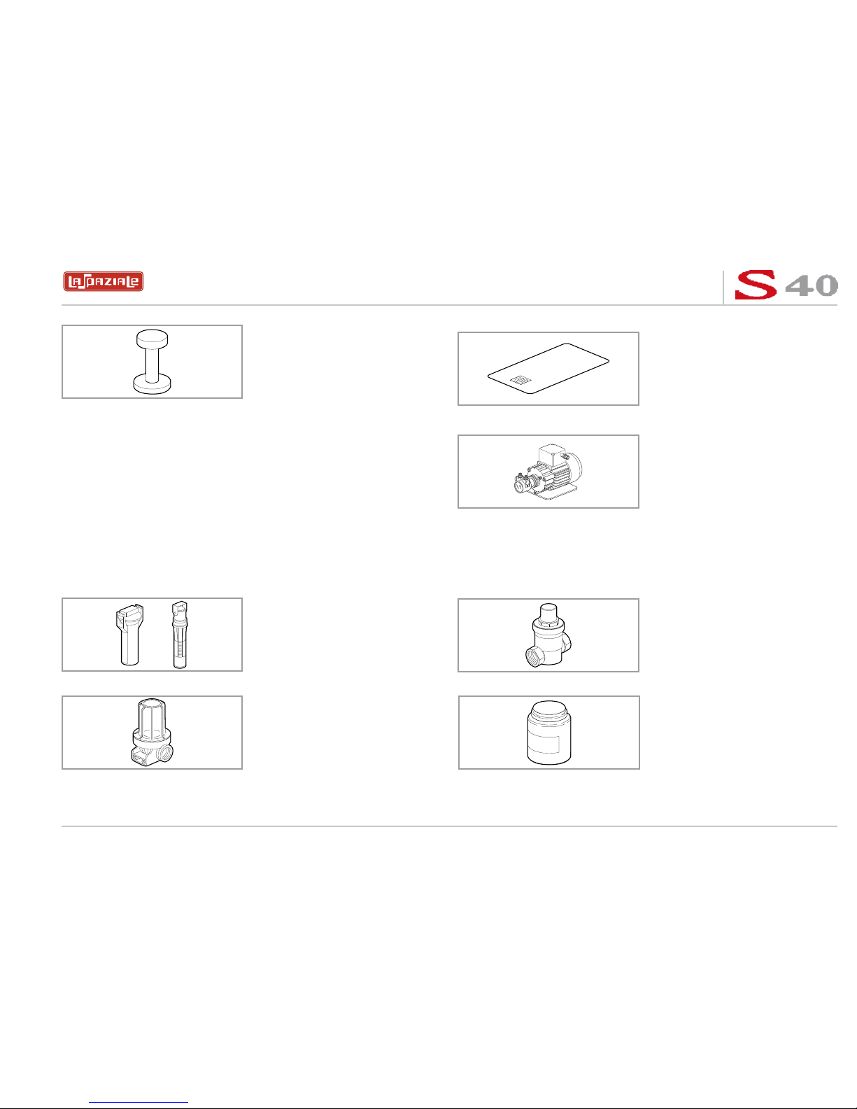
MANUAL COFFEE TAMPER
x 1
CUSTOMER CARD
MOTOR POMP
x 1
x 1
3.3 OPTIONAL ACCESSORIES
(Supplied only at the request of the customer)
WATER SOFTENER
FILTER
x 1
x 1
PRESSURE REDUCER
DETERGENT
x 1
x 1
(When the pump is
not incorporated in
the machine)

espresso coffee machines
18
LSC 040 - Rev. 00 - Ed. 12/2009
4. COMMISSIONING THE MACHINE
a) Open the water supply valve as envisaged in the preparations for installation (
See
Fig. 6 on page 12 - Ref. 2
).
b) Check for any water leaks from the hosing/connections.
c) Switch on the main breaker as envisaged in the preparations for installation (
See
Fig. 6 on page 12 - Ref. 1
).

espresso coffee machines
19
LSC 040 - Rev. 00 - Ed. 12/2009
espresso coffee machines
19
LSC 040 - Rev. 00 - Ed. 11/2009
120° C
120° C
_
+
_
+
Fig. 8
Fig. 9
Fig. 10
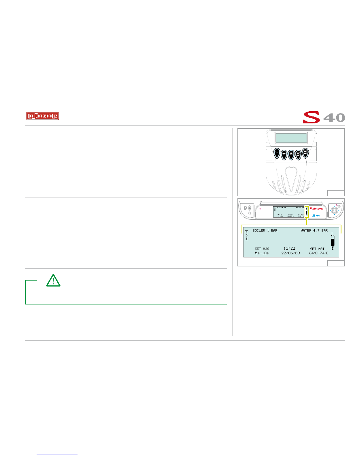
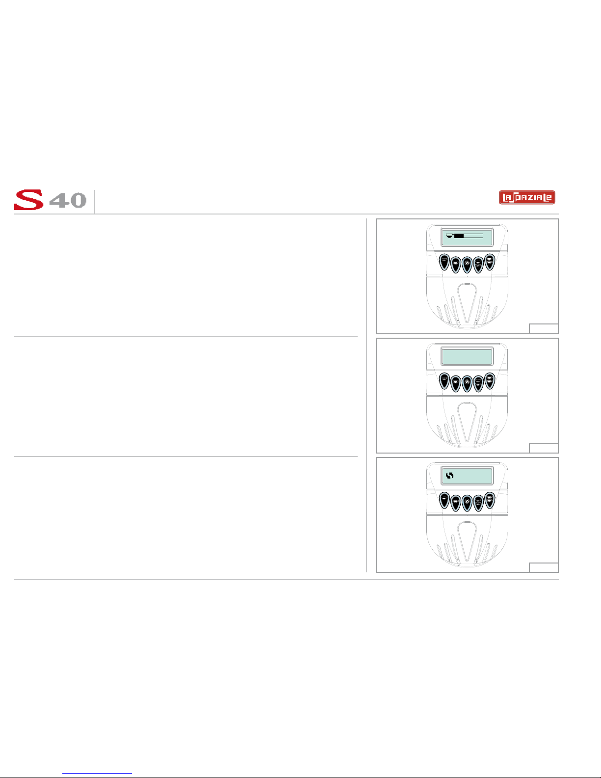
5 SWITCHING ON THE MACHINE
1. Move the switch positioned on the lower panel of the machine to the “I” position.
2. The machine goes into STAND-BY mode and the warning lights (represented in
the figure on the right) on the control panel come on (the
symbol flashes).
3. Keep the stand-by key pressed for three seconds; a general check is carried out
during which all symbols on the control panel light up without flashing for two
seconds and the main display is subsequently visualised as shown in the figure.
Take note!
All functions that were active at the moment of switching off the machine the
last time are memorised for the subsequent switching on of the machine.
espresso coffee machines
20
LSC 040 - Rev. 00 - Ed. 12/2009
5.1 FILLING UP WITH WATER
Three seconds after switching on, the machine automatically fills the boiler with water
(Fig. 11).
_
+
120° C
120° C
120° C
_
+
Fig. 11
Fig. 12
When the boiler filling phase is finished, the relative filling warning light switches off
and then a check/adjustment of the motor pump must be carried out.
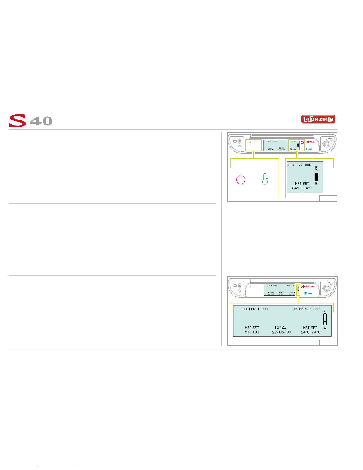
5.1.1 Water level indicator of the boiler
The level indicator positioned on the right of the main display indicates the level of
water in the boiler.
- EMPTY INDICATOR
When the level of water in the boiler has not reached the minimum level to ensure the
functioning of the machine, the level indicator symbol is shown as in the figure on the
right.

espresso coffee machines
21
LSC 040 - Rev. 00 - Ed. 12/2009
- LEVEL “1” REACHED
The
F
E
symbol is visualised when the level of water in the boiler has reached the
minimum level to ensure the functioning of the machine, but not at the level preestablished by the manufacturer.
- LEVEL “2” REACHED
The
F
E
symbol is visualised when the level of water in the boiler has reached the level
pre-established by the manufacturer.
- FULL INDICATOR
The
F
E
symbol is visualised when the level of water in the boiler has reached an exces-
sive level that does not ensure the correct functioning of the machine.
120° C
120° C
_
+
120° C
120° C
_
+
120° C
120° C
_
+
Fig. 13
Fig. 14
Fig. 15
espresso coffee machines
22
LSC 040 - Rev. 00 - Ed. 12/2009
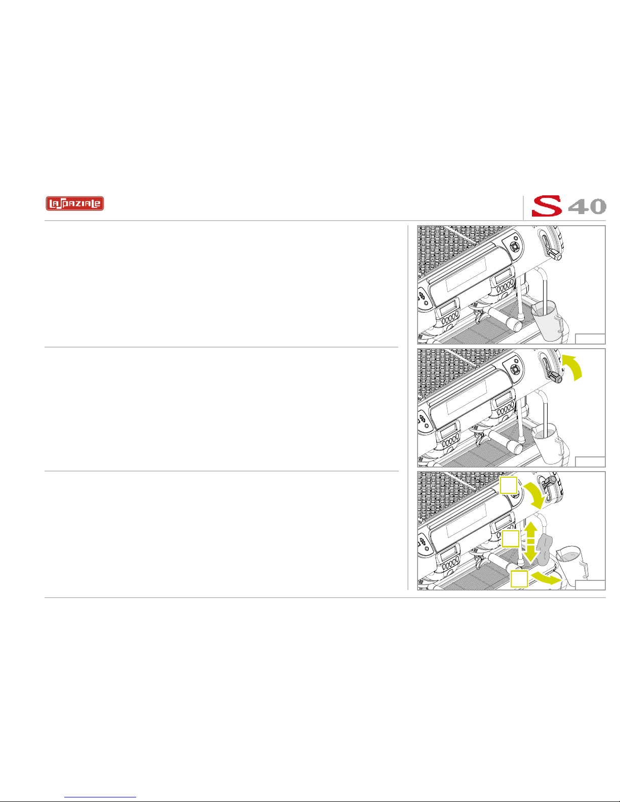
1. Attach the filter holders to the delivery groups.
1
1
2
2
1
2
2
1
1
1
2
2
Fig. 16
Fig. 17
Fig. 18
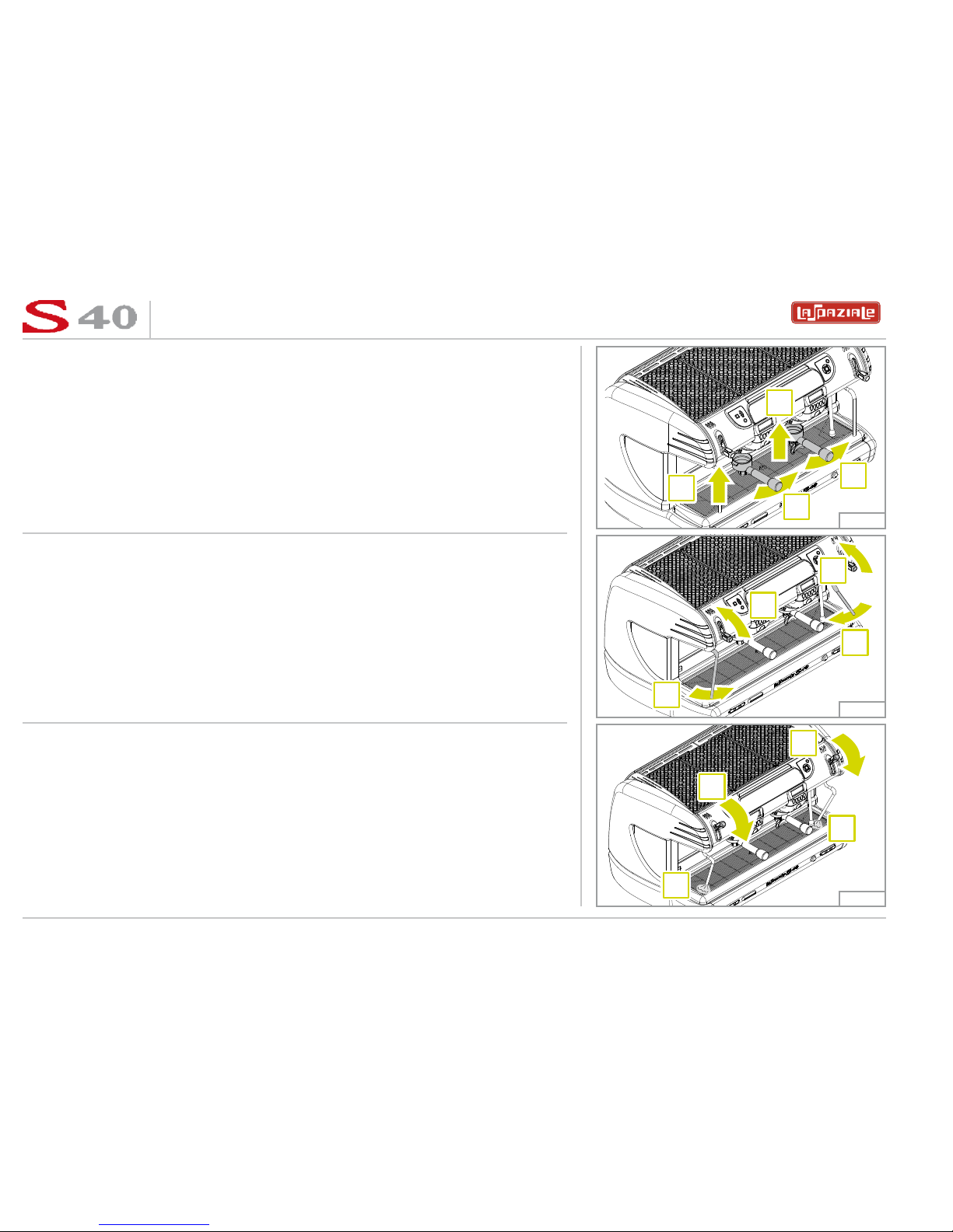
5.2 APPLIANCE HEATING AND PREPARATION STAGE
2. Open the steam delivery valves by moving the dial upwards and leave them open:
then move the steam wands over the grille.
3. Wait for steam to come out of the relevant wands (approx, 15-20 minutes) then
close the steam valves by returning the dial to the initial position.
espresso coffee machines
23
LSC 040 - Rev. 00 - Ed. 12/2009
4. Wait for the appliance to reach the running temperature.
The groups display will show the screen opposite.
SELECT DOSE
STOR
24.5 s PREV
10.8 s
120° C
BOILER HEATING
118° C
BOILER HEATING
_
+
Fig. 19
Fig. 20
Each time that the temperature inside the boiler drops to below the SET LEVEL, the
main display will show the screen opposite.
5. The appliance is ready to use.
Take note!
The running temperature is the temperature of the boiler during normal
operation.
espresso coffee machines
24
LSC 040 - Rev. 00 - Ed. 12/2009
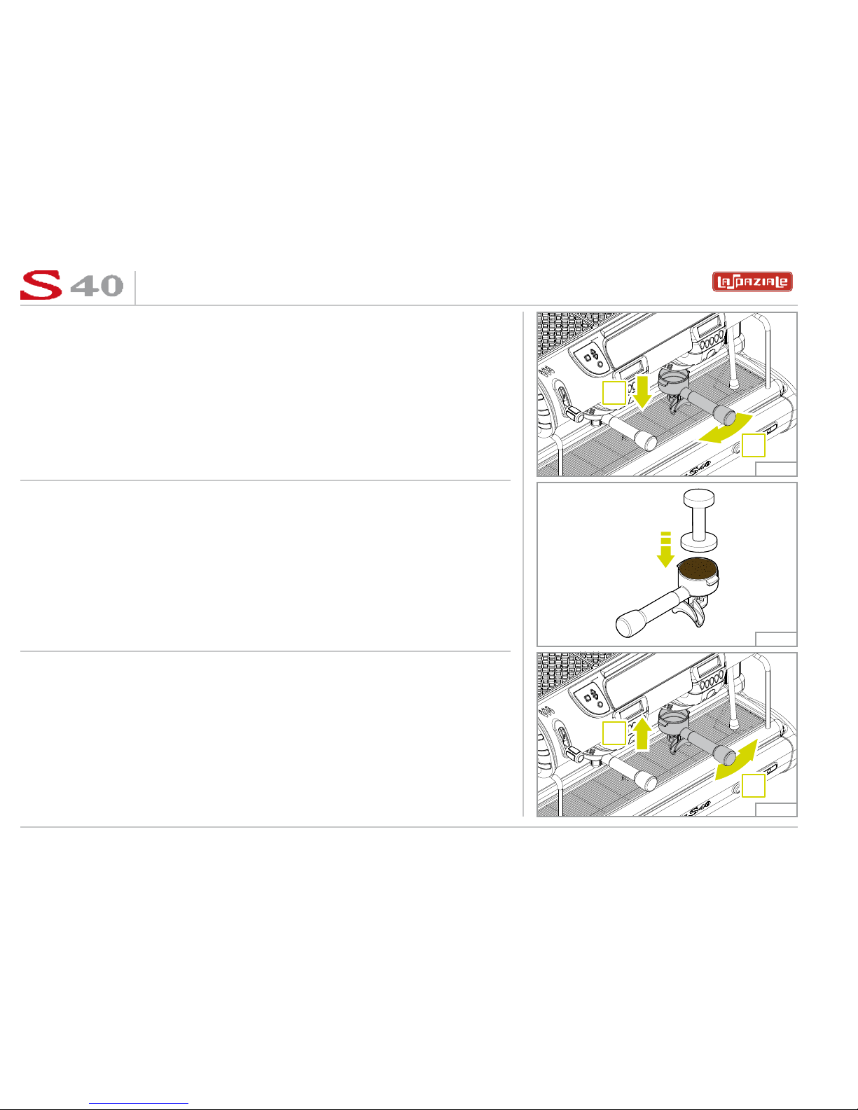
1. Remove a filter holder from the delivery group.
1
2
2
1
Fig. 21
Fig. 22
Fig. 23
5.3 COFFEE PREPARATION
2. Fill with ground coffee, taking care not to leave any coffee powder residues on the
top edge of the filter holder, then press it using the special coffee press supplied.
3. Re-insert the filter holder firmly but not excessively.
espresso coffee machines
25
LSC 040 - Rev. 00 - Ed. 12/2009
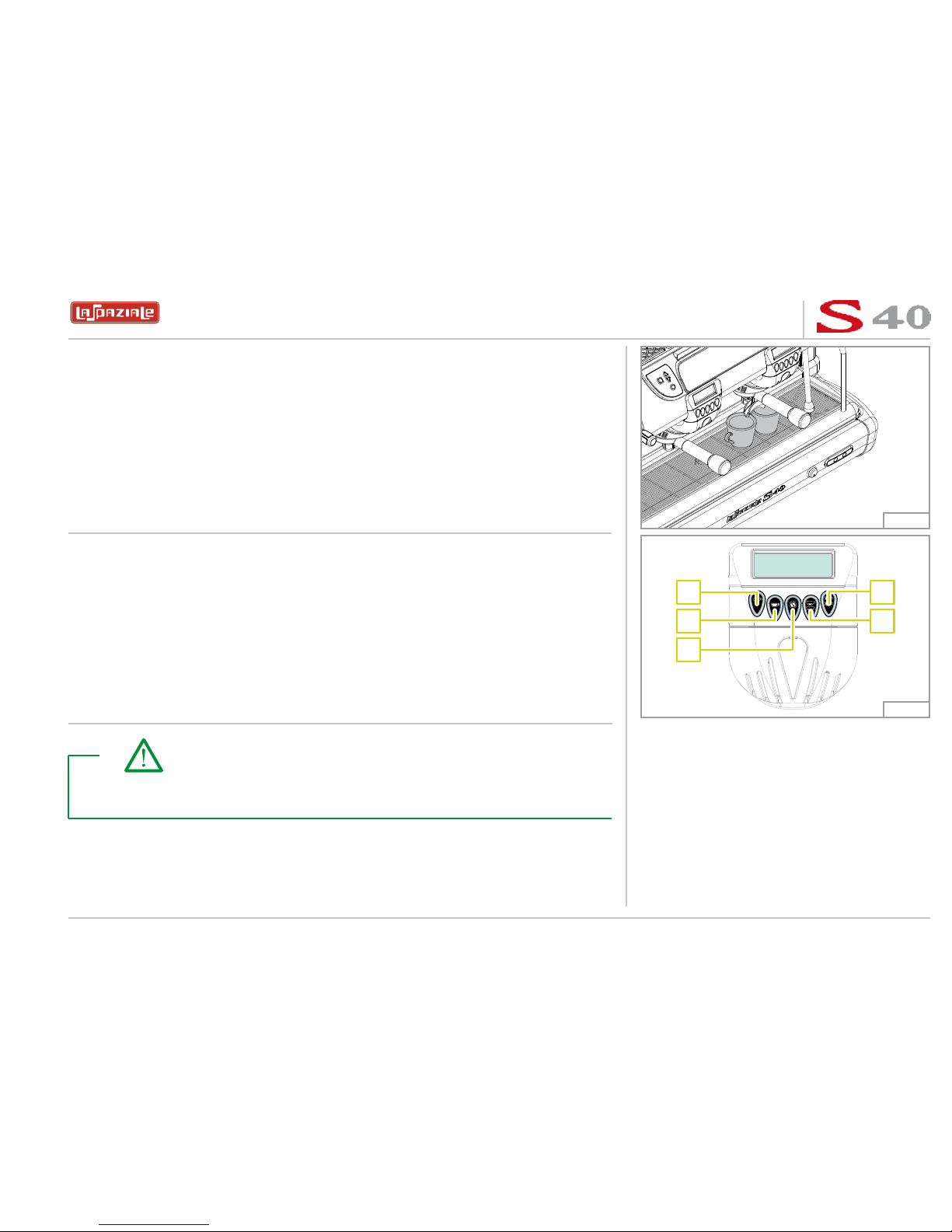
4. Place one or two cups under the filter holder (according to whether you wish to
pour 1 or 2 cups of coffee).
A
B
C
E
D
Fig. 24
Fig. 25
5. Press one of the delivery buttons (A - B - D - E) with programmed doses (during
installation) or alternatively, use the button (C) for free flow delivery.
Take note!
To stop a delivery commenced using one of the programmed dose buttons,
press the (C) key on the same touchpad.
espresso coffee machines
26
LSC 040 - Rev. 00 - Ed. 12/2009
While delivering the coffee, the group display shows the screen opposite.
Represents the icon for the selected coffee dose with alongside, a bar to show the
delivery progress.
The seconds stored during the dose programming stage for the selected dose (
MEM
)
are shown under the bar, while alongside are the seconds indicating the actual
progress of delivery (
DEL
).
STOR
24.5 s PREV
10.8 s
8,4s
DELIVERY
SELECT DOSE
STOR
24.5 s PREV
10.8 s
Fig. 26
Fig. 27
Fig. 28
Once delivery has finished, the group display will show the screen opposite.
The bottom of the display shows the seconds stored during the dose programming
stage for the last dose selected (
MEM
) and alongside, the duration, in seconds, of the
last dose delivered (
PREV
).
During free flow coffee delivery, the group display will show the time of the ongoing
delivery in seconds.
espresso coffee machines
27
LSC 040 - Rev. 00 - Ed. 12/2009
1. Insert the steam wand into a jug containing the beverage to be heated.
1
3
2
Fig. 29
Fig. 30
Fig. 31
5.4 STEAM DELIVERY
2. Move the dial of the corresponding steam wand upwards. Adjust the steam flow
as required.
3. When the beverage is sufficiently hot, shut off the steam by moving the dial to
its original position, remove the jug away from the steam wand and wipe off any
residues immediately using a damp sponge.
 Loading...