

La Spaziale S1 Vivaldi II Owner's Manual
La Spaziale S1 Vivaldi II
Double Boiler Espresso Machine
Owner’s Manual
(Covers VII’s with and w/o Enhanced Temperature Offset and Programmable Preinfusion)
Added Information on adjusting steam pressure
10/11/2015

S1 Vivaldi II Owner’s Manual
Page 1
Table of Contents
1! Feature Overview ..................................................................................................... 3!
2! Reference Photos ..................................................................................................... 3!
3! Document Scope – Caveats and Clarifications ........................................................ 5!
4! Basic Machine Operation ......................................................................................... 5!
4.1! 15A or 20 Amp Operation .................................................................................. 5!
4.2! Optional On/Off Timer Accessory – Overview and WARNING ........................ 7!
4.3! Initial Installation Before Connecting Power ...................................................... 8!
4.4! Turning On and Heating the Machine ............................................................... 9!
4.5! Espresso Brewing ............................................................................................. 9!
4.6! Volumetric Dose Programming ....................................................................... 10!
4.7! Hot Water Delivery .......................................................................................... 10!
4.8! Steam Delivery ................................................................................................ 10!
4.9! Economy / Boiler Operational Modes .............................................................. 11!
4.10! V1/VII Mode Switch ......................................................................................... 12!
4.11!Espresso Group Water Temperature Regulation
......................................... 12!
4.11.1! Standard Temperature Adjustment .......................................................... 12!
4.11.2! Offset Temperature Adjustment ............................................................... 13!
4.11.3! Steam Pressure Adjustment .................................................................... 15!
4.11.4! Extreme Temperature Set Function ......................................................... 16!
4.12! Programmable Preinfusion .............................................................................. 17!
5! Alarm Handling ....................................................................................................... 18!
5.1! Coffee Group Water Dosing System Failure ................................................... 18!
5.2! Coffee Group Temperature Detection System Failure .................................... 18!
5.3! Steam Boiler Temperature Detection System Failure ..................................... 18!
5.4! Damaged Group Heating Element Triac (SSR) .............................................. 18!
5.5! Damaged Boiler Heating Element Triac (SSR) ............................................... 19!
5.6! Boiler Automatic Refill System Failure ............................................................ 19!
6! Connection Diagrams ............................................................................................. 20!
6.1! Electrical Connection Diagram ........................................................................ 20!
6.2! Control Board Connection Diagram ................................................................ 21!
6.3! Triac Board Connection Diagram .................................................................... 21!
6.4! Control Panel Connection Diagram ................................................................. 22!
6.5! Wiring Diagram Definitions .............................................................................. 22!
7! VII Water Flow Diagram ......................................................................................... 23!
8! Adjustments and Maintenance ............................................................................... 24!
8.1! External VII Surface Cleaning ......................................................................... 24!
8.2! Routine Group Cleaning .................................................................................. 24!
8.3! Group Pressure Test and Adjustment ............................................................ 25!
8.4! Expansion Valve Release Adjustment ............................................................ 26!
9! Optional Accessories .............................................................................................. 27!
10! Other LaSpaziale VII Resources ............................................................................ 30!

S1 Vivaldi II Owner’s Manual
Page 2
11! Quick Setting Guide ................................................................................................ 31!

S1 Vivaldi II Owner’s Manual
Page 3
1 Feature Overview
! Dual Boiler
! Steam Boiler 2.5 liter
! Steam Boiler Element 1250 Watts
! Group Boiler .45 liter
! Group Boiler Element 800 Watts
! Direct Plumbed
! Rotary Pump
! Volumetric Dosing Adjustable Through Touch Pad
! Group Temperature Indicated by lamp Display
! Group Temperature Adjustable in 1°C Increments Through Touch Pad
! New and Upgraded machines since 7/1/2008 include Extended Temperature Offset
Adjustment and Programmable Preinfusion
! Electronic Boiler Refill
! Built in Safety Thermostat
! Semi Automatic Hot Water Delivery
! Manual Steam Valve
! Fault Diagnosis Alarms
! Combined Boiler and Group Pressure Gauge
! Two Complete Portafilter handles - Single and Double Baskets
! Extra shower screens, removal wrench, cleaning brush, tamper
! Includes rubber back flush disk
! OPTIONAL Pre Infusion Chamber
! OPTIONAL 7 Day Programmable Timer
! OPTIONAL No Burn Steam Arm
! OPTIONAL longer La Spaziale steam arm
! OPTIONAL Drain Kit
! Color Black, Silver, or Red
! 110 volt
! Available in either 15 amp or 20 amp
! ETL Sanitation Listed (Conforms to ANSI/NSF STD 4)
! c ETL us Listed (Conforms to UL STD 197 Certified to CAN/CSA STD C22.2 NO. 109
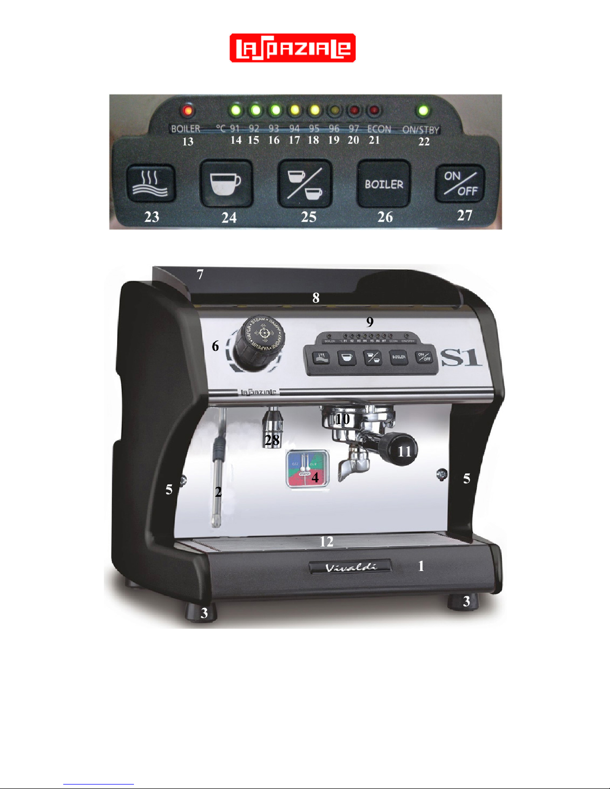
2 Reference Photos
These numbered photos will be referenced throughout the document; i.e. (13)
S1 Vivaldi II Owner’s Manual
Page 4
FIGURE 1 – Indicator Lights and Control Buttons
S1 Vivaldi II Owner’s Manual
Page 5
Label
Function
Label
Function
Label
Function
Label
Function
1
Drip Tray
8
Cup Warming
Tray
15
92°C Lamp
22
On/Standby
Lamp
2
Steam Arm
9
Control Panel
16
93°C Lamp
23
Hot Water Button
3
Rubber Feet
10
Group
17
94°C Lamp
24
Single Cup
Button
4
Steam/Group Pressure
Gauge
11
Portafilter Handle
18
95°C Lamp
25
Double Cup
Button
5
Side Panels
12
Drip Tray Grate
19
96°C Lamp
26
Boiler Button
6
Steam Knob
13
Boiler Lamp
20
97°C Lamp
27
On/Off Button
7
Splash Panel
14
91°C Lamp
21
ECON
Lamp
28
Hot Water Outlet
3 Document Scope – Caveats and Clarifications
This manual includes material that both duplicates and enhances the official LaSpaziale S1
Vivaldi II Instruction Manual in key areas. However, it does not duplicate the detailed and
very important information covering machine certifications or ratings nor does it repeat all the
warning and safety information contained on the “lawyer” pages. That information, as
contained in LaSpaziale Instruction Manual, is considered included in this document by
reference.
This document solely covers the S1 Vivaldi II plus options available and supported by Chris
Coffee Service and/or other vendors supplied by Chris Coffee Service through its exclusive
distribution agreements with La Spaziale S.p.A.
4 Basic Machine Operation
(BOLD = lamps, Reverse = buttons, numbers in parentheses reference to above table)
4.1 15A or 20 Amp Operation
Please read this section first, especially if you purchased the 20A version of the
LaSpaziale VII Mini but do not currently have an available 20A outlet.
The LaSpaziale VII is available in 15A and 20A versions. In actuality, they are both identical
machines. There is an internal switch that selects the operating mode and they have
different power cords installed. The power cord is the easiest way to tell which version you
have. The 15A VII has a standard 3-prong AC plug with two parallel blades and a round
ground pin. The 20A VII has a 3-prong plug with two perpendicular blades and a round
ground pin. The 20A version therefore requires a 20A circuit which has a special 20A outlet
which accepts the 20A plug.
Most modern kitchens have 20A circuits. However, they often do not use 20A outlets
because multiple outlets may be on the same 20A circuit. If you have a 20A circuit with a
20A outlet this most likely means that outlet has its own dedicated 20A circuit and is safe to
use with the VII. A 20A circuit with normal 15A outlets probably means that multiple kitchen
outlets are on the one 20A circuit. Often this means the refrigerator outlet. 20A VII owners
should contact their electrician if unsure how to proceed.
S1 Vivaldi II Owner’s Manual
Page 6
The internal switch which places the VII in 15A mode does so by never allowing the group
boiler and the steam boiler to operate at the same time. When the thermostats for both
boilers try to turn on at the same time, the group boiler always has precedence, and then the
steam boiler operates in sequential fashion. A number of 15A VII owners note that they see
little operational effect when running in this mode.
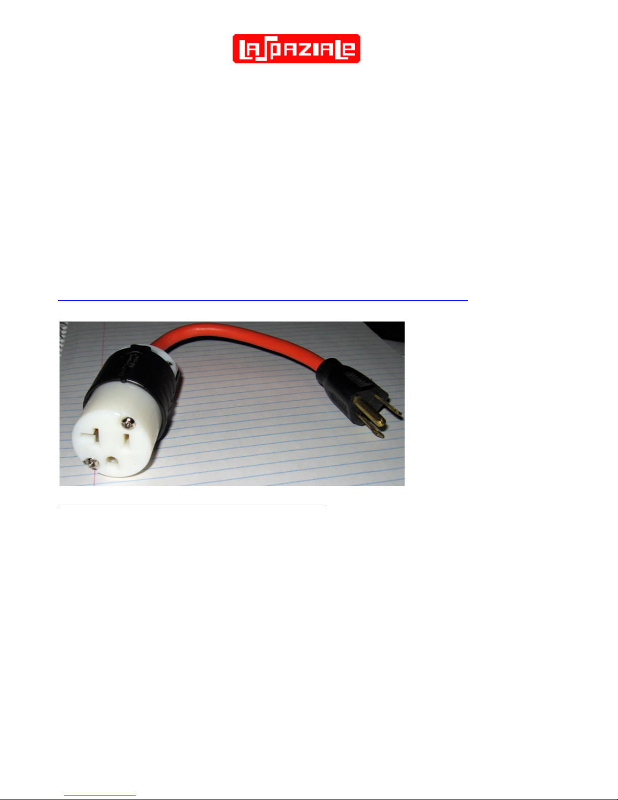
The 20A VII allows both boilers to operate simultaneously. HOWEVER, it is possible to place
the 20A VII into 15A mode without removing the covers from the machine and flipping the
internal mode switch. This is called ECONOMY mode and is described later in this manual.
As a temporary solution, Economy mode is a great option for those that really want the 20A
machine but that do not currently have a 20A circuit. However, this will require swapping out
your standard 15A outlet with a 20A outlet. These are readily available from most hardware
stores. For a more temporary solution there is an alternative such as this adapter cable
available from Chris Coffee Service:
http://www.chriscoffee.com/products/home/espressoaccs/20t015adaptorplug. It is also
available elsewhere or you can make your own with a quick trip to your local hardware store.
Locating/Changing the 15A / 20A Mode Switch
1. The Vivaldi VII must be unplugged and allowed to cool down first.
2. Remove any cups from the cup warming tray (7)
3. Remove the single screw in the front middle of the cup warming tray (7) as shown in
the photo below
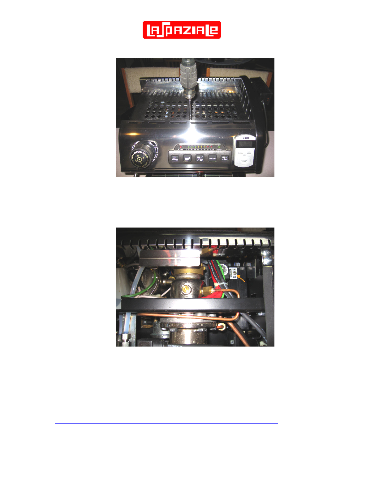
S1 Vivaldi II Owner’s Manual
Page 7
4. From the front of the machine look down into the top of the machine. In the right rear
of the machine you will see a toggle switch with its positions labeled 15 and 20. Reach
down with the same screwdriver you used to remove the cup warming tray and flip the
switch to the desired position.
4.2 Optional On/Off Timer Accessory – Overview and WARNING
The S1V2 has an optional On/Off Timer that can be purchased which provides the capability
for up to 3 On/Off cycles per day with a different program for all 7 days of the week, if so
desired. Each new machine has the cable needed to plug this timer into cable tied into place
just behind the front panel. More information including the installation manual can be found
here: http://s1cafe.com/s1v2/images/Vivaldi%20Timer%20Instructions.pdf
S1 Vivaldi II Owner’s Manual
Page 8
There is a switch labeled ON / OFF on top of the controller box adjacent to the 15A/20A
switch shown in the above photo. (The ON/OFF switch is hidden in the photo.) This switch
must be set to OFF if you do not have the Timer plugged in and it must be set to ON when
the timer is installed. Also, the state of this switch is only sensed when the power cable is
unplugged, then plugged back in. So if you need to change this switch you will need to
unplug the machine for at least 5 seconds after you do so.
WARNING: If you do NOT have the Timer installed but you have the switch set to ON, the
pump will not come on when you try to pull a shot.
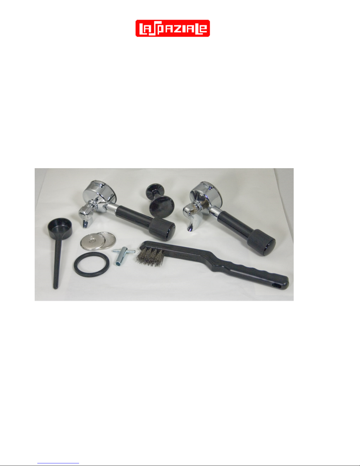
4.3 Initial Installation Before Connecting Power
After removing the VII from its packing carton and setting it on the counter, check for
additional installation instructions that may be included. You should also have all the
accessories shown in the photo below including a rubber backflush disk (not shown).
Tip the VII on its side. Twist all four rubber feet (3) hand tight as they may vibrate loose
during shipping. While performing that task, use a screwdriver to ensure that the four screws
on the bottom (two on each side between the rubber feet) which fasten the two side panels
(5) to the chassis bottom are tight. These steps will help ensure the quietest possible
operation of your VII.
Be sure you connect the included water hose to the threaded water inlet on the bottom of the
machine. Proper connection is obvious since there is only one place it can attach. The
opposite end of the hose - which connects to the water supply - may require adapters from
your local hardware store depending on your specific situation. Contact your VII dealer for
advice if the solution isn’t obvious. Also, your VII dealer may request that you check that your
water hardness is below a certain level to ensure long life and trouble free operation.

S1 Vivaldi II Owner’s Manual
Page 9
Hardness test strips may be included for this purpose. If your water fails this test, contact
your VII dealer and discuss the available options.
Once water supply is properly attached, turned on, and the desired basket has been inserted
into one of the portafilter handles, attach the portafilter to the group. Be sure that the drip tray
is installed by sliding it into place at the bottom front of the machine.
4.4 Turning On and Heating the Machine
1) Insert the plug into the 110V AC socket, the On/STBY light (22) starts flashing. (Standby mode).
2) Press the ON / OFF (27) button and keep it pressed for about 3 seconds, the green
On/STBY light (22) changes from flashing to steady indicating the machine is ON. At
the same time the lights from (14) to (21) turn on steadily for about a second
(indicating power on test mode).
3) The light corresponding to the set temperature starts flashing to indicate that the group
is heating and the automatic boiler refill starts until the water level preset by the
manufacturer is reached.
4) Once the filling process is finished, the BOILER light (13) starts flashing to indicate
that the boiler is heating. However, after first switching on, the boiler doesn't work until
the group has reached the set temperature.
5) Fasten the portafilter handle (11) to the brewing group (10).
6) Wait until the set temperature is reached, by checking that the lights on the control
panel (9) gradually turn on as the temperature rises. The visualization starts as soon
as the temperature reaches 91°C (turning on of light 14) and continues until the
machine has reached its operating temperature (light from flashing to fixed).
7) When the group has reached the set temperature, the boiler heating starts (BOILER
light (13) flashing), once it reaches the set temperature the light becomes fixed.
8) Every time the group temperature or the boiler temperature drops under the set value,
the respective light starts flashing (heating phase) until the set temperature is reached.
9) The machine is now ready.
WARNING!!
To activate and deactivate the boiler mode press the BOILER (26) button. Every time you
turn on the machine, the boiler is in service.
When the boiler is turned off, it is impossible to use hot water for infusions or steam delivery.
The machine can also operate in the economy mode (see relative paragraph).
4.5 Espresso Brewing
1. Unfasten the portafilter handle (11) from the brewing group (10) and insert the filter for
one or Double Cups. Fill it with ground coffee (aprox 7g for a single or 14-15g for a
double), making sure not to leave coffee powder on the upper edge of the portafilter
handle (11), and press it with the suitable coffee tamper provided.
2. Firmly attach the portafilter handle (11) to the brewing group (10).
 Loading...