

LTA-260
ATSC Converter Box
~
[][]IOOLBVr
DIGITAL
0DTt/
STANDARD
DEFINtTlONTElEV1SION
Product that have earned the ENERGY STAR@ are designed to
protect the environment through superior energy efficiency
ATSC Converter Box
1. Important Safety Instru ctions ------------------------------------------------ 02
2. Trad ema rks --------------------------------------------------------------------- 04
3. Accesso ries --------------------------------------------------------------------- 04
4. Before Ope rati ng --------------------------------------------------------------- 04
5. Quick Reference Control Operation ---------------------------------------- 07
5-1 . Front Panel ---------------------------------------------------------------- 07
5-2. Rea r Pa ne I ----------------------------------------------------------------- 07
5-3. Remote Control ----------------------------------------------------------- 07
5-4. Easy Setu p For Fi rst Use ------------------------------------------------ 08
5-5. Anten na Setu p ------------------------------------------------------------ 10
6. Basi c Operation ---------------------------------------------------------------- 11
6-1. Channel Scan ------------------------------------------------------------- 11
6-2. Channel Information ----------------------------------------------------- 11
6-3. Change Viewing Channel ------------------------------~---------------- 12
6-4. OS0La ng uag e ----------------------------------------------------------- 12
6-5. Closed Caption ----------------------------------------------------------- 12
6-6. Parental Control (V-CHIP) ---------------------------------------------- 13
6-7. Mute ------------------------------------------------------------------------- 18
6-8. Audio Menu ---------------------------------------------------------------- 18
6-9. Scree n Mode -------------------------------------------------------------- 19
6-1O.Sleep Timer---------------------------------------------------------------- 19
7. Before Calling For Service --------------------------------------------------- 19
7-1. Quick Service Check List ----------------------------------------------- 19
8. Gen era I Specifi cation s -------------------------------------------------------- 20
9. Remote Controller Code ------------------------------------------------------ 21
10. Li mited Warra nty ------------------------------------------------------------- 22
- 01 -
ATSC Converter Box
-
A
A
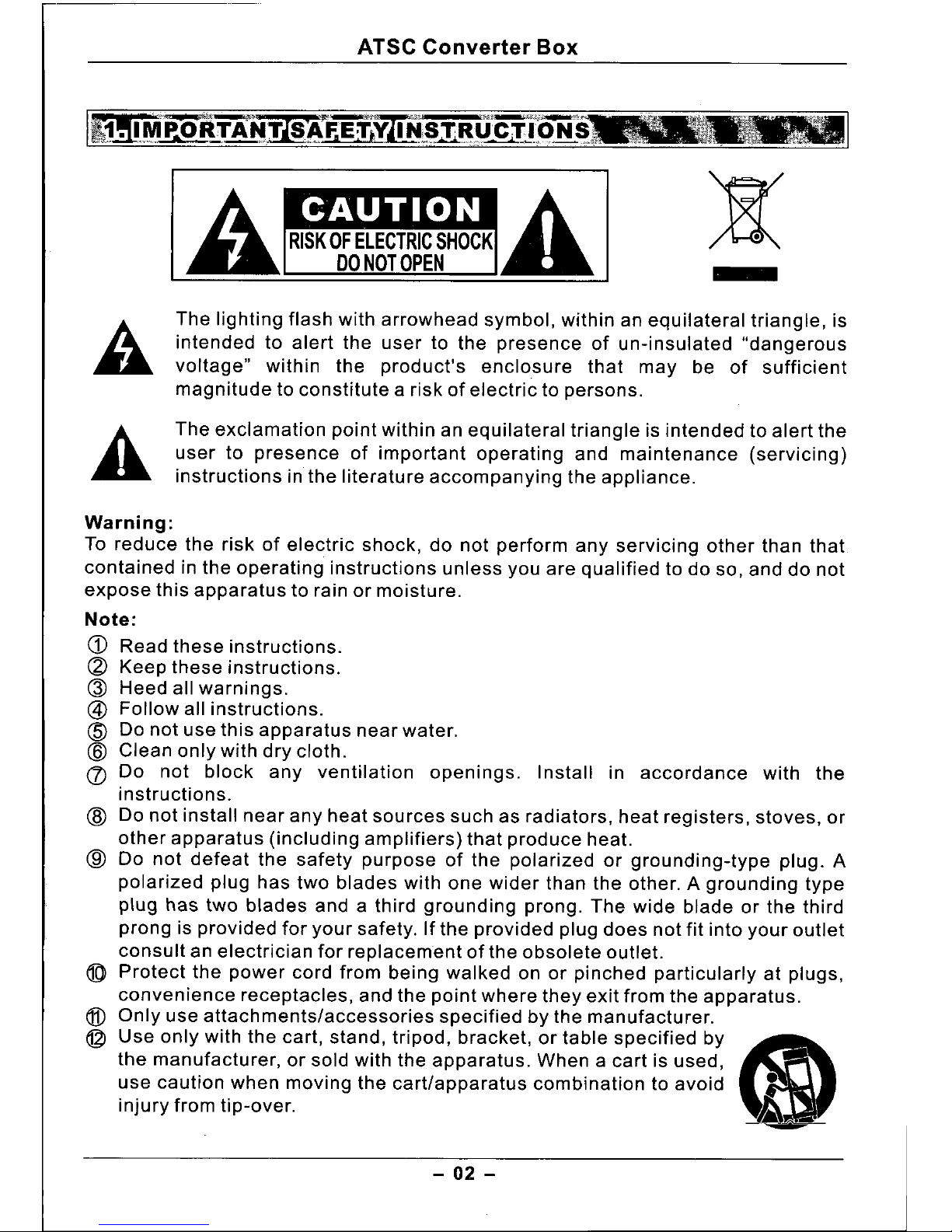
The lighting flash with arrowhead symbol, within an equilateral triangle, is
intended to alert the user to the presence of un-insulated "dangerous
voltage" within the product's enclosure that may be of sufficient
magnitude to constitute a risk of electric to persons.
The exclamation point within an equilateral triangle is intended to alert the
user to presence of important operating and maintenance (servicing)
instructions in the literature accompanying the appliance.
Warning:
To reduce the risk of electric shock, do not perform any servicing other than that
contained in the operating instructions unless you are qualified to do so, and do not
expose this apparatus to rain or moisture.
Note:
CD
Read these instructions.
~ Keep these instructions.
Q)
Heed all warnings.
@
Follow all instructions.
CID
Do not use this apparatus near water.
@
Clean only with dry cloth.
(/) Do not block any ventilation openings. Install in accordance with the
instructions.
CID
Do not install near any heat sources such as radiators, heat registers, stoves, or
other apparatus (including amplifiers) that produce heat.
@
Do not defeat the safety purpose of the polarized or grounding-type plug. A
polarized plug has two blades with one wider than the other. A grounding type
plug has two blades and a third grounding prong. The wide blade or the third
prong is provided for your safety. If the provided plug does not fit into your outlet
consult an electrician for replacement of the obsolete outlet.
@
Protect the power cord from being walked on or pinched particularly at plugs,
convenience receptacles, and the point where they exit from the apparatus.
@
Only use attachments/accessories specified by the manufacturer.
@
Use only with the cart, stand, tripod, bracket, or table specified by
<ml
the manufacturer, or sold with the apparatus. When a cart is used,
use caution when moving the cart/apparatus combination to avoid -
injury from tip-over.
1\
~
- 02 -
ATSC Converter Box
@ Unplug this apparatus during lightning storms or when unused for long periods
of time.
@
Refer all servicing to qualified service personnel. Servicing is required when the
apparatus has been damaged in any way, such as power-supply cord or plug is
damaged, liquid has been spilled or objects have fallen into the apparatus, the
apparatus has been exposed to rain or moisture, does not operate normally, or
has been dropped.
~ To Reduce the Risk of Fire or Electric Shock, Do not Expose This Appliance To
Rain or Moisture.
q9J
Apparatus shall not be exposed to dripping or splashing and no objects filled
with liquids, shall not be placed on the apparatus.
The Shock Hazard Marking and Associated Graphical Symbol is provided on the
back panel of unit.
@
Plug the adapter into AC11 OVoutlet, Connect the supplied adapter in the slot of
the unit marked "DC IN", If the unit will not used for a long time, remove the
adapter from the outlet.
Before connect the adapter and the unit, make sure that all the connections
have been made.
@)
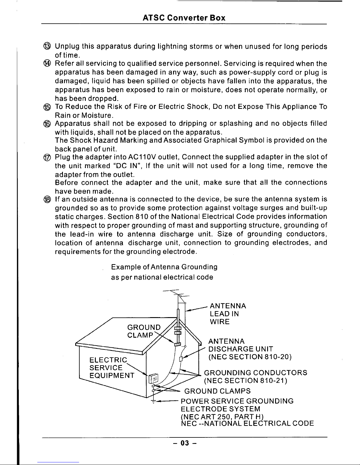
If an outside antenna is connected to the device, be sure the antenna system is
grounded so as to provide some protection against voltage surges and built-up
static charges. Section 810 of the National Electrical Code provides information
with respect to proper grounding of mast and supporting structure, grounding of
the lead-in wire to antenna discharge unit. Size of grounding conductors,
location of antenna discharge unit, connection to grounding electrodes, and
requirements for the grounding electrode.
Example of Antenna Grounding
as per national electrical code
ANTENNA
LEAD IN
WIRE
ANTENNA
DISCHARGE UNIT
(NEC SECTION 810-20)
GROUNDING CONDUCTORS
(NEC SECTION 810-21)
GROUND CLAMPS
.,.'- POWER SERVICE GROUNDING
ELECTRODE SYSTEM
(NEC ART 250, PART H)
NEC --NATIONAL ELECTRICAL CODE
- 03 -
ATSC Converter Box
[Ff,CCNotice1
This device complies with Part 15 of the FCC Rules. Operation is subject
to the following two conditions: (1) this device may not cause harmful
interference, and (2) this device must accept any interference received,
including interference that may cause undesired operation.
WARNING: FCC Regulations state that any unauthorized changes or
modifications to this device not expressly approved by the manufacturer
could void the user's authority to operate this device.
[][]IOOLBVr
DIGITAL
Manufactured under license from Dolby Laboratories.
"Dolby" and the double-D symbol are trademarks of
Dolby Laboratories. Confidential Unpublished works.
@1992-1997 Dolby Laboratories, Inc. All rights reserved.
4.
BEFOJI~QfERATING
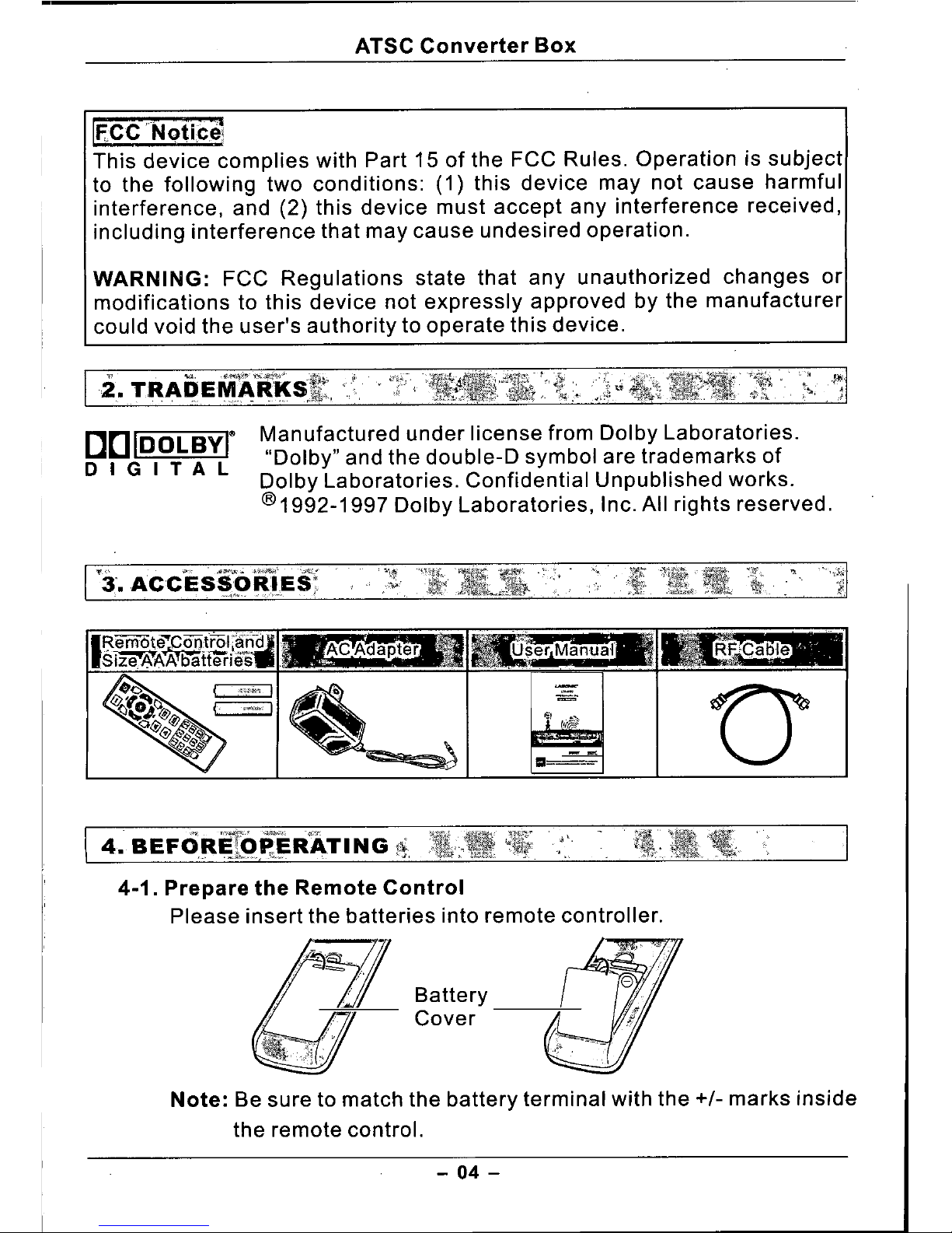
4.1. Prepare the Remote Control
Please insert the batteries into remote controller.
Battery
Cover
Note: Be sure to match the battery terminal with the
+/-
marks inside
the remote control.
- 04-
ATSC Converter Box
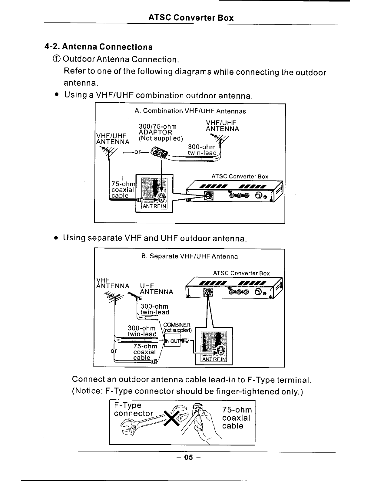
4.2. Antenna Connections
<D
Outdoor Antenna Connection.
Refer to one of the following diagrams while connecting the outdoor
antenna.
• Using a VHF/UHF combination outdoor antenna.
A. Combination VHF/UHF Antennas
300/75-ohm
ADAPTOR
(Not supplied)
VHF/UHF
ANTENNA
300-ohm
twin-lead
ATSC Converter Box
• Using separate VHF and UHF outdoor antenna.
B. Separate VHF/UHF Antenna
ATSC Converter Box
VHF
ANTENNA
300-ohm
twin-lead
-
\
COMBINER
30.0-ohm (notsupplied)
tWin-lead
Cl-
-~
75-0hmj
coaxial
cablellt}
Connect an outdoor antenna cable lead-in to F-Type terminal.
(Notice: F-Type connector should be finger-tightened only.)
F-Type ~
l~
!/i--:
75-ohm
co~~~ - coaxial
~ ~ cable
- 05 -
ATSC Converter Box
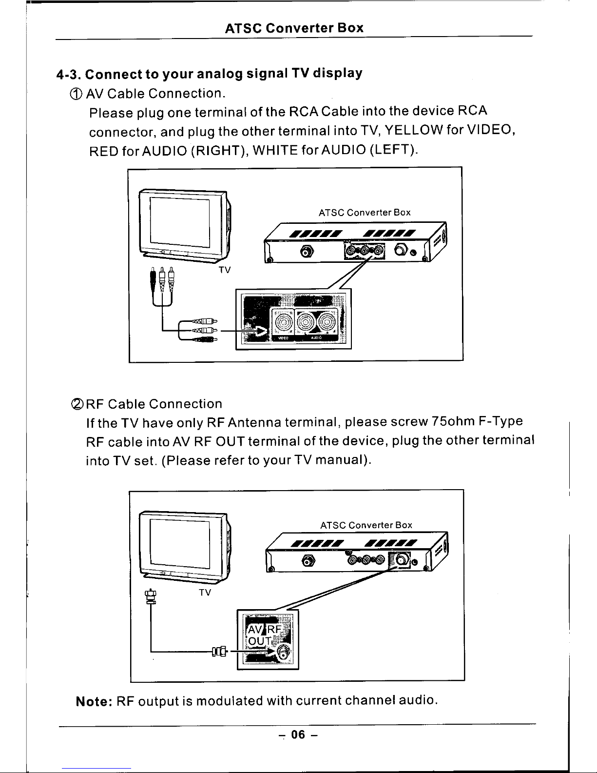
4.3.
Connect to your analog signal TV display
CD
AV Cable Connection.
Please plug one terminal of the RCA Cable into the device RCA
connector, and plug the other terminal into TV, YELLOW for VIDEO,
RED for AUDIO (RIGHT), WHITE for AUDIO (LEFT).
o
~TV
ATSC Converter Box
(2)
RF Cable Connection
If the TV have only RF Antenna terminal, please screw 750hm F-Type
RF cable into AV RF OUT terminal of the device, plug the other terminal
into TV set. (Please refer to your TV manual).
o
L
ATSC Converter Box
Note: RF output is modulated with current channel audio.
- 06 -

ATSC Converter Box
~~~~~~~~:~~Jlo.l~ratJ~
5.1.
Front Panel
CD
Power Button:
Press - On;
Press Again - Standby.
5-2. Rear Panel
(2)
Power Indicator:
On means work normally,
Off means no power or standby.
(3)
IR window:
Infrared receiving window.
CD
ANT RF IN: Antenna RF Input.
(2)
Video: Video Output.
(3)
Audio L : Audio Left Output.
@
Audio R : Audio Right Output.
@
AV RF OUT: AudiolVideo RF
Output.
(6)
&Co-<tl:ACAdapterDC IN(+5V).
5-3. Remote Control
CD
MUTE: Mute or restore sound.
(2)
SCREEN: Select TV Mode: 4:3 or 16:9.
(3) .•••/~ :
Decrease/Increase audio volume.
or move cursor in menu screen.
@
INFO: Display viewing channel information.
(5)
ANT LEVEL: Display Antenna RF signal
strength and quality.
<ID
CH SCAN: Start channel auto scanning.
(/) 0-9: Set the channels or number keys.
(8)
AUDIO: Select audio language.
@
<b
POWER: Power ON/ OFF.
Remote
Control
- 07 -

ATSC Converter Box
@ SLEEP: Switch the sleep timer setting.
Qj)
OK: Use to confirm the channel selection and other operation.
@ C/C: Switch Close Caption Service or On/Off.
o
CH+/CH-: Select next / previous channel or move the highlight for
menu item.
9
V-CHIP MENU: Enter or exit the V-CHIP setting menu.
@
V-CHIP ON/OFF: V-CHIP on / off temporarily.
@ LANGUAGE: Select OSD language: English / Spanish / French.
5-4. Easy Setup for first use
Please check and follow below instructions to enjoy the digital TV program.
(j)
Insert the batteries into remote control.
(2) Connect the antenna cable into the device.
(3) Connect the audio/video or RF output into your TV.
@ Connect the AC adapter to DC IN Jack of the device, and then plug the
AC adapter to the outlet.
(5) Press POWER to turn on the device, the Power LED will be lighten.
(6) Turn on your TV, and refer to the TV manual.
• If you use RCA cable, please switch toAV IN .
• If you use RF cable, please rescan the TV channels.
ATSC Converter Box
drUP
~
ANT RF IN
DC IN
0
_AVRFOUT
TV
- .08 -

ATSC Converter Box
(J)
Press
lOCHSCAN"
to scan ATSC program channels.
T
"
sc
1
Press "OK" to start Auto scan, It may take you several minutes.
Note:
• If you use F-Cable to connect the equipment and the TV, please set
"Audio Mode" to 'Mono" mode.
If you change the RF Channel to CH3 or CH4, you need to rescan.
(Please refer to your TV manual.)
• While you use RCA cable to connect to your TV. If your TV only have
one jack for audio in, you can set "Audio Mode" to "Mono" mode.
Unless set "Audio Mode" to "Stereo" mode .
• To Select the Time zone, use "CH+/CH-" to focus "Time Zone",
then use"
<Ill / ~
"to select the zone where you are located: Alaska,
Haweii, Pacific, Mountain, Central, Eastern.
- 09 -

ATSC Converter Box
@
Press "LANGUAGE" to select OSD language: English, French,
Spanish.
5-5. Antenna Setup
CD
Press "ANT LEVEL" to display Antenna Level.
(2)
Press "CH+/CH." to select the channel. It will show the current channel
signal strength and quality.
(3)
Adjust the antenna direction and position to receive the signal strength
level 60 or higher.
@
Press "ANT LEVEL" again to exit the antenna signal level information.
Note: Before operating the other functions, you have to exit the ANT
LEVEL.
- 10 -

ATSC Converter Box
6-1. Channel Scan
Press "CH SCAN" to scan the ATSC program channel, it will memory all
channels found.
rJB
sc\
1
• Press .•••~ to select "Auto Scan", then press "OK" to beginAuto scan.
6-2.
Channel Information
Press "INFO"to display the program information, including:
CD
Channel number, @)Resolution, @V-CHIP rating, ,
(g)
Broadcast station, @Display Format,
@
Current Time,
G)
Hour of Current Program,
(j)
Closed Caption,
@
Program information.
@Audio service type, ":.
- 11 -

ATSC Converter Box
6-3. Select Program Channel
(j)
Press "CH+/CH-" to select the channel.
CH+
~
\1
Note: It is only valid after scanning channels. (Please refer to "CH SCAN").
(2)
Press "0-9" buttons to select the channel.
[j]w[TI
wwl]]
[I] lIIcSIJ
cB\
=\
Note: 3 digit numbers need to select the channel: ~..
e
Example: Input "3" "0" "2" to select channel 30-2.
6-4.
eso
Language
Press "LANGUAGE" to select the On Screen Display Language:
English, French, Spanish.
6-5. Closed Caption
G)
The device supports Closed Caption decoding function, the "Closed
Caption" is a system which allows conversations, narration, and sound
effects in TV programs and home videos to appear as captions on the
screen.
- 12 -

ATSC Converter Box
(2) Not all the programs and videos offer closed captioning.
a>
Press
"C/C"
to get the "Closed Caption" service:
OFF ••• Service 1••.• Service2 ••.• Service3 ••.• Service4..... ServiceS
•••• Service6 ••.• Caption 1 ••.• Caption 2 ••• Caption 3-+ Caption 4
••.• Text 1 ••.• Text 2 ••.• Text 3 ••• Text 4 ••.• OFF.
6-6. Parental Control (V-CHIP)
CD
This function allows you to restrict TV programs based on FCC data,
and prevent your children from watching violence or sexual scenes
that maybe harmful.
(2) Restriction of TV programs includes two characters that contain
information about MPAA rating and the TV Parental Guidelines. MPAA
is restricted by age. TV Parental Guidelines are restricted by ages
and contents.
• MPAA RATING
Rating
G
General Audiences
All ages admitted.
Parental
PG
Guidance
Some material may not be
Suggested
suitable for children.
Parent Strongly
Some material may be
Age
PG-13
Cautioned
inappropriate for children
Based
under 13.
Under 17 requires
R
Restricted
accompanying parent or adult
guardian.
NC-17
No 17 and under Admitted.
X
Unified with NC-17.
NR
Not Rated
- 13 -

ATSC Converter Box
• TV PARENTAL GUIDELINES.
Rating
TV-Y
All children.
TV-Y? Direct to Older Children.
Age
TV-G
General Audience.
Based
TV-PG
Parental Guidance Suggested.
TV-14
Parents Strongly Cautioned.
TV-MA
Mature Audience Only.
ALL
All Scenes blocked.
FV
Fantasy Violence Scene.
Content
V
Violence Scene.
Based
S
Sexual Situation.
L
Adult Language.
D
Sexually Suggestive Dialog.
- 14 -

ATSC Converter Box
~ Selecting a lower age rating's content setting to block automatically
change the same higher age rating's content setting to block.
@ How to set V-CHIP.
• Press "V.CHIP MENU" to access V-CHIP menu screen, and then set
up V-CHIP.
Need to input password by press "0-9" (default is "0000") .
• Press "CH+/CH." to select the "TV PG" and "MPAA".
Press "OK" to access the parental control screen.
Press "V-CHIP MENU" to exit the V-CHIP Menu Screen.
• Press "CH+/CH-" to select the rating and press "OK" to block
the rating, higher rating will be blocked automatically.
Press "V-CHIP MENU" to main V-CHIP menu.
- 15 -

ATSC Converter Box
CH_
I~~~-1
rl1lJ~_
---~--"-_. -~-------_._-_._---F
, 0
lI\W@
IgO
W#i?
~
~
~
,~
~
IL
I~
~~
..
II II
- 16 -
----

ATSC Converter Box
• While program exceeds the rating setting, screen will show
"V-CHIP block" , and video /audio will be blocked.
1). Press "V-CHIP ON/OFF" to inactive the V-CHIP temporarily.
The correct password is needed for it.
2). If you turn the power on from off, the "V-CHIP block" will be
activated again.
C5
Downloadable Digital Rating .
• When the system receives Downloadable Digital Rating Table, the
"Downloadable RRT" item will be actived in V-CHIP Menu Screen .
• Use "CH+/CH-" to Select "Downloadble RRT" and press "OK", it will
show the all Dimensions of digital rating
-17-

ATSC Converter Box
• Use "CH+/CH-" to select the Dimension and press "OK" to show
all rating setting of the chosen Dimension .
• Use "CH+/CH." to choose V-CHIP rating, and press "OK" to block or
unblock the specific rating program.
• Press "V-CHIP MENU" to exit current menu screen.
6-7.
MUTE
• Press "MUTE" to mute all audio out,
• Press "MUTE" again to cancel mute.
r_1
I.'~~I
6-8.
AUDIO MENU
Press "AUDIO" to select the Audio Language: English, Spanish,
French.
- 18 -

ATSC Converter Box
screen: 16:9screen: 4:3 PSscreen: 4:3 LBSource
6-9. SCREEN MODE
Press "SCREEN" to select screen mode: 4:3LB, 4:3PS, 16:9.
6-10. SLEEP TIMER
Press "SLEEP" to display current Sleep Timer
Press "SLEEP" again to change the sleep timer setting:
• 240Min -+ OFF -+ 30Min -+ 60Min -+ 90Min -+ 120Min -+
150Min -+180Min -+210Min.
While the timer is reached, the device will enter standby mode
automatically.
f)
.'lBef~r.~
i~~lIin'9
i~r~lr\vO:t!~
7-1. Quick Service Check List
Check these items and see if you can correct the trouble.
CD
No Picture .
• Please turn your TV on and set it right. You may refer to the TV Set
manual.
1). Check AV Cable or RF Cable is stable.
2). Check TV is set to AV IN, and AV cable is connected to
right terminal. And check the TV channel is right. If not, plese
scan the TV channels .
• Try a new channel, maybe that is station problem.
1). Rescan ATSC program.
Check antenna connection is perfect.
2). Refer to "ANT Level".
- 19 -

ATSC Converter Box
(2)
No Sound.
• Please check the AV cable is connected correctly.
• Try a new channel.
1). Maybe there is no sound for viewing program channels .
• Press "MUTE". Maybe MUTE was set before.
• Please check if your TV is on "MUTE" mode.
(3)
Remote control does not work.
• Check the batteries are installed properly.
@
The warning message about the digital broadcast.
• "No Signal".
Check the RF cable and antenna setup.
Model
LTA-260
Description
ATSC Coupon-Eligible Converter Box
RF IN
F-Type Jack for ATSC Antenna.
IN/OUT
Video
RCA Jack for Video output.
JACK
Audio
2 RCA Jack for Stereo Audio output.
RFOUT
F-type Jack for Modulated AV RF Out (NTSC CH3/4).
DCIN 5V 1.4A.
Band Width: 6MHz.
Band: 54MHz-807MHz
ATSC Compatible
CH2-69.
Modulated Method: 8VSB.
RF Sensitivity: -83 - -5dBm.
Audio Spec
Level: 1.2Vrms (1kHz).
SIN: >60dB.
Video Spec
Level: 1Vpp.
Operating Temperature
5' C - 35' C
Size
180(L) X 124(W) X 27(H)mm.
Weight
850g
- 20-

ATSC Converter Box
9-1. Identify custom code: OOFF.
9-2. Remote key code.
811
DAa
(.)
DtafCJ
INFO
CH. CIC
~ V.CHIP
~ MENU
~.
@7 __ ~
ee)
~--~
~~
~~
~~~
@Q]~@]J
[i9@]][E]
[TI]@]][9
~
~
V.CHIP
ON/OFF
9-3. Universal Remote Controller setting
For using Universal Remote Controller, please set the remote code as
TOSHIBA TV or DVD. More information, please refer to the user
manual of Universal Remote Controller.
After setting up successfully, "POWER", "CH+", "CH-", "VOL+", "VOL-"
can be functioned by the Universal Remote Controller.
Note: You may need to try every TOSHIBA code to find the properly remote
controller code.
- 21 -

ATSC Converter Box
II1~i~~liiih:~PJY
Consumer limited Warranty
LASONIC warrants to the first consumer purchaser that this product, when
shipped in its original container, will bEifree from defective workmanship and
materials, and agrees that it will, at its option, either repair the defect or replace
the defective Product or part thereof with a new or remanufactured equivalent at
no charge to the purchaser for parts or labor for the period(s) set forth below.
This warranty does not apply to any appearance items of the Product nor to the
additional excluded item(s) set forth below nor to any Product the exterior of
which has been damaged or defaced, which has been subjected to improper
voltage or other misuse, abnormal service or handling, or which has been altered
or modified in design or construction.
In order to enforce the rights under this limited warranty, the purchaser should
follow the steps set forth below and provide proof of purchase to the service.
The limited warranty described herein is in addition to whatever implied
warranties may be granted to purchasers by law. ALL IMPLIED WARRANTIES
INCLUDING THE WARRANTIES OF MERCHANTABILITY AND FITNESS FOR
USE ARE LIMITED TO THE PERIOD(S) FROM THE DATE OF PURCHASE SET
FORTH BELOW. Some states do not allow limitations on how long an implied
warranty lasts, so the above limitation may not apply to you.
Neither the sales personnel of the seller nor any other person is authorized to
make any warranties other than those described herein, or to extend the duration
of any warranties beyond the time period described herein on behalf of LASONIC .
The warranties described herein shall be the sole and exclusive warranties
granted by LASONIC and shall be the sole and exclusive remedy available to the
purchaser. Correction of defects, in the manner and for the period of time
described herein, shall constitute complete fulfillment of all liabilities and
responsibilities of LASONIC to the purchaser with respect to the Product, and
shall constitute full satisfaction of all claims, whether based on contract,
negligence, strict liability or otherwise. In no event shall LASONIC be liable or in
any way responsible, for any damages or defects in the Product which were
caused by repairs or attempted repairs performed by anyone other than an
authorized servicer. Nor shall LASONIC be liable or in any way responsible for
any incidental or consequential economic or property damage. Some states do
not allow the exclusion of incidental or consequential damages, so that above
exclusion may not apply to you.
THIS WARRANTY GIVES YOU SPECIFIC LEGAL RIGHTS. YOU MAY ALSO
HAVE OTHER RIGHTS WHICH VARY FROM STATETO STATE.
- 22-

 Loading...