

Page 1
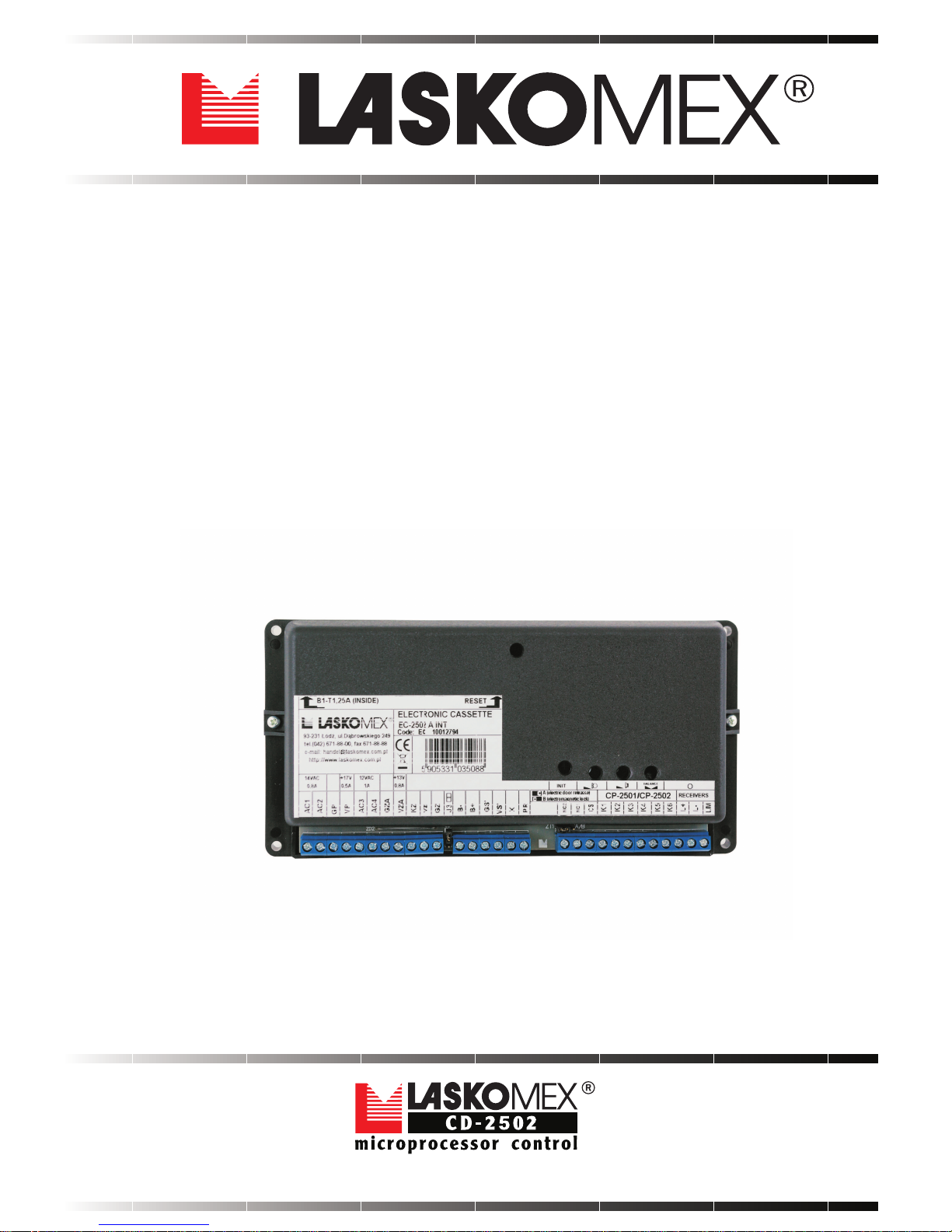
DIGITAL ENTRY PHONE SYSTEM
INSTALLATION, SERVICE
AND PROGRAMMING MANUAL
OF ELECTRONIC CASSETTE
EC-2502
Page 2
Page 2
EC-2502
LASKOMEX PPUH, ul. D¹browskiego 249, 93-231 £ód, tel. (42) 671 88 00, fax (42) 671 88 88, e-mail: [email protected], http://www.laskomex.com.pl
CONTENTS
1. Safety and usage conditions 3
2. Installation of electronic cassette and power supply adaptor 3
3. Configuration 3
4. Adjustment 4
5. Programming of entry phone 5
6. Restore the initial settings 7
7. Conformity with previous versions 8
8. Faults messages 8
9. Technical data 8
10. Descriptions of terminals 9
11. Dimensions of elements 9
12. Selection of wires and connection diagrams 10
Changes in software (electronic cassette):
- Added function that turns off the camera in an external panel during
the call - an additional option "b" in the calling options in individual
settings.
- Changed name of parameter EUC on CAon
- Added parameter CAin that determines the supported video inputs
of CVP-x switch
- Added parameter CAtP that determines time interval of switching
picture
- Added the ability to cooperate with the CVP-2 switch
- Removed P-7 procedure (electro-catch test)
- Moved MLX support to P-7 - exchange of data requires an administrator
password
- Added function of testing the electro-catch control frequency after
changing the Fry parameter
- Increased entrance preview time after the entry of coded lock code
- Added keypad blocking function during RFID reading
- New parameters LdP and NbP in H version of electronic cassette in
procedure P-1
- New parameter APo in procedure P-2
- Removed parameters t1t, F1 and F2 from procedure P-1
- Additional numbers are priority numbers
- If local number is in the range of serviced numbers and is turn off,
than is automatically treated as unserviced number - important for
LdP
- Added function that turns off confirmation the use of coded lock and
electronic keys for individual occupant - additional option "P" in Calling
option (parameter No. 4 in procedure P-5)
- Added parameter CHA in procedure P-2.
- Changed name of parameter Ldn on Un in procedure P-1.
- Changed names of parameters ibE and ibA on idE and idA in procedure
P-2.
- Increased speed of searching electronic keys
- Added 10 additional numbers out of serviced range
- Added DJ function
- Improve P-4-0 function in H version of electronic cassette
- Added automatic door open function - additional option "d" in Entrance
service (parameter No. 5 in procedure P-5)
Software
version
Version
release date
Changes
v6_8
v6_6
v6_7
11-2010
06-2010
01-2010
Page 3
Page 3
EC-2502
LASKOMEX PPUH, ul. D¹browskiego 249, 93-231 £ód, tel. (42) 671 88 00, fax (42) 671 88 88, e-mail: [email protected], http://www.laskomex.com.pl
coil
1. SAFETY AND USAGE CONDITIONS
Prior to the installation please read the following instruction.
Electric installation should be done in accordance with PN-IEC-60364-1 norm by the authorized
person. Installation should not be directly exposed to atmospheric electrostatic discharge.
It is forbidden to connect the panel to other installations, with exception of the application
recommended by the producer.
Electronic cassette should not be exposed to high temperature or humidity.
Self maintenance is only permitted for qualified persons. Device maintenance by unauthorized
persons may result in the lost of warranty.
It is forbidden to connect power supply from sources with different parameters than recommended
by the producer to panel clamps. The producer is not responsible for any lost occurred due the
usage of improper power supplies.
Signals from the digital entry phone system should not be directly connected to RTV sets,
because of risk of devices and system damages.
Do not clean the electronic cassette with gasoline, solvents or strong detergents as it may cause
damage of the device surface.
2. INSTALLATION OF ELECTRONIC CASSETTE AND POWER SUPPLY ADAPTOR
Electronic cassette and power supply adaptor should be mounted inside the building, most preferably
in a place which is not accessible for unauthorized persons. It is recommended to place both devices
in an installation box. The cassette is mounted by means of 4 screws. To the place where the power
supply adapter is mounted supply from power network should be routed.
Electronic cassette casing is fixed to the base by means of two screws.
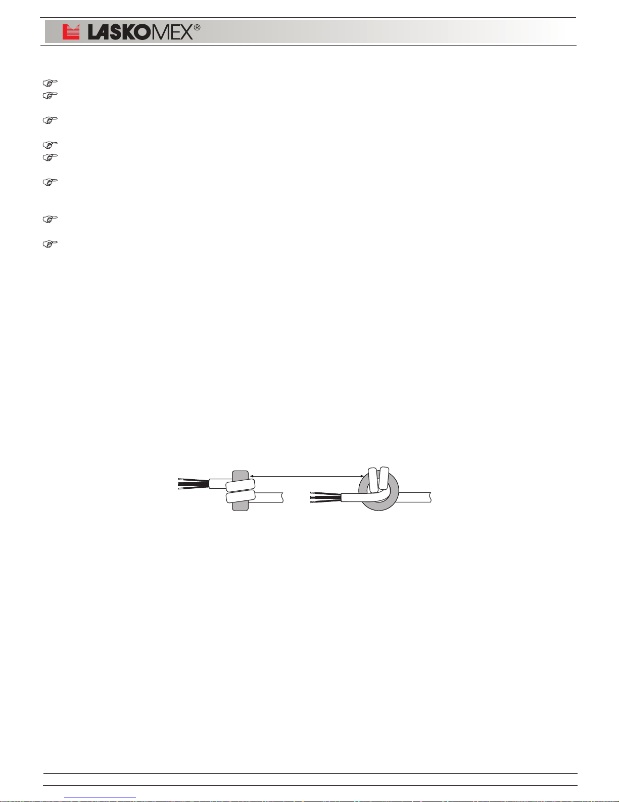
Wire ends from feeding transformer should be wound on the smaller ferrite core included in the set.
Each wire should be wound 2.5 coils as shown on figure 1. Wire connecting the talking cassette
with electronic cassette should be wound similarly - at the side of electronic cassette the wire end
should be wound on the bigger core. If this is impossible due to the thickness of wire, insulation
should be removed and only those wires which are used for connection should be wound on the
core. Connect the wires according to connection diagram.
Figure 1: Assembly of ferrite core on wires
3. CONFIGURATION
NOTE!
In the description abbreviations are used - exchange configured for the service of the main entrance
is designated EC-2502/H and exchange for the service of subordinate entrance EC-2502/U.
In entry phone CD-2502 one type of electronic cassette is used - EC-2502. Cassettes are default
configured as EC-2502/U. The use of the device (main or subordinate entrance) is defined by
program.
Support for the main entrance (work in H mode) requires change in cassette configuration parameter
[EtYP] (see programming, page 5). Next pushbutton INIT should be pressed and while still holding
it, pushbutton RESET should be pressed for a while and released. After approx. 2 seconds pushbutton
INIT can be released. Before initialization serial number will be displayed and after that parameters
initialization process will begin - at that time on the display of the external panel quickly changing
digits will appear. When the countdown visible on the display stops, all default settings will be
restored in the cassette and operation mode will be changed.
Page 4
Page 4
EC-2502
LASKOMEX PPUH, ul. D¹browskiego 249, 93-231 £ód, tel. (42) 671 88 00, fax (42) 671 88 88, e-mail: [email protected], http://www.laskomex.com.pl
Kaseta elektroniki
DATA:
EC-2502
ul. Nowa 20, 90-031 ód,
tel. (0-42) 672 44 00, fax 672 44 45,
e-mail: [email protected],
http://www.laskomex.com.pl
AC1
AC2GPVP
AC3
AC4
GZA
VZAKZVZGZJ3-B+B
GS
VS
14 V AC
0.8 A
+7V
0.5A
12 V AC
1 A
+13V
0.8A
+12V
L-
L+K6K5K4K3K2K1
PR/CS
BALANSMIKROFON GONIKRESET
CP-2500
A/B
P2
BALANCEMICROPHONE
LOUDSPEAKER
P1 P3
- +
- +
- +
demagnetizing off
X
SW1
SW2
a)
b)
P2P1P3
J3 ZT1
ZT1
J3
B) Electromagnetic lock
A) Electro-catch
ZT1
ZT1
J3
demagnetizing on
J3
FUSE
Socket to connect ISD-02 interface
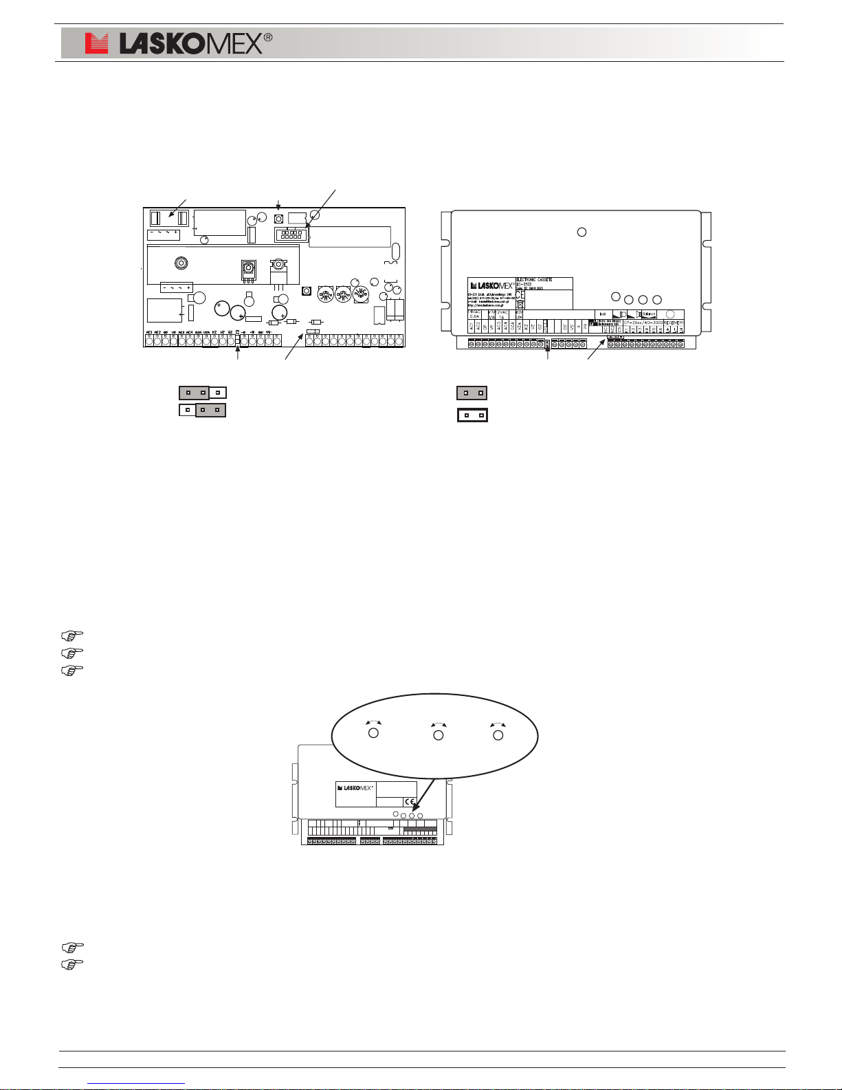
Electronic cassette EC-2502 can control electro-catch (by default setting). It is also a possibility to
control electromagnetic lock (or reverse
electro-catch). The selection of control method enables jumper ZT1.If electromagnetic lock is used
jumper should be put on joint J3 and operation frequency (parameter FrY) should be set on 0! (see
figure 2).In case electro-catch is used jumper should be removed from joint J3.
Figure 2: Selection of electro-catch or electromagnetic lock.
4. ADJUSTMENT
Elements of entry phone system are preliminarily adjusted and position of internal
potentiometers should not be changed without necessity.
Electronic cassette EC-2502 has the following adjustment elements (see dwg. 3):
P1 - volume control in external panel loudspeaker
P2 - volume control in uniphone loudspeaker (amplification of panel microphone)
P3 - line balance responsible for the lack of acoustic interference
Figure 3: Control elements in electronic cassette
Additional there are potentiometers for control acoustic track:
P4 - amplification of microphone track in external panel (potentiometer in external panel)
P1 - amplification of microphone track in uniphone (potentiometer is in uniphone)
A detailed description of the regulation of electronic cassette EC-2502 is in the installation, service
and programming instruction of digital entry phone system CD-2502.
Page 5
Page 5
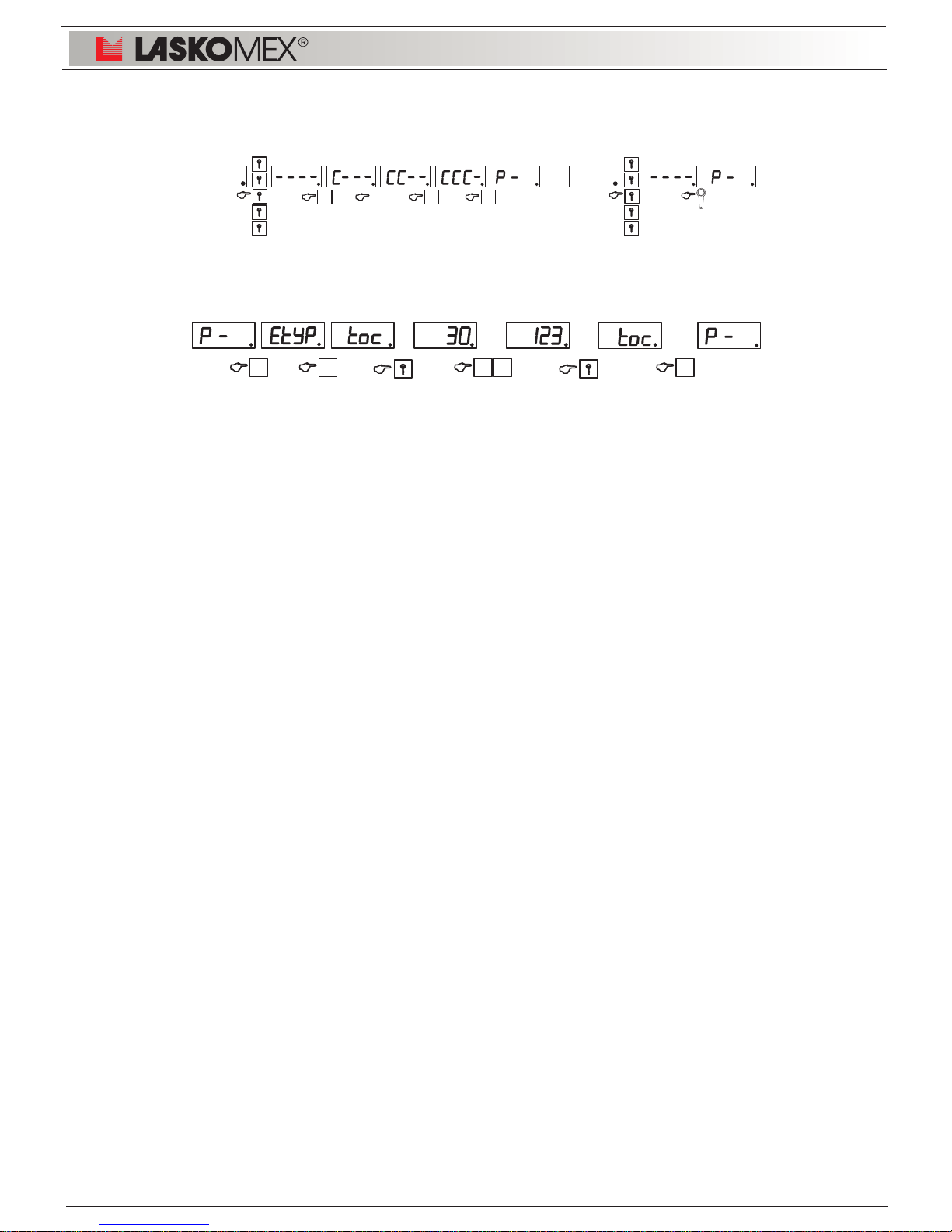
Entering programming mode
EtyP
tOc
tro
t1d
tPA
trY
FrY
CAin
CAtP
nbL
Pnu
LPi
LLo
LHi
LdP
NbP
Un
(0,1)
10...255
10...255
10...255
20...255
1...31
0...200
0...1234
1...10
0...9998
0...9998
0...100
1...240
1...240
0...9998
0...9998
0...9998
0
30
120
100
150
5
50
0
3
0
0
0
1
240
0
0
0
U,H
U,H
U,H
U,H
U,H
U,H
U,H
U
U
U
U
U
U
U
U,H
H
U
Operation mode of el. cassette; 0 - subordinate (U), 1 - main(H)
Waiting time for picking up the receiver in seconds
Time of conversation
Time of signal generation
Pause time
Time of electro-catch operation in seconds
Frequency of electro-catch supply voltage in Hz
Video inputs of CVP-x switch serviced by the CD system
Time interval of switching video signal in seconds
Block number
Range shift
Amount of rooms on the floor
Range of serviced numbers - low value
Range of serviced numbers - high value
Redirecting of not serviced numbers
Block number for redirecting of not serviced numbers
Additional number not included in the serviced range
P-2 Functions realized by entry phone
EAu
ton
dJ
APo
CEn
CEd
CPo
CEr
CHA
idE
idA
CAon
3C
Ent
NbL
1
1
0
0
1
1
1
0
0
1
1
0
0
1
1
U,H
U,H
U,H
U,H
U,H
U
U
U
U
U,H
U,H
U,H
U,H
U
H
Sound signal of sign selected from the keyboard
Multitone signaling of sign selected from the keyboard
Duration of acoustic signal of sign selected from the keyboard is
as long as time of keystroke but no longer then 1 second
Acoustic confirming opening the electro-catch
Service of coded lock
Permission to edition of coded lock codes by occupants
Permission to confirm the use of coded lock
Permission to confirm the use of a wrong coded lock
Request to enter coded lock code during entering user`s menu
Service of electronic keys
Permission to registration of electronic keys by occupants
Continuously supply of camera and illumination
Service of three-position display
Fast entrance
Mode with building numbering
0 - off; 1 - on
P-1 Operation parameters of entry phone
ENTER 5x KEY AND ENTER SUCCESSIVELY 4 DIGITS OF CODE
1 2 3 4
OR
EC-2502
LASKOMEX PPUH, ul. D¹browskiego 249, 93-231 £ód, tel. (42) 671 88 00, fax (42) 671 88 88, e-mail: [email protected], http://www.laskomex.com.pl
PARAM.
No 1
EDITION OLD VALUE
1 3
PARAM.
No 2
1 2
EDITION NEW VALUE
RETURN
C
CHANGE
ACCEPTATION
5. PROGRAMMING OF ENTRY PHONE
Page 6
Page 6
P-3-0
P-3-1
P-3-2
P-3-3
P-3-4
P-3-5
P-3-6
P-3-7
P-3-8
P-3-9
ON/OFF
FLO
FHi
LOC/OFF
L-F
F-L
SYS
CoL
OPL
Switching on/off of installation procedure
Low range of searched numbers
High range of searched numbers
Searching for the picked up (incorrectly placed) receiver
Blocking the possibility of using an entry phone
Calculator converting uniphone logical number to its physical
Calculator converting the physical number to logical
Restoring the default parameters of the central unit operation
(defined by procedures P-1 and P-2).
Restoring the default values of the coded lock
Restoring the default values of individual settings
P-4 Electronic keys
P-4-0
P-4-1
P-4-2
P-4-3
P-4-4
P-4-5
P-4-6
P-4-7
P-4-9
C0
Add
AdL
AdP
deL
Ldel
Pdel
Id
SEr
Erasing electronic keys memory
Addition of key without assigned to the apartment
Addition of key with assigned to the apartment
Addition of key on the selected item in memory
Deleting the key
Deleting the key assigned to the apartment
Deleting the key recorded in the defined item
Identification of key
Addition of service key (administrator)
U,H
U,H
U
U,H
U,H
U
U,H
U,H
U,H
P-5 Individual setting
Parameter No. 1 --- Calling tone, key [1]
Parameter No. 2 --- Calling volume, key [2]
Parameter No. 3 --- Number of bells, key [3]
Parameter No. 4 --- Calling options, key [4]
Parameter No. 5 --- Entrance service, key [5]
Parameter No. 6 --- Options of coded lock, key [6]
P-6 Change of fitter coded lock
P-7 MLX module support - backup/upload of EC parameters
P-8 Release of electro-catch in service mode
P-9 Change of coded lock code
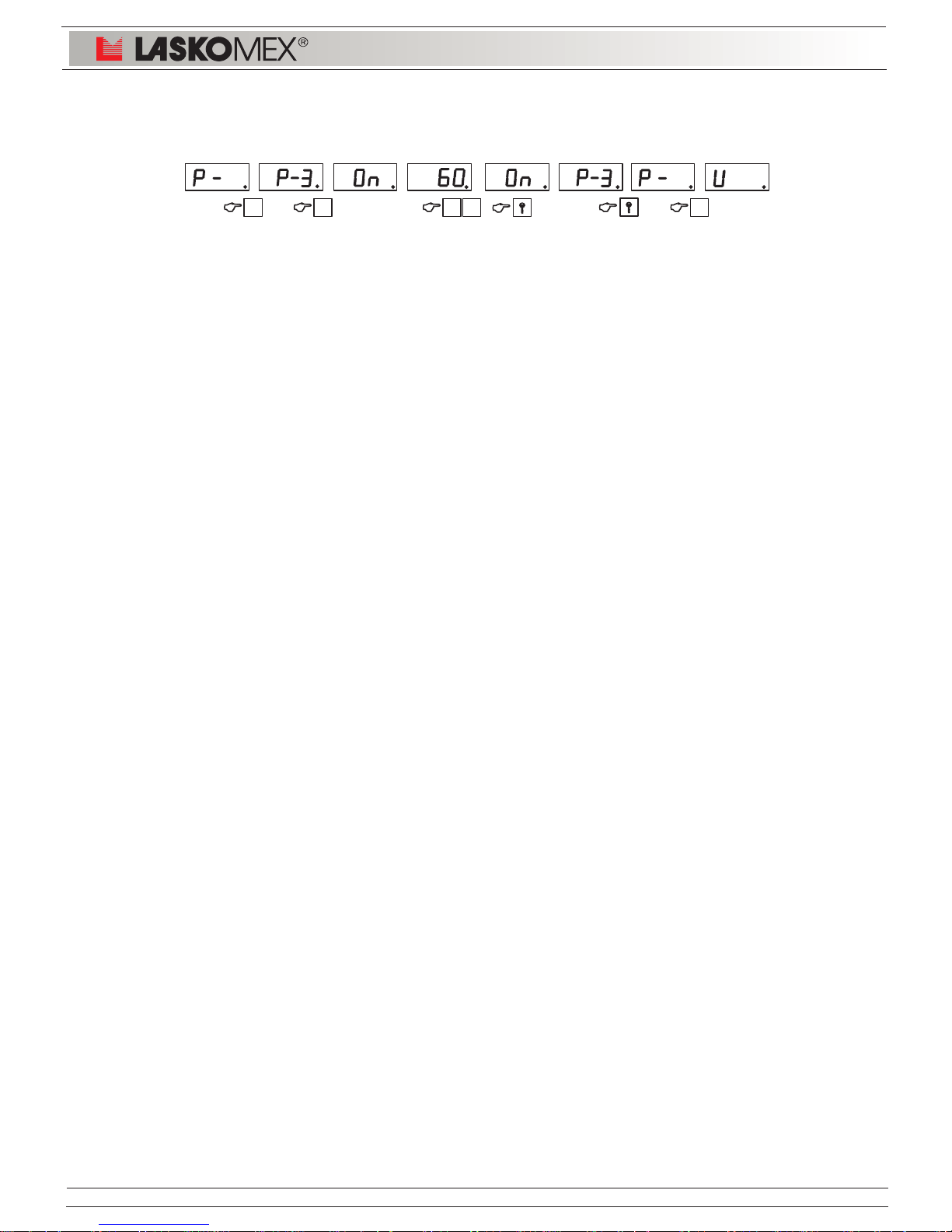
P-3 Installation procedure
EC-2502
LASKOMEX PPUH, ul. D¹browskiego 249, 93-231 £ód, tel. (42) 671 88 00, fax (42) 671 88 88, e-mail: [email protected], http://www.laskomex.com.pl
SWITCH ON THE INSTALLATION PROCEDURE
3 0 C1 2
Page 7
Page 7
EC-2502
LASKOMEX PPUH, ul. D¹browskiego 249, 93-231 £ód, tel. (42) 671 88 00, fax (42) 671 88 88, e-mail: [email protected], http://www.laskomex.com.pl
X
SW1
SW2
P2P1P3
RESET
INIT
6. RESTORE THE INITIAL SETTINGS
NOTE!
Restoring the default settings results in the loss of information stored in EEPROM memory of
electronic cassette (changed codes of coded lock, numbers of electronic keys, individual settings
etc.). Prior to this operation one should get acquainted with the content of this chapter.
Restoring the default operation parameters for electronic cassette can be done in two ways: globally
(refers to parameters set by procedures P-1, P-2, P-5, P-6 and P-10) or selectively (default values
defined by individual procedures are restored).
Global restoration of default parameters. Reset of electronic cassette.
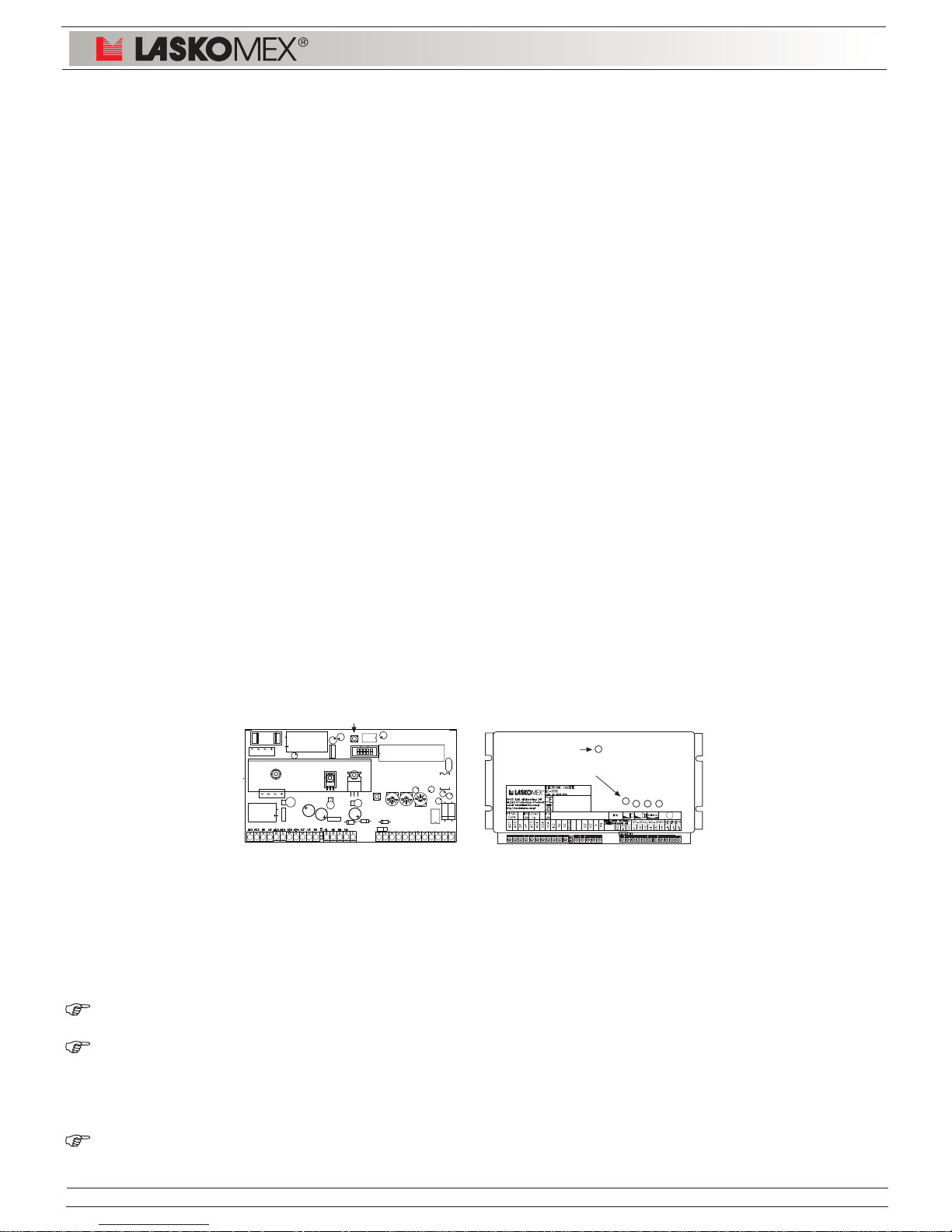
In order to restore default parameters of electronic cassette operation pushbutton INIT (SW2) should
be pressed and while still pressing it pushbutton RESET (SW1, see dwg. 2) should be pressed for
a while and released. After approx. 2 seconds pushbutton INIT (SW2) can be released, at that time
on the display of the external panel quickly changing digits will appear.
When the countdown visible on the display stops, all default settings will be restored in the cassette:
default codes of coded locks, code of installing specialist, main unit operation parameters defined
in procedures P-1, P-2, P-3 and P-5.
NOTE!
It pushbutton INIT after having initiated remains pushed in for longer than 10 s, electronic cassette
will start resetting all recorded iButton and/or RFID keys.
Operation mode of electronic cassette will not be changed i.e. if before restoring default settings the
cassette was configured as EC-2502/H, after finishing of this operation the cassette will still operate
in this mode.
Pushbutton RESET is used for momentary stopping the operation of a processor. Its pressing makes
that the processor stops working, while the release causes the operation resumption; the processor
starts the operation from the program beginning.
The pushbutton is used in the case of main unit hang-up (it does not react to key selection and
random signs appear on the display) and restoring default settings.
Pressing pushbutton INIT is information for the processor that the default settings should be restored
- main unit checks if this pushbutton was pressed just after switching on the supply or pressing and
releasing of RESET pushbutton. That is why the sequence of operations is important during restoring
the default values.
Figure 4: Position of pushbuttons INIT and RESET
Selective restoring of default settings of the entry phone system.
Enables restoring the default values of the selected parameters without change of other parameters.
This function is available for the installing specialist after entering the cassette programming mode
and does not require the direct access to entry phone electronic cassette.
P-3-7 - Restoration of operation parameters and configuration of electronic cassette. Restores
default values of parameters in procedures P-1 and P-2.
P-3-8 - Restores default values of coded lock codes and preset code the installing specialist.
If the code of the installing specialist was changed earlier it should be remembered to
change it again because quitting the programming mode will require entering the previous
code. If the installing specialist has forgotten the previous code he can read it from a
label on the cassette processor.
P-3-9 - Restoring the default values of individual settings for apartments.
Page 8
U
SEC1
U
SEC2
U
SEC3
U
PRI
brown
blue
brown
white
red
U
PRI
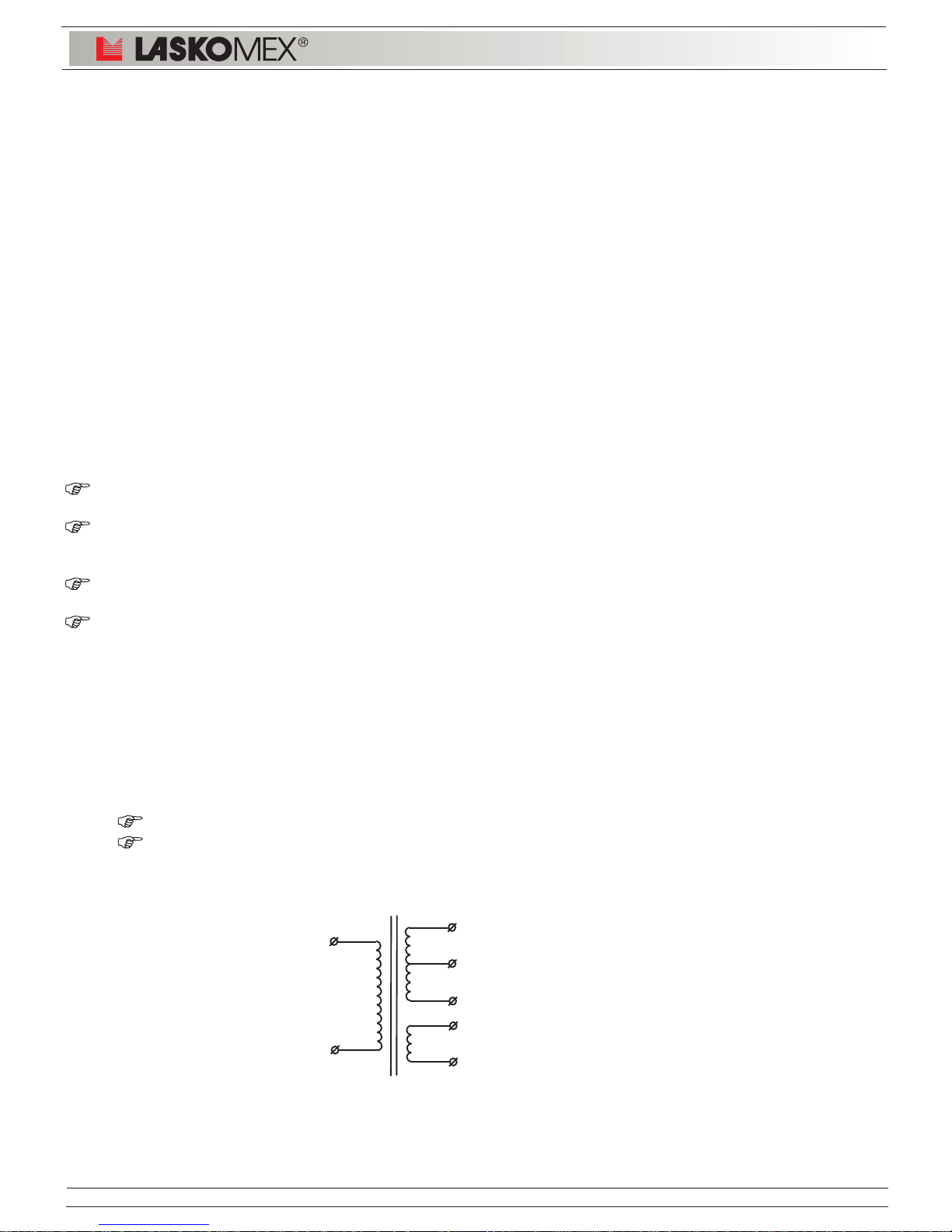
= ~230V
U
SEC1
= 12,5V / 0,8A
U
SEC1
+ U
SEC2
= 14,5V / 0,8A
U
SEC3
= 12V / 1A
brown
brown
Page 8
EC-2502
LASKOMEX PPUH, ul. D¹browskiego 249, 93-231 £ód, tel. (42) 671 88 00, fax (42) 671 88 88, e-mail: [email protected], http://www.laskomex.com.pl
7. CONFORMITY WITH PREVIOUS VERSIONS
Electronic cassette
Electronic cassettes EC-2502 can be used as replacements of electronic cassettes EC-2200,
EC-2200/U, EC-2200H, EC-2500/S, EC-2500/U, EC-2500/H, EC-2501/U and EC-2501H.
Electronic cassettes will co-operate with all previous versions of external panels for the mentioned
systems. If a three position display is installed in a panel, in electronic cassette settings an operation
of three position display should be activated (procedure P2, parameter 3C).
Other entry phone systems
System CD-2502 can cooperate with system CD-3100. This refers to situation when a few buildings
should be enclosed with a fence in which there will be more than one entrance. In such case at
the main entrance an entry phone CD-3100 should be installed (set consisted of EC-3100,
CP-3100 and supplier). Subordinate entrances should be connected in such a way as if entry phone
CD-2502 (line L+, L-) was installed at the main entrance.
If CD-3100 is connected with CD-2501 mode with building numbering will not operate.
8. FAULTS MESSAGES
CD-2502 entry phone can signal the following faults:
EC: Means that two or more infrared beams in keyboard are damaged or covered. Clean the
surface and sides of keyboard out of eventually dirt.
E2: Means short-circuit of uniphone line. Installation should be checked, short-circuit should
be eliminated or damaged uniphones should be replaced. By measuring current input on
uniphone line, the nature of fault can be determined.
E0: This message means that system EEPROM memory is damaged in the electronic cassette.
For repairs contact the service.
EEr:Means an error in recording or in reading memory with system settings or codes of coded
lock. For repairs contact the service.
9. TECHNICAL DATA
Power supply of EC-2502 electronic cassette:
Only from recommended power supply feeder ZS-K-25/01 or TSZZM 25/021M:
14,5V/0,8A (terminals AC1 and AC2)
12V/1A (terminals AC3 and AC4)
ZS-K-25/01 or TSZZM 25/021M power supply feeder of el. cassette - description of wires
Protection degree: IP20
Ambient temperature: (+5
÷ +40)oC
Page 9
Page 9
EC-2502
LASKOMEX PPUH, ul. D¹browskiego 249, 93-231 £ód, tel. (42) 671 88 00, fax (42) 671 88 88, e-mail: [email protected], http://www.laskomex.com.pl
10. DESCRIPTION OF TERMINALS
AC1 el. cassette supply 14,5V AC K1 (VS)* ext. panel supply (stabilized voltage +12V)
AC2 el. cassette supply 14,5V AC K2 (T)* digital data from/to ext. panel
AC3 electro-catch supply 12V AC K3 (GS)* digital mass
AC4 electro-catch supply 12V AC K4 (SP)* loudspeaker
GP mass of non-stabilized voltage K5 (GA)* analogue mass
VP non-stabilized voltage output K6 (MC)* microphone
GZA mass of electro-catch supply L+ uniphone line + (if works as EC-2502U)
VZA electro-catch supply communication line between cassette H and U
KZ output of key switching on el.-catch (if works as EC-2502H)
VZ electro-catch supply L- uniphone line - (if works as EC-2502U)
GZ mass of key switching on el.-catch LM master line (to connect main electronic cassette)
GS' mass of stabilized voltage NC free terminals (e.g. to connect segments of wire)
VS' stabilized voltage +12V X input of electronic key reader
PR door opening pushbutton B+ connection of accumulator (+)
CS selection of video signal source B- connection of accumulator (-)
(XX)* description on PCB
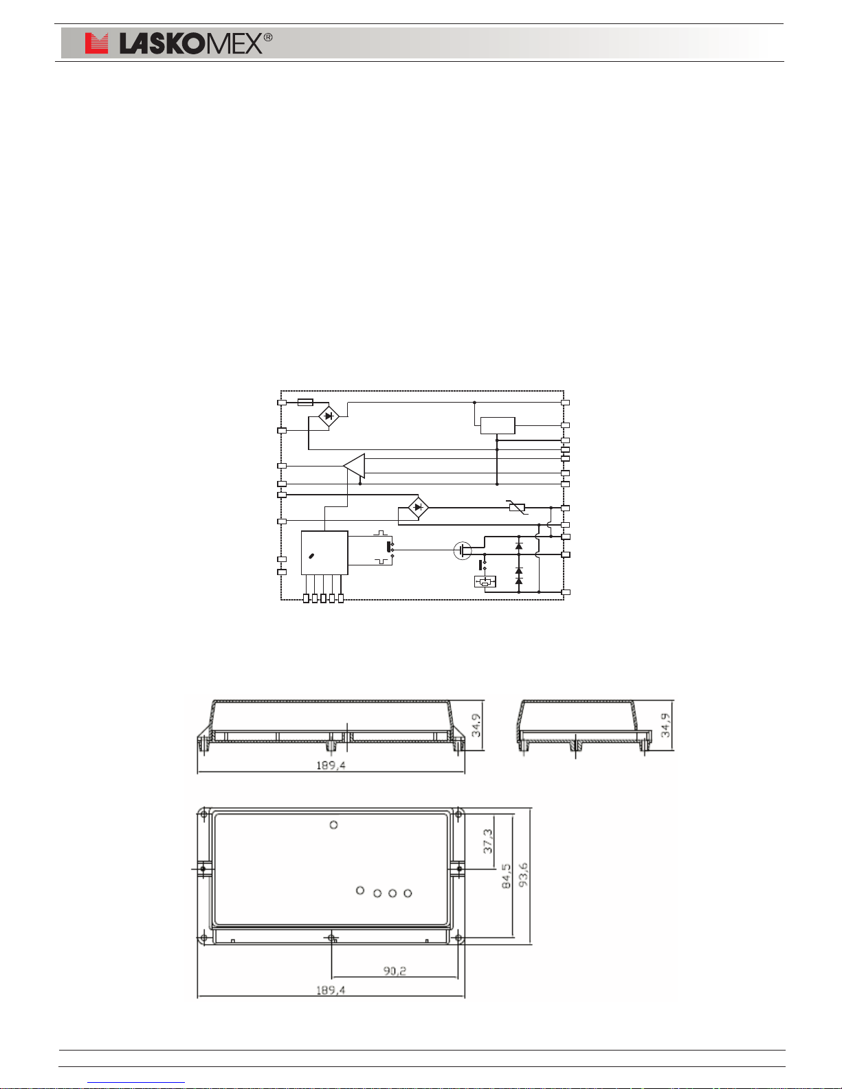
Figure 5: Electronic cassette block diagram
11. DIMENSIONS OF ELEMENTS
Figure 6: Dimensions of electronic cassette EC-2502
demagnetizing
ZT1
A
B
AC1
AC2
AC3
AC4
VP
VS
GS
GP
1,85 A
VZA
GZA
GA
VZ
KZ
GZ
el.catch
lock
+12V
stabilizer
L+
L-
MC
SP
PR
CS
T
GD
X
NC
NC
JP3
switching
key
uP
Page 10
to another distributor
or change-over
switch
Page 10
LML+L-K6K5K4K2K3K1XGS
NC1
NC2
X-
X+
C2-
C2+
V+
G
CS
C1-
C1+
LM
LM
L-
NOTE!
Terminals GZ, GZA and VZ, VZA
are connected permanently
inside electronic cassette.
!
EC-2502
LASKOMEX PPUH, ul. D¹browskiego 249, 93-231 £ód, tel. (42) 671 88 00, fax (42) 671 88 88, e-mail: [email protected], http://www.laskomex.com.pl
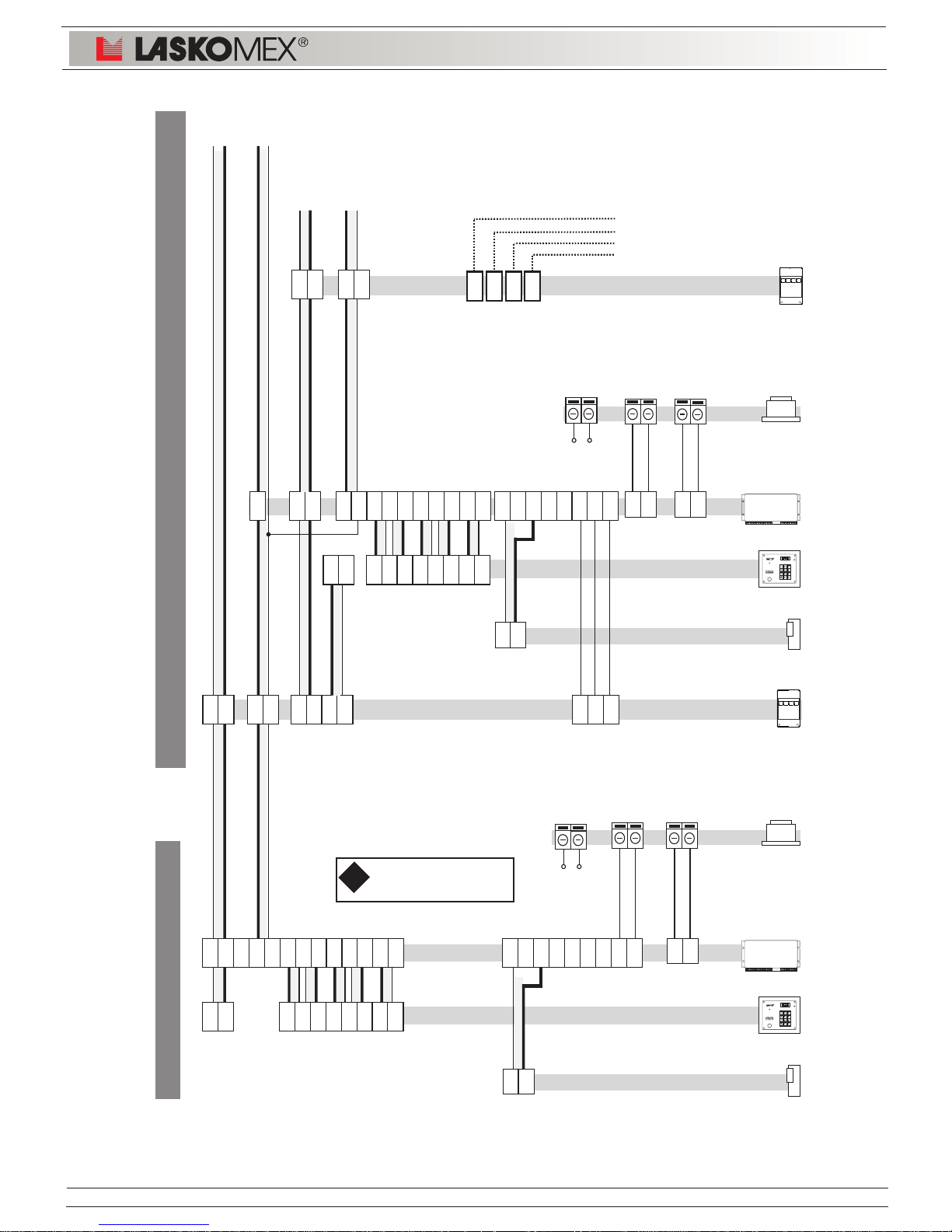
CVR-x
EC-2502/H
230 V AC
14,5 V AC
0,8 A
White
Brown
AC2
AC1
CP-xxxx
12 V AC
1 A
Brown
Brown
K6K5K4K2K3K1X
GX
GZVZKZ
GZA
VZAVPGP
AC4
AC3
C-
C+
EC-2502/U
230 V AC
14,5 V AC
0,8 A
White
Brown
AC2
AC1
CP-xxxx
12 V AC
1 A
AC4
AC3
Brown
Brown
L+L-K6K5K4K2K3K1X
GS
K6K5K4K2K3K1X
GX
GZVZKZ
GZA
VZA
VS
GS
NC1
NC2
C-
C+
CS
CVP-1
MAIN ENTRANCE
SUBORDINATE ENTRANCE
Electro-catch
MON1
MON2
MON3
MON4
power supply
of electronic
cassette
power supply
of electronic
cassette
Electro-catch
Figure 7: Entry phone CD-2502 video - multi entrance system
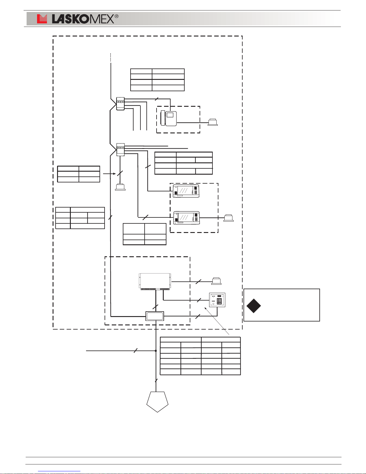
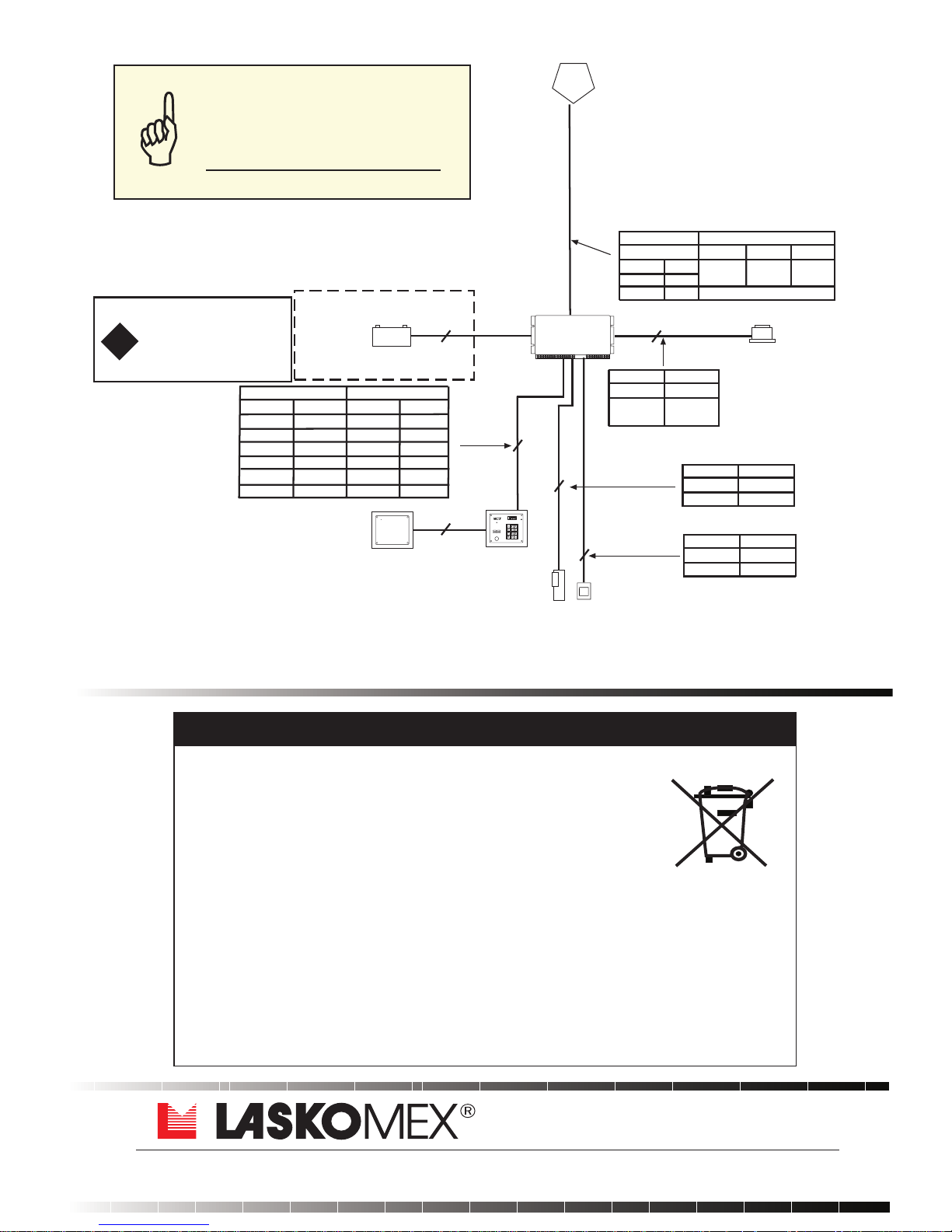
12. SELECTION OF WIRES AND CONNECTION DIAGRAMS
C-
C+
L+
L-
Page 11
CVP-1
Page 11
!
Note!
In panels CP-250xxR
should be increase the
number of wires connected
to terminal K3.
EC-2502/U
4
U
4
4
10
6 (LM,L+,L-,
V+,G,CS)
2 (C+,C-)
Distance
Clamps <15m
+15V, GND 1mm
2
Distance U-E
Clamps <50m <150m
L+,L-, 0,5mm 2x0,5mm
C+,C- 0,5mm
Distance
CVR-M
Clamps <30m
L+,L-,C+,C- 0,5mm
Distance CVR-M
Clamps <15m <30m
L+,L-,C+,C- 0,5mm
+15V,GND 0,5mm 2x0,5mm
Distance CVR-M
Clamps <30m
L+,L-,C+,C- 0,5mm
VC,GV/GC 0,5mm
6
6
4
4
M
M
any
YTKSY,UTP
YTKSY,UTP
YTKSY,UTP
2
E
the furthest
monitor
-
0,5mm
YTKSY,UTP,LAN T11,
XzTKMSpw
YTKSY,UTP,LAN T11, XzTKMXpw
YTKSY,UTP,LAN T11,XzTKMXpw
Clamps Distance
CP EC <15m <30m
K1,K4 K1,K4 0,5mm 2x 0,5mm
K2, K6 K2, K6 0,5mm 0,5mm
K3 K3 3x 0,5mm 5x 0,5mm
K5 K5 2x 0,5mm 2x 0,5mm
X, GX X, GS 0,5mm 0,5mm
Note!
In panels 250xxR
GX clamp leave
unconnected
EC-2502
LASKOMEX PPUH, ul. D¹browskiego 249, 93-231 £ód, tel. (42) 671 88 00, fax (42) 671 88 88, e-mail: [email protected], http://www.laskomex.com.pl
Staircase 1
to another
staircases
CP-25xx
DISTRIBUTION
CABINET
CVR-2
15V DC /4A
MVC-6x50
13,5V DC
MVC-6x50
to another
CVR
CVR-1
MV-645x
15V DC
MON1
MON2
MON3
MON4
MON4
MON3
MON2
MON1
power supply
of electronic
cassette
A
Figure 8: Selection of wires for entry phone CD-2502 in video version - part 1
Page 12
!
Note!
In panels CP-250xxR
should be increase the
number of wires connected
to terminal K3.
Distance
Clamps <15m
GZ,KZ 1mm
2
Distance
Clamps <15m
AC1,AC2, 1mm
2
AC3,AC4
Distance H-U
Clamps <50m <150m <250m
EC/H CVP-1
L+,L- LM,L- 0,5mm 2x0,5mm 3x0,5mm
NC1,NC2 C+,C- 0,5mm
EC-2502/H
4
12
H
any
any
2
2
OPTION
(B+,B-)
0,5mm
<1m
2
Distance
Clamps <15m
GS,PR 0,5mm
any
2(K1,K3)
YTKSY,UTP,LAN T11, XzTKMXpw
YTKSY,UTP,LAN T11, XzTKMXpw
Clamps Distance
CP EC <15m <30m
K1,K4 K1,K4 0,5mm 2x 0,5mm
K2, K6 K2, K6 0,5mm 0,5mm
K3 K3 3x 0,5mm 5x 0,5mm
K5 K5 2x 0,5mm 2x 0,5mm
X, GX X,GS 0,5mm 0,5mm
C+, C- NC1, NC2 0,5mm 0,5mm
Note!
In panels 250xxR
GX clamp leave
unconnected
List of collecting units of used Laskomex equipment is available on
www.laskomex.com.pl website or telephone No. +48 42 671 88 68.
Product packing should be removed according to environment protection regulations.
Remember!
Selective collection and recycling of used electronic and electric equipment
considerably contributes to the protection of human health and life as well as protection
of natural environment.
Return of packaging materials for the material recycling saves raw materials and
reduces generating of wastes.
This product was marked with a symbol of crossed dustbin according to
European Directive 2002/96/WE on used electric and electronic equipment.
Used equipment cannot be placed with other wastes from households.
Product user is obliged to give it to the firm which collects used electronic
or electric equipment such as local collection points, shops, places appointed
by the producer or commune waste collection units.
INSTRUCTION ON ENVIRONMENT PROTECTION
ul. D¹browskiego 249, 93-231 £ód, tel. +48 (42) 671 88 00, fax 671 88 88
e-mail: [email protected], http://www.laskomex.com.pl
CP-25xx
Electro-catch
Accumulator
12V/6Ah
Dooropen
button
List of
occupants
power supply
of electronic
cassette
V1.3 (2013-01-15)
A
Figure 9: Selection of wires for entry phone CD-2502 in video version - part 2
Full installation, usage
and programming
manual is available on
www.laskomex.com.pl
 Loading...