

Page 1

MODELO 2515
NOTAS
GARANTIA LIMITADA - NO ES VÁLIDA EN MÉXICO
SI NECESITA PIEZAS ADICIONALES FAVOR DE COMUNICARSE CON EL FABRICANTE POR LA GARANTIA DEL REMPLAZO DE
PIEZAS. INCLUYA UNA COPIA DE LA PRUEBA DE COMPRA, EL TIPO Y ESTILO DEL VENTILADOR, ESTA INFORMACION PUEDE
LOCALIZARLA EN LA PARTE DE ABAJO DE LA UNIDAD.
ESTE PRODUCTO ESTA GARANTIZADO CONTRA DEFECTOS DE FABRICACIONY/O MATERIALS POR UN AÑO A PARTIR DE LA FECHA
DE COMPRA. A NUESTRA OPCION, PIEZAS QUE SE COMPRUEBEN QUE ESTEN DEFECTUOSAS SERAN REPARADAS. REMPLAZADAS
O SE REMPLAZARA EL PRODUCTO POR COMPLETO.
SI NECESITA REPARACIONES ELECTRICAS O MECANICAS DURANTE EL PERIODO DE GARANTIA, ENVIE LA UNIDAD POR CORREO
O FLETE PAGADO AL CENTRO DE SERVICIO MAS CERCANO, LISTADO EN ESTA TARJETA.
SI SOLAMENTE NECESITA REMPLAZAR UNA PIEZA, TIENE QUE INDICAR EL TIPO Y ESTILO DEL VENTILADOR, ESTA INFORMACION SE
ENCUENTRA EN LA PARTE DE ABAJO DE LA UNIDAD. DE CUALQUIER FORMA, SE SOLICITA UNA COPIA DE LA PRUEBA DE COMPRA.
ESTA GARANTIA NO ES VALIDA SI EL DANO OCURRE DEBIDO A UN ACCIDENTE, MANEJO, INSTALACION, OPERSCION INCORRECTA,
DANO DURANTE EL TRANSPORTE, MALTRATO, USO INDEBIDO, REPARACIONES HECHAS O INTENTADAS NO AUTHORIZADAS, O EL
USO DEL PRODUCTO PARA FINES COMERCIALES.
TODAS LAS GARANTIAS EXPRESAS O IMPLICITAS, TIENEN UNA DURACION DE UN ANO A PARTIR DE LA FECHA DE COMPRA
ORIGINAL. ESTA GARANTIA EXPRESAS O IMPLICITAS, TIENEN UNA DURACION DE UN ANO A PARTIR DE LA FECHA DE COMPRA
ORIGINAL. ESTA GARANTIA NO CUBRE RESPONSABILIDADES POR DANOS PORTUITOS O CONSECUENTES POR NINGUNA CAUSA.
DADO QUE ALGUNOS ESTADOS NO PERMITEN NINGUNA LIMITACION EN LA DURACION DE UNA GARANTIA IMPLICADA, O LA
EXCLUSION O RESTRICCION DE DANOS FORTUITOS O CONSECUENTES. LA LIMITACION O EXCLUSION ANTES MENCIONADA
PODRIA SER NO VALIDA. ESTA GARANTIA EXTIENDE AL COMPRADOR ORIGINAL DERECHOS LEGALES ESPECIFICOS Y USTED
PODRIA TENER OTROS DERECHOS, LOS CUALES VARIAN DE UN ESTADO A OTRO.
PARA PIEZAS:
Para Repuestos Llame al: 1-800-233-0268. DE LUNES A VIERNES, DESDE LAS 8 DE LA MAÑANA A LAS 4 DE LA
TARDE, HORA DEL ESTE. "POR FAVOR NO DEVUELVA EL PRODUCTO AL SITIO DONDE LO COMPRÓ". Cuando
llame, refiérasa al tipo y estilo del producto (situados en la base del producto).
PARA OBTENER ASISTENCIA TÉCNICA Y LAS DIRECCIONES DEL CENTRO DE SERVICIO:
Para cualquier pregunta, comentarios o para obtener la dirección de su centro de servicio más cercano, SÍRVASE
LLAMAR A NUESTRO "TELÉFONO DE EMERGENCIA" GRATUITO AL 1-800-233-0268, DE LUNES A VIERNES,
DESDE LAS 8 DE LA MAÑANA A LAS 4 DE LA TARDE, HORA DEL ESTE. Cuando llame, refiérasa al nombre y número
de modelo del producto
Departamento de Servicio para Equipos • 300 Confederate Drive Franklin, TN 37064
¡POR FAVOR, NO ENVÍE EL PRODUCTO A ESTA DIRECCIÓN!
Para más información, por favor visite nuestro sitio web: www.laskoproducts.com
IMPORTANT INSTRUCTIONS -
OPERATING MANUAL
WIND TOWER® PLATINUM 40”
SPACE-SAVER FAN
MODEL 2515
READ AND SAVE THESE INSTRUCTIONS
READ CAREFULLY BEFORE ATTEMPTING TO ASSEMBLE, INSTALL, OPERATE OR MAINTAIN THE PRODUCT DESCRIBED.
PROTECT YOURSELF AND OTHERS BY OBSERVING ALL SAFETY INFORMATION. FAILURE TO COMPLY WITH
to reduce the risk of fire, electric shock and injury to persons,
1. Read all instructions before using Fan.
2. Make certain that the power source conforms to the electrical
requirements of the Fan.
3. Use this Fan only as described in this manual. Any other use
not recommended by the manufacturer ma y cause fire, electrical
shock, or injury to persons.
4. To reduce the risk of personal injury and electric shock, the
Fan should not be played with or placed where small
children can reach it.
5. Unplug power cord before installing, servicing, or
moving the Fan.
WARNING: DO NOT DEPEND UPON THE ON-OFF
SWITCH AS THE SOLE MEANS OF DISCONNECTING
POWER WHEN INSTALLING OR SERVICING THE FAN.
ALWAYS UNPLUG THE POWER CORD.
6. This Fan must NOT be used in potentially dangerous
locations such as flammable, explosive, chemical-laden
or wet atmospheres.
7. DO NOT use Fan in or near a window. Rain may create an
electrical hazard.
8. Completely reassemble Fan, according to instructions, before reconnecting to power supply.
WARNING: THIS APPLIANCE HAS A POLARIZED PLUG
(ONE BLADE IS WIDER THAN THE O THER). TO REDUCE
THE RISK OF ELECTRIC SHOCK, THIS PLUG IS
INTENDED TO FIT IN A POLARIZED OUTLET ONLY ONE
WAY . MATCH WIDE BLADE OF PLUG TO WIDE SLOT,
FULLY INSERT. IF THE PLUG DOES NOT FIT FULLY IN
THE OUTLET, REVERSE THE PLUG. IF IT STILL DOES
NOT FIT , CONT A CT A QU ALIFIED ELECTRICIAN. DO NO T
ATTEMPT TO DEFEAT THIS SAFETY FEATURE.
WARNING: THIS PLUG IS A SAFETY FEATURE. TO
REDUCE THE RISK OF FIRE, ELECTRIC SHOCK AND
INSTRUCTIONS COULD RESULT IN PERSONAL INJURY AND/OR PROPERTY DAMAGE!
RETAIN INSTRUCTIONS FOR FUTURE REFERENCE.
This Fan is for residential use onl y.
It is not intended to be used in commercial or industrial settings.
GENERAL SAFETY INFORMATION
When using electrical appliances,
basic precautions should always be followed
including the following:
PERSONAL INJURY, DO NOT REMOVE, REPLACE,
REPAIR OR TAMPER WITH THE ORIGINALLY SUPPLIED
PLUG. IF THE FAN DOES NOT FUNCTION PROPERLY, IT
MAY BE DUE TO THE SAFETY DEVICE INCORPORATED
IN THIS PLUG. RETURN TO AN AUTHORIZED SERVICE
CENTER OR CALL 800-233-0268, MONDAY - FRIDAY,
BETWEEN 8:30 AM AND 4:00 PM EST. IF THE PLUG
WARNING LABEL IS MISSING OR DAMAGED , CALL THE
TOLL FREE NUMBER FOR A REPLACEMENT LABEL.
9. Where possible, avoid the use of e xtension cords. If they must be
used, minimize the risk of overheating by ensuring that they are
UL listed. Never use a single extension cord to operate more
than one Fan.
10.Do not operate any Fan with a damaged cord or plug or after the
Fan malfunctions, has been dropped or damaged in an y manner .
Return Fan to authorized service facility for e xamination, electrical
or mechanical adjustment or repair.
11.Do not insert or allow fingers or foreign objects to enter any
ventilation or exhaust opening as it may cause an electric shoc k
or fire, or damage the Fan. Do not block or tamper with the Fan
in any manner while it is in operation.
12.Always place the Fan on a stable, flat, level surface when
operating, to avoid the chance of the Fan overturning. Locate
the Pow er Cord so the F an or other objects are not resting on it.
Do not run Power Cord under carpeting. Do not cover Power
Cord with throw rugs, runners, or the like. Arrange Power Cord
away from room traffic and where it will not be tripped over.
13.This Fan is not intended for use in wet or damp locations.
Never locate a Fan where it may fall into a bathtub or other
water container.
14. Do not use Fan outdoors.
WARNING: REDUCE THE RISK OF FIRE OR ELECTRIC
SHOCK – DO NOT USE THIS FAN WITH ANY SOLID STA TE
SPEED CONTROL DEVICES.
Rev. C 9/04
El manual imprimió en la China
8
2515ES
SAVE THESE INSTRUCTIONS
Rev. C 9/04 1
2515ES
Page 2
MODEL 2515
ASSEMBLY
1. For ease of assembly, lay the Fan down so that the front grill and
control panel are facing up.
2. Locate the
Place the
Column Supports
together to form the
3. Attach the
(4) 1/2” Long M5 Screws
Support Column Assembly
Motor Base. (Figure 1)
Column
Support
Cord
Channel
Power
Supply
Cord
4. Assemble the Bases by interlocking the
into the
A
Supply Cord
Base Assembly.
Support
Base B
Power Supply Cord
Power Supply Cord
. Snap the
Column Support Assembly. (Figure 1)
Column Support Assembly
. Make certain to align the
at the bottom on the Fan.
in the
Cord Channels
Column Supports
to the
Motor Base
with the
Locating Notch
Column Support Assembly
M5 X 1/2”
Screws
Boss Holes
Motor Base
Key
Column
Support
on
Support Base B
through the large hole in the center of the Support
(Figure 2)
Bosses
on
. Thread the
Support Base Assembly - Top View
Power Supply
Cord
Bosses
of the
firmly
Key
on the
on the
Locating
Notch
Figure 1
Support Base
Power
Support
Base A
Figure 2
with
5. Secure the
bottom of the base.
(2) #8 X 1/2” Screws
(Figure 3)
into the two holes in the
Support Base Assembly - Bottom View
Support
Base
Assembly
#8 X 1/2”
Screws
Power Supply
Cord
Figure 3
6. Align the
Assembly
support base should be towards the back of the Fan.
Assemble the
Support Assembly
any excess slack of the
Wire Locating Trough. (Figure 4)
Support Base Assembly
, noting that the cord channel on the bottom of the
Support Base Assembly
with
(4) 1” Long M5 Screws
Power Supply Cord
with the
Column Support
to the
and place it in the
Column
. Gently pull
Column to Base Assembly
Column
Support
Assembly
Support
Base
Assembly
M5 X 1”
Screws
Power
Supply
Cord
Wire
Locating
Trough
Figure 4
MODELO 2515
FUNCIONAMIENTO
Este Ventilador puede hacerse funcionar mediante los
Controles Manuales ubicados en la parte superior de la unidad
(como se muestra en la
(se muestra en la
1. Retire el Ventilador de la caja y arme según las instrucciones.
2. Coloque el Ventilador sobre una superficie firme y plana.
Figura 6
ADVERTENCIA: Los topes de plástico o de goma, como los
pies de esta unidad, pueden adherirse a los pisos de madera dura.
La unidad puede dejar un residuo que podría oscurecer, manchar
o producir defectos permanentes en la terminación de ciertos pisos
de madera dura.
3. Conecte el cable a un tomacorrientes eléctrico de 120 V~.
Asegúrese que el enchufe se introduzca firmemente en el
tomacorrientes.
4. Cuando el Ventilador esté enchufado, hará un “bip” que indique
que la unidad está encendida.
5. Encienda el Ventilador presionando el
Encendido
que la unidad fue encendida.
VELOCIDADES: Ajuste la velocidad del Ventilador oprimiendo
6.
el
Botón de Velocidad
de velocidad, cambiará la velocidad, de Baja (1) a Media (2) a
Alta (3). Cuando se lo conecta inicialmente , el Ventilador estar á
en V elocidad Baja. Cuando el V entilador se apaga y se enciende
nuevamente, la unidad volverá a la velocidad en la cual estaba
cuando fue apagado.
OSCILACIÓN: Oprima el
7.
y desactivar la función de oscilación.
8.
TEMPORIZADOR: La función temporizadora le permitirá
ajustar el tiempo de funcionamiento de Ω hora a 7 Ω horas,
con incrementos de Ω hora. Al oprimir el
( ), cambiará el tiempo de funcionamiento deseado . Cada v ez
para que presione el botón temporizador, el tiempo aumenta
en Ω hora. Después de llegar a las 71/2 horas, si oprime el
botón temporizador una vez más, el ventilador funcionará en
for ma continua. Las luces en el frente de la unidad se
encenderán apropiadamente con el lapso de tiempo para el
cual se activó el Ventilador.
( ). El Ventilador hará dos “bips” para indicar
Figura 5
).
( ). Cada vez que se oprima el botón
Botón de Oscilación
) o con el Control Remoto
Botón de
( ) para activar
Botón Temporizador
Compartimiento del
remoto control
MODO DE SUEÑO: Esta función per mite que la unidad se
9.
coloque en Modo de Sueño. Al oprimir el Botón de
( ) una vez, cambiará la velocidad de la Unidad a baja
Sueño
durante 6 horas continuas. Al apretar el Botón de
( ) una segunda vez, la unidad se colocará en 6 horas continuas.
El Botón de Oscilación (
en el Modo de Sueño. Al apretar cualquier otro botón
(Temporizador, Velocidad del Ventilador o de Encendido) se
cerrará el Modo de Sueño.
10.Para apagar el Ventilador, presione el
y desenchufe la unidad del tomacorrientes.
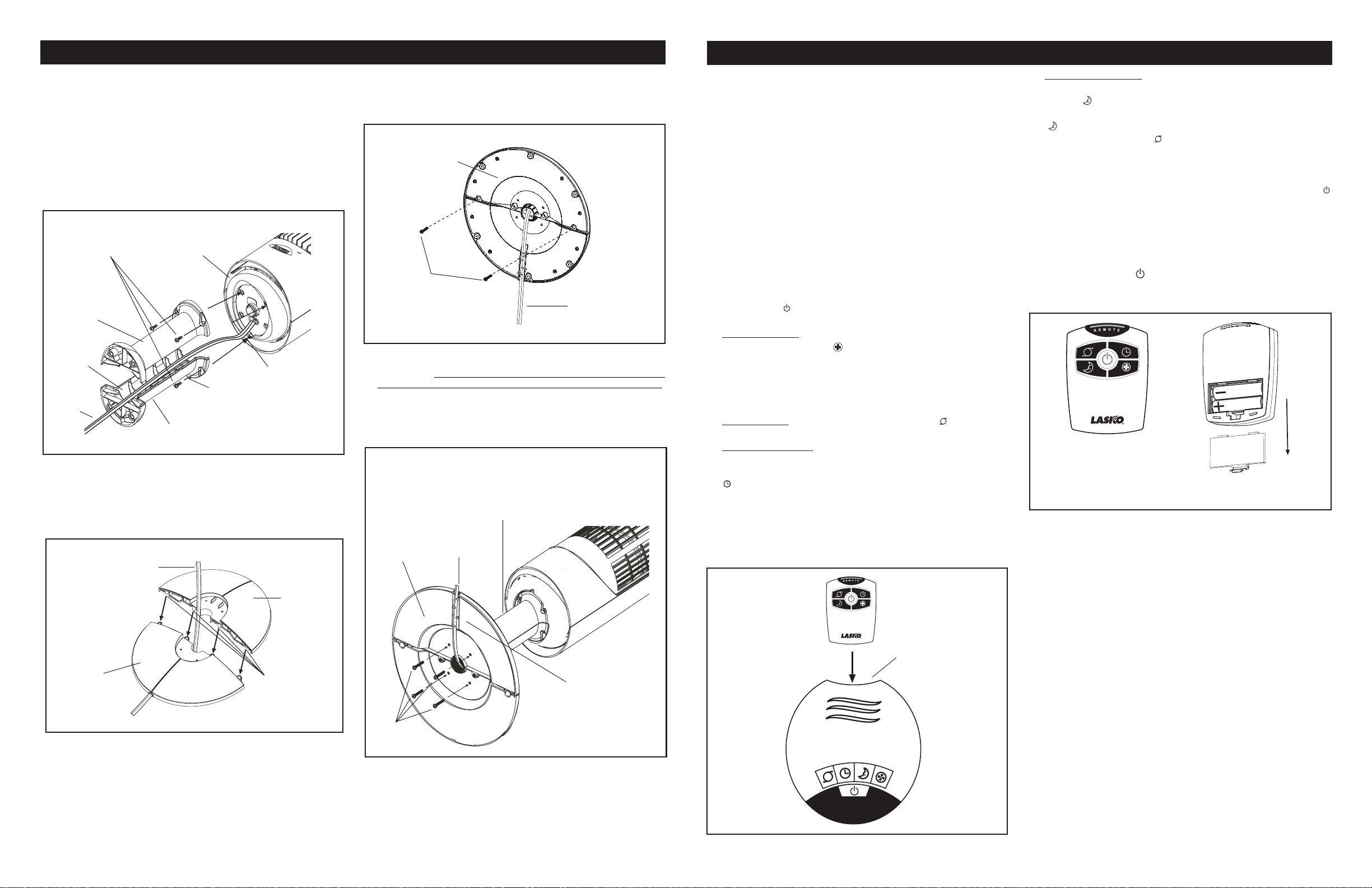
CONTROL REMOTO
1. Instale las dos baterías “AAA” que vienen con el equipo, como
se indica en la
2. El Botón De Encendido del Control Remoto está
identificado como (
3. Todas las funciones realizadas con el Control Remoto pueden
realizarse de igual forma con los Controles Manuales.
Vista Frontal del
Control Remoto
Si usted pierde su mando a distancia, por favor Cliente de llamada
Serive para ordenar un reaplacement en 1-800 -233-0268, de lunes
a viernes, entre las 8 a.m. y las 5 p .m. (Horario Estándar del Este de
los Estados Unidos).
Figura 6
) funcionará cuando el Ventilador esté
Botón de Encendido
(Figura 6)
.
).
Espalda De
Telemando
Modo de
Modo de Sueño
( )
Figura 6
MANTENIMIENTO
ADVERTENCIA: SIEMPRE DESCONECTE EL
ENCHUFE ANTES DE MOVER O PROPORCIONAR
SERVICIO AL VENTILADOR.
ADVERTENCIA: ¡NO SUMERJA EL VENTILADOR EN A GU A!
LIMPIEZA: Limpie el Ventilador con un aditamento de cepillo que
se ajuste a su máquina aspiradora. Esto eliminar á la suciedad y el
polvo que se pueden acumular con el paso del tiempo. NO INTENTE
DESARMAR EL VENTILADOR. Limpie el cuerpo del V entilador con
un paño suave.
ADVERTENCIA: No use gasolina, bencina, acetona,
limpiadores abrasivos, etc., puesto que eso dañará el V entilador ,
NUNCA use ALCOHOL o SOLVENTES.
SERVICIO: Cualquier otro servicio, con la excepción de
mantenimiento general por parte del usuario, deberá ser realizado
por un representante de servicio autorizado. Llamar al 1-800 -2330268, de lunes a viernes, entre las 8 a.m. y las 5 p.m. (Horario
Estándar del Este de los Estados Unidos), para averiguar la
dirección de su centro de servicio más cercano.
Figura 5
2
2515ES
Rev. C 9/04
GUARDADO: Guarde el Ventilador, con estas instrucciones, en un
lugar fresco y seco.
7
2515ESRev. C 9/04
Page 3

MODELO 2515
ARMADO
1. Para facilitar el armado, recueste el Ventilador de modo que la
parrilla negra y el tablero de control den hacia arriba.
2. Localice el
Coloque el
Soportes De Columna
Columna
Soportes De Columna
3. Una el
con
(4) Tornillos M5 de 1/2”de largo
Llave
Localizadora
Cable Eléctrico
Cable Eléctrico
el uno con el otro de modo de formar un
Conjunto De Soportes De Columna
del
Conjunto De Soportes De Columna
de la
Base Del Motor. (Figura 1)
Conjunto De Soportes De Columna
Tornillos
M5 de 1/2”
Soportes
De Columna
Canales
Para Cable
Cable
Eléctrico
4. Arme las Bases de Soporte, introduciendo las
de Soporte A
. Pase el
B
centro del Conjunto de la Base de Soporte.
en los
Cable de Electricidad
Orificios De Copas
Conjunto de la Base de Soporte -
Vista des de Arriba
Cable
Eléctrico
en la par te inferior del Ventilador.
en los
. Encaje firmemente los
.
(Figura 1)
Base Del
Soportes
De Columna
Canales Para Cable
a la
Base Del Motor
. Cerciórese de alinear la
Motor
Llave
de la
por el orificio grande en el
con la
Muesca
Localizadora
Copas
Base de Soporte
(Figura 2)
Soportes De
Conjunto De
Base de
Soporte A
Muesca
Figura 1
en la
de los
Base
5. Fije los
encuentran en la parte inferior de la base.
Tornillos (2) #8 X 1/2”
en los cuatro orificios que se
(Figura 3)
Conjunto de la Base de Soporte -
Vista des de Abajo
Conjunto
de la Base
de Soporte
#8 X 1/2”
Tornillos
Cable
Eléctrico
Figura 3
6. Alinee el
Columna
inferior de la base de soporte esté orientado hacia la par te
posterior del Ventilador. Ensamble el
Soporte
los
excesiva del
Conductor de Cable
Conjunto de la Base de Soporte
, cerciorándose de que el canal del cable en la par te
con el
Tornillos M5 de (4) 1”
Conjunto del Soporte de Columna
de largo . Jale con cuidado toda holgura
Cable de Electricidad
.
(Figura 4)
e introdúzcala por el
con el
Conjunto de la Base de
Soporte de
utilizando
Conjunto de Columna Para la Base
Conjunto De
Soportes De
Columna
Conjunto
de la Base
de Soporte
Cable
Eléctrico
Canal
MODEL 2535
MODEL 2515
OPERATION
This Fan ma y be operated by the Man ual Controls located on top
of the unit (as shown in
(shown in
1. Remove the Fan from the carton and assemble as instructed.
2. Place the Fan on a firm, level surface.
Figure 6)
WARNING: Plastic or rubber tabs, like the feet on this unit, may
stick to hardwood floors. The unit may leave a residue that could
darken, stain or leave permanent blemishes on the finish of certain
hardwood floors.
3. Plug the power supply cord into a 120 V~ electrical outlet. Be
sure plug fits tightly in outlet.
4. When the Fan is plugged in, there will be a “beep” to indicate
there is power to the unit.
5. Turn the Fan ON by pressing the
“beep” twice to indicate that the unit has been turned ON.
SPEEDS: Press the
6.
setting. Each time the Fan Speed Button is pressed, the speed
will change from Low (1), to Medium (2), to High (3). When intially
plugged in, the Fan will be in Low Speed. When the F an is turned
OFF and ON again, the unit will resume the speed at which it
was turned OFF.
OSCILLATION: Press the
7.
stop the oscillation function.
8. TIMER: The timer function allows the unit to be set to operate
for a length of time from 1/2 hour to 7 1/2 hours, in increments of
a 1/2 hour. Press the
desired. Each time the timer button is pressed, the time is
increased by 1/2 hour. After reaching 7 1/2 hours, pressing the
timer button once more will reset the Fan to contin uous running.
The lights on the front of the unit will light up appropriately with
the length of time that the Fan is set for.
SLEEP: This function allows the unit to be set in Sleep Mode.
9.
Pressing the
6 continuous hours. Pressing the
time will reset the unit to 6 continuous hours. The Oscillation
Button ( ) will function when the Fan is in Sleep Mode. Pressing
any other button (Timer, Fan Speed or the Power Button) will
shut off the Sleep Mode.
10. To turn the Fan OFF, press the
the unit from the electrical outlet.
Sleep Button
Figure 5
.
Fan Speed Button
Oscillation Button
Timer Button
( ) once will set the unit on Low for
) or by the Remote Control
Power Button
( ) to set the length of time
Sleep Button
Power Button
( ). The Fan will
( ) to desired speed
( ) to start and
( ) a second
( ) and unplug
REMOTE CONTROL
1. Install the two “AAA” batteries supplied as shown in
2. The Remote Control Power Button is labeled as (
3. All the functions performed with the Remote Control work
identically to the Manual Controls.
Front of
Remote
If you lose your remote control, please call Customer Service to
order a replacement at 1-800-233-0268, Monday through Friday,
between the hours of 8:00 a.m. and 5:00 p.m. EST.
(Figure 6)
Figure 6
).
Back of
Remote
Figure 6
.
MAINTENANCE
WARNING: ALWAYS UNPLUG THE CORD BEFORE MOVING
OR SERVICING.
WARNING: DO NOT IMMERSE FAN IN WATER!
CLEANING: Clean the Fan with the vacuum brush attachment
on your vacuum cleaner. This will remove dirt and lint that may
accumulate over time. DO NOT ATTEMPT TO TAKE APART
FAN. Clean the body of the Fan with a soft cloth.
CAUTION: Do not use gasoline, benzine, thinner , harsh c lean-
ers, etc. as they may damage the Fan. NEVER use ALCOHOL
OR SOLVENTS.
SERVICING: All other servicing, with the exception of general user
maintenance, should be performed by an authorized service representative. Call 1-800-233-0268, Monday through Friday, between
the hours of 8:00 a.m. and 5:00 p.m. EST for the location of your
nearest service center.
STORAGE: Store the Fan, with these instructions, in a cool, dry place.
Base de
Soporte B
Rev. C 9/04
Copas
Figura 2
6
M5 X 1”
Tornillos
Canal
Conductor
de Cable
Figura 4
2515ES
Rev. C 9/04
Remote Storage
Figure 5
3
2515ES
Page 4

MODEL 2515
NOTES
INSTRUCCIONES IMPORTANTES -
MANUAL DE USO
LIMITED WARRANTY - NOT VALID IN MEXICO
SHOULD ACCESSORY PARTS BE NEEDED, CONTACT THE MANUFACTURER FOR IN-WARRANTY REPLACEMENT PARTS. A
COPY OF PROOF-OF-PURCHASE MUST BE INCLUDED ALONG WITH THE TYPE AND STYLE, WHICH IS LOCATED ON THE
BOTTOM OF YOUR APPLIANCE.
This product is warranted for one year from the date of original purchase against defects in workmanship and/or materials. At our option, parts
that prove to be defective will either be repaired or replaced or the whole product will be replaced.
Should electrical or mechanical repair become necessary during the warranty period, send your complete product, postage or freight pre-paid
to the nearest service center. Call the number below for the service station nearest you.
Should a part need replacement, you must give us the type and style of your appliance. You will find this at the bottom of the appliance. In
either case, a copy of your proof of purchase is requested.
This warranty does not apply if the damage occurs because of accident, improper handling or operation, shipping damage, abuse, misuse,
unauthorized repairs made or attempted, or the use of the product for commercial service.
ALL WARRANTIES, EXPRESSED OR IMPLIED, LAST FOR ONE YEAR FROM THE DATE OF ORIGINAL PURCHASE. THIS
WARRANTY DOES NOT COVER LIABILITY FOR INCIDENTAL OR CONSEQUENTIAL DAMAGES FOR ANY CAUSE WHATSOEVER.
Some states do not allow limitations on how long any implied warranty lasts, or the exclusion or limitation of incidental or consequential
damages, so that the above limitations and exclusions may not apply to you. This warranty gives you specific legal rights. You may also have
other rights which vary from state to state.
FOR PARTS:
For Replacement Parts please call: 1-800-233-0268. MONDAY THROUGH FRIDAY, BETWEEN THE HOURS OF 8
AM AND 4 PM EST. "PLEASE DO NOT RETURN PRODUCT TO PLACE OF PURCHASE." Reference the type and
style of product (located on the underside of the product) when you call.
FOR TECHNICAL ASSISTANCE and SERVICE CENTER LOCATIONS:
For any questions, comments or the location of your nearest service center, PLEASE CALL OUR TOLL-FREE
"HOTLINE" AT 1-800-233-0268. MONDAY THROUGH FRIDAY, BETWEEN THE HOURS OF 8 AM AND 5 PM EST.
Please reference product name and model no. when you call.
Appliance Service Dept. • 300 Confederate Drive Franklin, TN 37064 PLEASE DO NOT SEND PRODUCT TO THIS LOCATION!
For more information please visit our website: www.laskoproducts.com
Manual Printed in China
Rev. C 9 /04
4
2515ES
VENTILADOR AHORRATIVO EN ESPACIO
®
DE 40” WIND TOWER
PLATINUM
MODELO 2515
LEA Y GUARDE ESTAS INSTRUCCIONES
LEA CUIDADOSAMENTE LAS INSTRUCCIONES ANTES DE INTENTAR ARMAR, INSTALAR, USAR O DAR
PROTÉJASE A SÍ MISMO Y A LOS DEMÁS CUMPLIENDO CON TODA LA INFORMACIÓN DE SEGURIDAD. EL NO
SEGUIR LAS INSTRUCCIONES PODRÍA RESULTAR EN LESIONES PERSONALES Y/O DAÑOS A LA PROPIEDAD.
CONSERVE LAS INSTRUCCIONES COMO FUTURA REFERENCIA.
Este Ventilador es para uso residencial únicamente.
No está destinado para uso en ambientes comerciales o industriales.
INFORMACIÓN GENERAL DE SEGURIDAD
Al usar aparatos eléctricos, las precauciones básicas de seguridad deberan
siempre de seguirse para reducir el riesgo de incendio, choque eléctrico, y
daño a personas, incluyenda las siguientes:
1. Lea todas las instrucciones antes de utilizar el Ventilador.
2. Cerciórese de que la fuente de poder sea compatible con las
demandas eléctricas del Ventilador.
3. Use este V entilador sólo en la forma que se describe en el manual.
Cualquier otro uso no recomendado por el fabricante podría
ocasionar un incendio, golpes de electricidad o lesiones a personas.
4. Para disminuir el riesgo de lesiones físicas y golpes de
electricidad, no debe jugarse con el ventilador no deberá éste
ser ubicado al alcance de los niños pequeños.
5. Desenchufe el cable eléctrico antes de instalar, proporcionar
servicio o mover el Ventilador.
ADVERTENCIA: NO DEPENDA DEL INTERRUPTOR DE
ENCENDIDO-APAGADO COMO EL ÚNICO MEDIO PARA
DESCONECTAR LA POTENCIA AL INSTALAR O
PROPORCIONARLE SERVICIO AL VENTILADOR.
DESENCHUFE SIEMPRE EL CABLE ELÉCTRICO.
6. Este V entilador NO debe usarse en ubicaciones potencialmente
peligrosas, tales como en ambientes inflamables, explosivos,
cargados de sustancias químicas o húmedos.
7. NO use el V entilador en o cerca de una ventana. La lluvia puede
generar riesgos eléctricos.
8. Vuelva a armar el ventilador por completo, siguiendo las
instrucciones, antes de reconectarse a la fuente de poder.
ADVERTENCIA: ESTE ARTEFA CTO POSEE UN ENCHUFE
POLARIZADO (UNA ESPIGA ES MÁS ANCHA QUE LA
OTRA). PARA DISMINUIR EL PELIGRO DE GOLPES DE
ELECTRICIDAD , ESTE ENCHUFE DEBERÁ INTRODUCIRSE
EN UN TOMACORRIENTE POLARIZADO SÓLO DE UNA
FORMA. HAGA ENCAJ AR TOTALMENTE LA ESPIGA ANCHA
DEL ENCHUFE EN LA RANURA ANCHA. SI EL ENCHUFE
NO ENCAJA POR COMPLETO EN EL TOMACORRIENTE,
INVIERTA EL ENCHUFE. SI AUN ASÍ NO ENCAJA,
CONT ACTE A UN ELECTRICIST A CALIFICADO . NO INTENTE
BURLAR ESTA FUNCIÓN DE SEGURIDAD.
ADVERTENCIA: ESTE ENCHUFE ES UNA MEDIDA DE
SEGURIDAD . PARA REDUCIR EL RIESGO DE INCENDIO ,
CHOQUE ELÉCTRICO Y LESIONES PERSONALES, NO
QUITE, NI REEMPLACE, NI REPARE O ALTERE EL
ENCHUFE QUE SE PROVEE ORIGINALMENTE. SI EL
CONSERVE ESTAS INSTRUCCIONES
Rev. C 9/04
MANTENIMIENTO AL PRODUCTO DESCRITO.
VENTILADOR NO FUNCIONA CORRECT AMENTE, PUEDE
DEBERSE AL DISPOSITIVO DE SEGURIDAD
INCORPORADO EN ESTE ENCHUFE. REGRESE A UN
CENTRO DE SER VICIOS AUTORIZADO O LLAME AL 800233-0268, DE LUNES A VIERNES ENTRE LAS 8.30 A.M. Y
LAS 4.00 P.M. EST. SI LA ETIQUETA DE ADVERTENCIA
DEL ENCHUFE FALTA O ESTA DAÑADA, LLAME AL
NÚMERO DE CONSULTA GRATUITO PARA PEDIR UNA
ETIQUETA DE REEMPLAZO.
9. De ser posible, evite el uso de cables de extensión. Si debieran
usarse, minimice el riesgo de sobrecalentamiento procurando que
estén aprobados por UL. Nunca use un solo cable de extensión
para hacer funcionar más de un Ventilador.
10.No haga funcionar ningún Ventilador con un cable o enchufe
dañado o después de que el ventilador presente algún desperfecto
o haya sido dejado caer o sufriera cualquier tipo de daño . Reg rese
el V entilador a un servicio de reparación autorizado para examinar
el V entilador , efectuarle ajustes eléctricos o mecánicos o repararlo.
11.No introduzca ni permita que se introduzcan dedos u objetos
extraños en ninguna abertura de ventilación o escape, puesto
que podría provocar un golpe de electricidad, incendio, o daños
al ventilador. No bloquee ni manipule el Ventilador de ninguna
manera mientras esté en funcionamiento.
12.Siempre coloque el V entilador sobre una superficie, estab le, plana
y horizontal mientras esté en funcionamiento, para evitar la
posibilidad de que el Ventilador se dé vuelta. Ubique el cable
eléctrico de tal modo que el ventilador u otros objetos no
descansen sobre él. No disponga el cable eléctrico debajo de
alfombras. No cubra el cable eléctrico con tapetes, alfombras
continuas u objetos similares. Coloque el cable eléctrico fuera
del paso de las personas y donde nadie se tropiece con el mismo.
13.Este V entilador no ha sido diseñado para usarse en lugares mojados
o húmedos. Nunca coloque un V entilador donde quepa la posibilidad
de que caiga en una bañera u otro recipiente con agua.
14.No use el Ventilador en exteriores.
ADVERTENCIA: DISMINUYA EL RIESGO DE INCENDIO
O GOLPES DE ELECTRICIDAD – NO USE ESTE
VENTILADOR CON ARTEFACTOS DE CONTROL DE
VELOCIDAD EN ESTADO SÓLIDO.
5
2515ES
 Loading...