

LIMITED WARRANTY
SHOULD ACCESSORY PARTS BE NEEDED, CONTACT THE MANUFACTURER FOR IN-WARRANTY REPLACEMENT
PARTS. A COPY OF PROOF-OF-PURCHASE MUST BE INCLUDED ALONG WITH THE TYPE AND STYLE, WHICH IS
LOCATED ON THE BOTTOM OF YOUR APPLIANCE.
This product is warranted for one year from the date of original purchase against defects in workmanship and/or materials. At
our option, parts that prove to be defective will either be repaired or replaced or the whole product will be replaced.
Should electrical or mechanical repair become necessary during the warranty period, send your complete product, postage or
freight pre-paid to the nearest service center. Call the number below for the service station nearest you.
Should a part need replacement, you must give us the type and style of your appliance. You will find this at the bottom of the
appliance. In either case, a copy of your proof of purchase is requested.
This warranty does not apply if the damage occurs because of accident, improper handling or operation, shipping damage,
abuse, misuse, unauthorized repairs made or attempted, or the use of the product for commercial service.
ALL WARRANTIES, EXPRESSED OR IMPLIED, LAST FOR ONE YEAR FROM THE DATE OF ORIGINAL PURCHASE. THIS
WARRANTY DOES NOT COVER LIABILITY FOR INCIDENTAL OR CONSEQUENTIAL DAMAGES FOR ANY CAUSE
WHATSOEVER.
Some states do not allow limitations on how long any implied warranty lasts, or the exclusion or limitation of incidental or
consequential damages, so that the above limitations and exclusions may not apply to you. This warranty gives you specific
legal rights. You may also have other rights which vary from state to state.
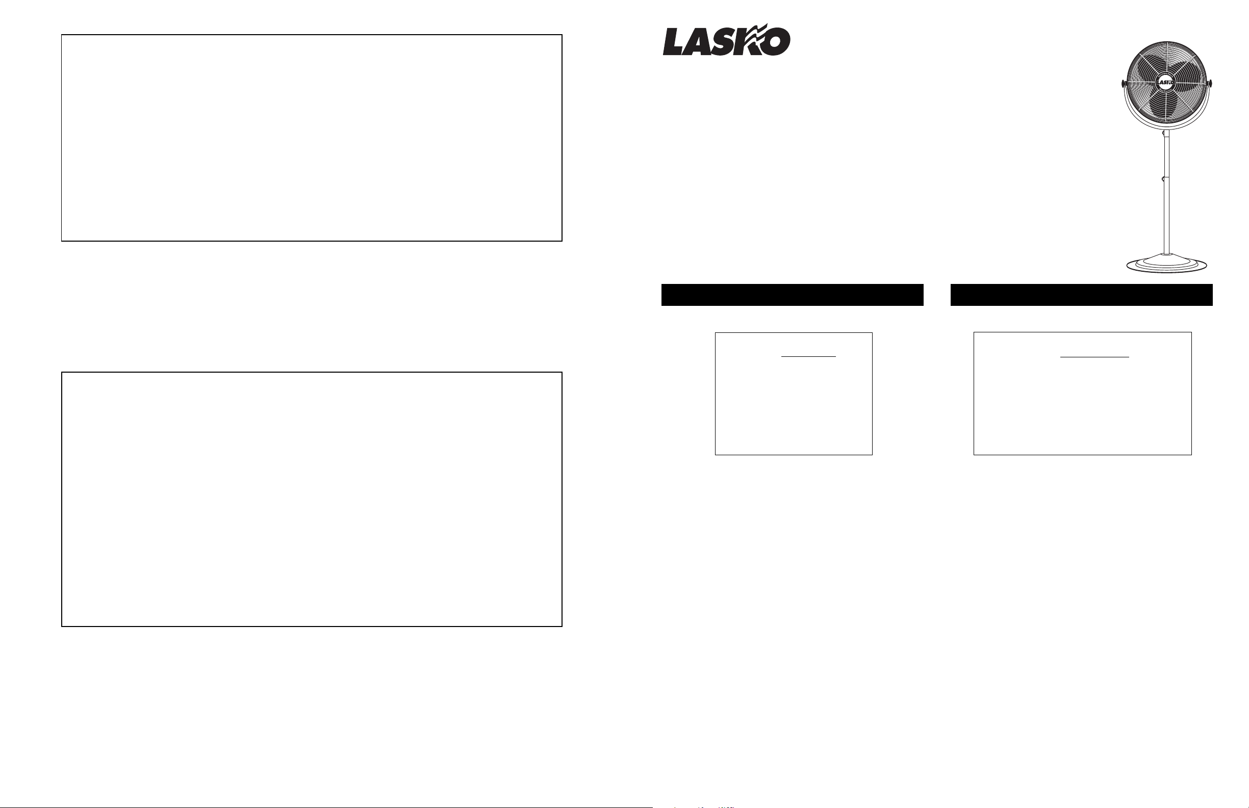
Innovators in Home Comfort
TM
20 INCH HIGH VELOCITY
PEDESTAL FAN
Model 2420
VENTILADOR DE ALTA
VELOCIDAD DE 50,8 CM
FOR PARTS:
Check package contents. If parts are missing, or replacement parts required, please call our PARTS DEPARTMENT TOLL-FREE
AT 1-800-966-2028. MONDAY THROUGH FRIDAY, BETWEEN THE HOURS OF 8 AM AND 4 PM EST. "PLEASE DO NOT
RETURN PRODUCT TO PLACE OF PURCHASE." Reference the type and style of product (located on motor) when you call.
FOR TECHNICAL ASSISTANCE and SERVICE CENTER LOCATIONS:
For any questions, comments or the location of your nearest service center, PLEASE CALL OUR TOLL-FREE "HOTLINE" AT 1-800233-0268. MONDAY THROUGH FRIDAY, BETWEEN THE HOURS OF 8 AM AND 5 PM EST. Please reference product name and
model no. when you call.
Appliance Service Dept. • P.O. Box 569 Franklin, TN 37065-0569 PLEASE DO NOT SEND PRODUCT TO THIS LOCATION!
GARANTIA LIMITADA
SI NECESITA PIEZAS ADICIONALES FAVOR DE COMUNICARSE CON EL FABRICANTE POR LA GARANTIA DEL
REMPLAZO DE PIEZAS. INCLUYA UNA COPIA DE LA PRUEBA DE COMPRA, EL TIPO Y ESTILO DEL VENTILADOR,
ESTA INFORMACION PUEDE LOCALIZARLA EN LA PARTE DE ABAJO DE LA UNIDAD.
ESTE PRODUCTO ESTA GARANTIZADO CONTRA DEFECTOS DE FABRICACIONY/O MATERIALS POR UN AÑO A
PARTIR DE LA FECHA DE COMPRA. A NUESTRA OPCION, PIEZAS QUE SE COMPRUEBEN QUE ESTEN
DEFECTUOSAS SERAN REPARADAS. REMPLAZADAS O SE REMPLAZARA EL PRODUCTO POR COMPLETO.
SI NECESITA REPARACIONES ELECTRICAS O MECANICAS DURANTE EL PERIODO DE GARANTIA, ENVIE LA UNIDAD
POR CORREO O FLETE PAGADO AL CENTRO DE SERVICIO MAS CERCANO, LISTADO EN ESTA TARJETA.
SI SOLAMENTE NECESITA REMPLAZAR UNA PIEZA, TIENE QUE INDICAR EL TIPO Y ESTILO DEL VENTILADOR, ESTA
INFORMACION SE ENCUENTRA EN LA PARTE DE ABAJO DE LA UNIDAD. DE CUALQUIER FORMA, SE SOLICITA UNA
COPIA DE LA PRUEBA DE COMPRA.
ESTA GARANTIA NO ES VALIDA SI EL DANO OCURRE DEBIDO A UN ACCIDENTE, MANEJO, INSTALACION,
OPERSCION INCORRECTA, DANO DURANTE EL TRANSPORTE, MALTRATO, USO INDEBIDO, REPARACIONES
HECHAS O INTENTADAS NO AUTHORIZADAS, O EL USO DEL PRODUCTO PARA FINES COMERCIALES. TODAS LAS
GARANTIAS EXPRESAS O IMPLICITAS, TIENEN UNA DURACION DE UN ANO A PARTIR DE LA FECHA DE COMPRA
ORIGINAL. ESTA GARANTIA EXPRESAS O IMPLICITAS, TIENEN UNA DURACION DE UN ANO A PARTIR DE LA FECHA
DE COMPRA ORIGINAL. ESTA GARANTIA NO CUBRE RESPONSABILIDADES POR DANOS PORTUITOS O
CONSECUENTES POR NINGUNA CAUSA. DADO QUE ALGUNOS ESTADOS NO PERMITEN NINGUNA LIMITACION EN
LA DURACION DE UNA GARANTIA IMPLICADA, O LA EXCLUSION O RESTRICCION DE DANOS FORTUITOS O
CONSECUENTES. LA LIMITACION O EXCLUSION ANTES MENCIONADA PODRIA SER NO VALIDA. ESTA GARANTIA
EXTIENDE AL COMPRADOR ORIGINAL DERECHOS LEGALES ESPECIFICOS Y USTED PODRIA TENER OTROS
DERECHOS, LOS CUALES VARIAN DE UN ESTADO A OTRO.
PARA PIEZAS:
Examine el contenido del empaque. Si faltan piezas, o los repuestos requerir, sírvase llamar al TELÉFONE GRATUITO DEL
DEPARTAMENTO DE REPUESTOS, AL 1-800-966-2028. DE LUNES A VIERNES, DESDE LAS 8 DE LA MAÑANA A LAS 4 DE
LA TARDE, HORA DEL ESTE. "POR FAVOR NO DEVUELVA EL PRODUCTO AL SITIO DONDE LO COMPRÓ". Cuando llame,
refiérasa al tipo y estilo del producto (situados en la motor).
PARA OBTENER ASISTENCIA TÉCNICA Y LAS DIRECCIONES DEL CENTRO DE SERVICIO:
Para cualquier pregunta, comentarios o para obtener la dirección de su centro de servicio más cercano, SÍRVASE LLAMAR A
NUESTRO "TELÉFONO DE EMERGENCIA" GRATUITO AL 1-800-233-0268, DE LUNES A VIERNES, DESDE LAS 8 DE LA
MAÑANA A LAS 4 DE LA TARDE, HORA DEL ESTE. Cuando llame, refiérasa al nombre y número de modelo del producto.
Departamento de Servicio para Equipos • P.O. Box 569 Franklin, TN 37065-0569¡POR FAVOR, NO ENVÍE EL PRODUCTO A ESTA
DIRECCIÓN!
Rev. A 9/98 2084439
4
Modelo 2420
IMPORTANT SAFETY INSTRUCTIONS
READ AND SAVE THESE INSTRUCTIONS
Supplied in PARTS BAG :
(2) Pipe Knobs (Small)
(2) Grill Knobs (Large)
(1) Hex Wrench
(1) Bolt 5/16 - 18 x 1-1/4"
(2) Rubber Spacers
(1) 5/16" Split Lockwasher
RULES FOR SAFE OPERATION
1. Never insert fingers, pencils, or any other foreign object
through grill when Fan is running.
2. Warning: To reduce the risk of fire or electrical shock, or
personal injury:
a. Do not use this Fan with any solid state speed control
device.
b. Unplug Fan before cleaning or servicing.
c. Completely reassemble Fan after cleaning or
servicing, according to instructions, before
reconnecting to power supply.
3. To avoid the possibility of overturning the Fan, ensure
that it is operating on a stable, level surface.
4. Do not use in a wet or explosive atmosphere, such as
may be present near food preparation or combustible
work areas.
5. Caution: Because of size and weight of this Fan,
make sure all parts are COMPLETELY ASSEMBLED
ACCORDING TO INSTRUCTIONS. Failure to do so
could result in Fan coming apart during operation and/or
personal injury.
CAUTION: LAY FAN ON ITS SIDE OR HOLD TOP OF
FAN FIRMLY WHEN ADJUSTING HEIGHT. INJURY MAY
OCCUR IF FAN IS NOT SUPPORTED.
Rev. A 9/98 20844391
INSTRUCCIONES IMPORTANTES DE SEGURIDAD
LEA Y CONSERVE ESTAS INSTRUCCIONES
Suministros por
(2) Perilla del Tubo (Pequeña)
(2) Perilla de la Rejilla (Grande)
(1) Llave Hexagonal
(1) Perno de 5/16 - 18 x 1-1/4"
(2) Espaciadores de Caucho
(1) Arandela de Seguridad Rayada-5/16"
PIEZAS BOLSA :
NORMAS PARA UNA CORRECTA UTILIZACION
1. Nunca introduzca los dedos, lapices, o cualquier otro objeto
extrano a traves de la rejilla cuando el Ventilador este en marcha.
2. Advertencia: Para reducir el riesgo de incendio, descarga
electrica o danos personales:
a. No utilice este Ventilador sin ningun dispositivo electronico
de control de velocidad.
el
b. Desenchufe
mantenimiento.
c. Vuelva a montar completamente el Ventilador despues de
su limpieza y servicio, de acuerdo con las instrucciones,
antes de volver a conectarlo.
3. Para evitar la posibilidad de que el Ventilador se vuelque,
asegurese de que esta funcionando sobre una superficie
estable y nivelada.
4. No lo utilice en un ambiente explosivo o mojado, como pueden
ser lugares donde se cocina o en lugares donde se trabaja con
combustible.
5. Precaucion: Debido al tamano y peso de este Ventilador,
asegurese de que todas las piezas estan COMPLETAMENTE
MONTADAS DE ACUERDO CON LAS INSTRUCCIONES. Un
fallo podria causar la desunion de las piezas durante su
funcionamiento y/o danos personales.
¡CUIDADO! TENDER EL VENTILADOR DE MANERA QUE
DESCANSE SOBRE SU LADO O SOSTENERLO FIRMEMENTE
POR LA PARTE SUPERIOR CUANDO SE REGULE LA
ALTURA. PUEDE OCURRIR ALGUNA LESIÓN SI EL
VENTILADOR NO ESTÁ APOYADO.
Ventilador antes de su limpieza y
TOOLS REQUIRED FOR ASSEMBLY
• Hex Wrench (Supplied in Parts Bag)
NOTE: ALL HARDWARE REFERRED TO IN THE
INSTRUCTIONS MAY BE FOUND IN THE SUPPLIED
PARTS BAG.
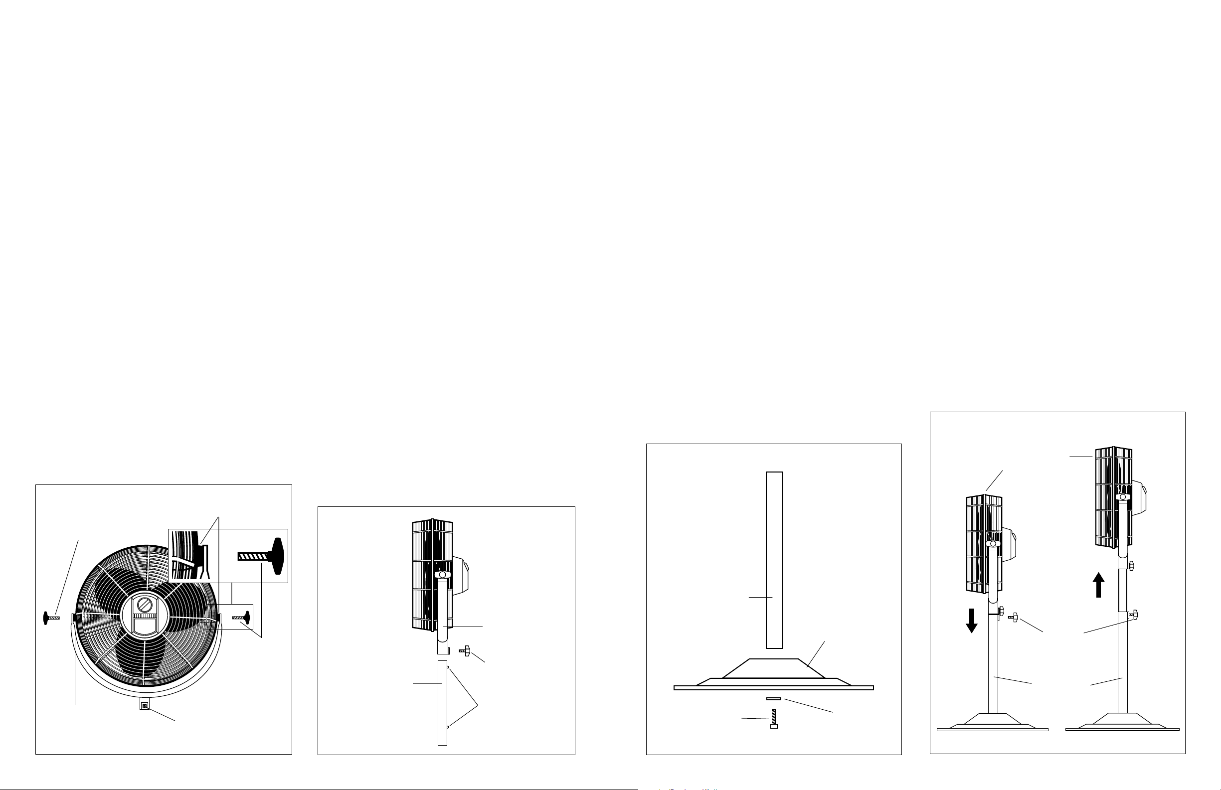
ASSEMBLY
1. Lay Fan Head on flat surface, so the front side is facing
down. Hold Yoke so the side with the nut is facing up.
Loosely attach one Grill Knob and one Rubber Spacer to
the Head Assembly. Attach the other Grill Knob and
Rubber Spacer to the Head Assembly and FIRMLY tighten.
Return to the first Grill Knob and FIRMLY tighten.
NOTE: THE UPPER PIPE HAS 2 BUMPS, ONE AT EACH
END. THE BUMP CLOSER TO THE END OF THE PIPE
INDICATES THE TOP. THIS END FITS INTO THE YOKE.
2. Make sure Bump on Upper Pipe is aligned with
formed section of Yoke. Insert Upper Pipe into Yoke.
To ensure fit is tight, twist Upper Pipe until it is tight inside
of Yoke.
(Figure 2)
NOTE: THE UPPER PIPE SHOULD FIT COMPLETELY
INSIDE OF THE YOKE.
3. Attach Lower Pipe to Base using Bolt and Split
Lockwasher.
(Figure 3)
FIRMLY tighten with supplied
Hex Wrench.
CAUTION: TO AVOID INJURY, MAKE SURE UPPER
PIPE/FAN HEAD IS SUPPORTED WHEN INSERTING
INTO BOTTOM PIPE OR ADJUSTING HEIGHT.
4. Make sure Bump on Upper Pipe is aligned with
formed section of Lower Pipe. Insert Upper Pipe/Fan
Assembly into Lower Pipe and allow it to slide to the
bottom of the Lower Pipe. Screw a Pipe Knob into Lower
Pipe until it loosely touches the Upper Pipe. Raise Upper
Pipe/Fan Assembly to desired height and FIRMLY tighten
Pipe Knob.
Grill Knob (Large)
Perilla de la Rejilla (Grande)
(Figure 4)
Rubber Spacer
Espaciadores de Caucho
(Figure 1)
HERRAMIENTAS NECESARIAS PARA EL
MONTAJE
• Llave Hexagonal (Suministros por Piezas Bolsa)
NOTA: TODO EL MATERIAL EN LAS INSTRUCCIONES PEUDE
SER ENCONTRADO EN LAS BOLSAS DE LAS PIEZAS
SUMINISTRADAS.
MONTAJE
1. Colocar la Cabeza del Ventilador sobre una superficie plana,
de manera que el lado delantero quede hacia abajo. Sostener
la Horquilla de manera que el lado de la tuerca quede hacia
arriba. Fijar flojamente una Perilla de la Rejilla y un Espaciador
de Caucho (Goma) en el Ensamblado de la Cabeza. Fijar la
otra Perilla de la Rejilla y el Espaciador de Caucho (Goma) en
el Ensamblado de la Cabeza y apretar FIRMEMENTE. Regresar
a la primera Perilla de la Rejilla y apretar FIRMEMENTE.
(Figura 1)
NOTA: LA TUBO SUPERIOR TIENE 2 PROTUBERANCIAS,
UNA A CADA LADO. LA PROTUBERANCIA MÁS CERCANA
AL EXTREMO DE LA PIPE INDICA EL RETÉN. ESTE EXTREMO
ENCAJA EN LA HORQUILLA.
2. Asegurarse que la Protuberancia del Tubo Superior quede
alineada con la sección conformada de la Horquilla. Insertar
el Tubo Superior por dentro de la Horquilla. Para garantizar
que el encaje esté apretado, enroscar el Tubo Superior hasta
que quede apretado dentro de la Horquilla.
NOTA: EL TUBO SUPERIOR DEBE ENCAJAR COMPLETAMENTE
DENTRO DE LA HORQUILLA.
3. Fijar la Tubo Inferior a la Base con el Perno y la Arandela de
Seguridad Rayada
suministrada FIRMEMENTE.
ATENCIÓN: PARA EVITAR LESIONES, CERCIORARSE DE
QUE EL TUBO SUPERIOR/CABEZA DEL VENTILADOR ESTÉ
APOYADO CUANDO SE A INSERTADO POR DENTRO DEL
TUBO INFERIOR O CUANDO SE REGULE LA ALTURA.
4. Esté seguro de que la Protuberancia del Tubo Superior
quede alineada con la sección conformada del Tubo
Inferior. Insertar el Tubo Superior/Ensamblado del Ventilador
por dentro del Tubo Inferior y dejarlo que se deslice hasta el fondo
del Tubo Inferior. Enroscar una Perilla del Tubo dentro del Tubo
Inferior hasta que toque flojamente el Tubo Superior. Hacer subir
el Tubo Superior/Ensamblado del Ventilador hasta la altura
deseada y apretar FIRMEMENTE la Perilla del Tubo.
(Figura 3)
Apretar con la Llave Hexagonal
(Figura 2)
(Figura 4)
OPERATING INSTRUCTIONS
1. To Adjust Height: While holding Top Pipe and Fan
Head firmly, loosen Lower Pipe Knob. Adjust Fan up or
down to desired height and FIRMLY retighten Pipe Knob.
2. To Adjust Head Angle: While holding Head firmly,
loosen Grill Knobs on each side of the Yoke (turn
counterclockwise). Tilt Head to desired position and
FIRMLY retighten Grill Knobs.
3. To Operate: Plug cord into a grounded 120V, 60 Hz
outlet. Select desired operating speed with Selector on
back of Fan.
MAINTENANCE
CLEANING: Disconnect from power outlet.
DO NOT IMMERSE FAN IN WATER. Use a soft cloth
moistened with mild soap solution to clean Fan parts.
Avoid the use of gasoline, benzine, thinner, harsh cleaners,
etc. This will result in damage to the material.
Dry all parts thoroughly with a soft cloth before completely
reassembling and reconnecting to power supply.
STORAGE: When not in use, keep unit in a clean dry place.
LUBRICATION: Precision bearings are sealed at the
factory for life and do not require further lubrication.
MODO DE EMPLE
1. Para Regular la Altura: Mientras se sostiene el Tubo Superior
u la Cabeza del Ventilador firmemente, aflojar la Perilla del
Tubo Inferior. Regular el Ventilador hacia arriba o hacia abajo
hasta la altura deseada y volver a apretar la Perilla del Tubo
FIRMEMENTE.
2. Para Ajustar el Ángulo de la Cabeza: Mientras se sostiene
firmemente la Cabeza, aflojar las Perillas de la Rejilla en cada
lado de la Horqueta (haciéndolas girar hacia la izquierda).
Inclinar la Cabeza hasta la posición deseada y volver a apretar
FIRMEMENTE las Perillas de la Rejilla.
3. Para Ponerlo en Marcha: Conecte el cable a un dispositivo
de toma de tierra 120v, 60Hz. Seleccione la velocidad de
funcionamiento deseada con el Selector que esté en la parte
de atrás del Ventilador.
MANTENIMIENT
FIGURE 4• FIGURA 4
LIMPIEZA: Desconectelo de la corriente electrica.
NO SUMERJA EL VENTILADOR EN AGUA. Utilice un trapo
suave mojado con una solucion de jabon ligero para limpiar las
piezas del Ventilador.
Evite el uso de gasolina, bencina, disolvente, limpiadores
corrosivos, etc... que danarian el material.
Seque todas las piezas completamente con un trapo suave antes
de montarlo de nuevo y de volver a conectarlo.
ALMACENAMIENTO: Cuando no lo utilice, mantenga el aparato
en un lugar limpio y seco.
ENGRASE: Los cojinetes de precision son precintados para toda
la vida en la fabrica y no requieren ningun engrase adicional.
Fan Head Assembly
Ensamblado de la
Cabeza del Ventilador
Rubber Spacer
Espaciadores de Caucho
Figure/Figura 1
Rev. A 9/98
Nut
Tuerca
Grill Knob (Large)
Perilla de la Rejilla
(Grande)
Yoke
Horqueta
Pipe Knob (Small)
Upper Pipe
Tubo Superior
Figure/Figura 2
2 2084439
Perilla del Tubo (Pequeña)
Bumps
Protuberancias
Lower Pipe
Tubo Inferior
Base
Base
Bolt
Perno
Figure/Figura 3
Rev. A 9/98 2084439
5/16" Split
Lockwasher
Arandela de
Seguridad
Rayada-5/16"
Figure/Figura 4
3
Pipe Knob
(Small)
Perilla del Tubo
(Pequeña)
Lower Pipe
Tubo Inferior
 Loading...