

LIMITED WARRANTY
SHOULD ACCESSORY PARTS BE NEEDED, CONTACT THE MANUFACTURER FOR IN-WARRANTY REPLACEMENT PARTS. A
COPY OF PROOF-OF-PURCHASE MUST BE INCLUDED ALONG WITH THE TYPE AND STYLE, WHICH IS LOCATED ON THE
BOTTOM OF YOUR APPLIANCE.
This product is warranted for one year from the date of original purchase against defects in workmanship and/or materials. At our option, parts
that prove to be defective will either be repaired or replaced or the whole product will be replaced.
Should electrical or mechanical repair become necessary during the warranty period, send your complete product, postage or freight pre-paid
to the nearest service center. Call the number below for the service station nearest you.
Should a part need replacement, you must give us the type and style of your appliance. You will find this at the bottom of the appliance. In
either case, a copy of your proof of purchase is requested.
This warranty does not apply if the damage occurs because of accident, improper handling or operation, shipping damage, abuse, misuse,
unauthorized repairs made or attempted, or the use of the product for commercial service.
ALL WARRANTIES, EXPRESSED OR IMPLIED, LAST FOR ONE YEAR FROM THE DATE OF ORIGINAL PURCHASE. THIS
WARRANTY DOES NOT COVER LIABILITY FOR INCIDENTAL OR CONSEQUENTIAL DAMAGES FOR ANY CAUSE WHATSOEVER.
Some states do not allow limitations on how long any implied warranty lasts, or the exclusion or limitation of incidental or consequential
damages, so that the above limitations and exclusions may not apply to you. This warranty gives you specific legal rights. You may also have
other rights which vary from state to state.
FOR PARTS:
Check package contents. If parts are missing, or replacement parts required, please call our PARTS DEPARTMENT
TOLL-FREE AT 1-800-966-2028. MONDAY THROUGH FRIDAY, BETWEEN THE HOURS OF 8 AM AND 4 PM EST.
"PLEASE DO NOT RETURN PRODUCT TO PLACE OF PURCHASE." Reference the type and style of product (located
on the underside of the product) when you call.
FOR TECHNICAL ASSISTANCE and SERVICE CENTER LOCATIONS:
For any questions, comments or the location of your nearest service center, PLEASE CALL OUR TOLL-FREE "HOTLINE"
AT 1-800-233-0268. MONDAY THROUGH FRIDAY, BETWEEN THE HOURS OF 8 AM AND 5 PM EST. Please reference
product name and model no. when you call.
Appliance Service Dept. • P.O. Box 569 Franklin, TN 37065-0569 PLEASE DO NOT SEND PRODUCT TO THIS LOCATION!
GARANTIA LIMITADA
SI NECESITA PIEZAS ADICIONALES FAVOR DE COMUNICARSE CON EL FABRICANTE POR LA GARANTIA DEL REMPLAZO DE PIEZAS.
INCLUYA UNA COPIA DE LA PRUEBA DE COMPRA, EL TIPO Y ESTILO DEL VENTILADOR, ESTA INFORMACION PUEDE LOCALIZARLA EN LA
PARTE DE ABAJO DE LA UNIDAD.
ESTE PRODUCTO ESTA GARANTIZADO CONTRA DEFECTOS DE FABRICACIONY/O MATERIALS POR UN AÑO A PARTIR DE LA FECHA DE
COMPRA. A NUESTRA OPCION, PIEZAS QUE SE COMPRUEBEN QUE ESTEN DEFECTUOSAS SERAN REPARADAS. REMPLAZADAS O SE
REMPLAZARA EL PRODUCTO POR COMPLETO.
SI NECESITA REPARACIONES ELECTRICAS O MECANICAS DURANTE EL PERIODO DE GARANTIA, ENVIE LA UNIDAD POR CORREO O FLETE
PAGADO AL CENTRO DE SERVICIO MAS CERCANO, LISTADO EN ESTA TARJETA.
SI SOLAMENTE NECESITA REMPLAZAR UNA PIEZA, TIENE QUE INDICAR EL TIPO Y ESTILO DEL VENTILADOR, ESTA INFORMACION SE
ENCUENTRA EN LA PARTE DE ABAJO DE LA UNIDAD. DE CUALQUIER FORMA, SE SOLICITA UNA COPIA DE LA PRUEBA DE COMPRA.
ESTA GARANTIA NO ES VALIDA SI EL DANO OCURRE DEBIDO A UN ACCIDENTE, MANEJO, INSTALACION, OPERSCION INCORRECTA, DANO
DURANTE EL TRANSPORTE, MALTRATO, USO INDEBIDO, REPARACIONES HECHAS O INTENTADAS NO AUTHORIZADAS, O EL USO DEL
PRODUCTO PARA FINES COMERCIALES. TODAS LAS GARANTIAS EXPRESAS O IMPLICITAS, TIENEN UNA DURACION DE UN ANO A PARTIR
DE LA FECHA DE COMPRA ORIGINAL. ESTA GARANTIA EXPRESAS O IMPLICITAS, TIENEN UNA DURACION DE UN ANO A PARTIR DE LA FECHA
DE COMPRA ORIGINAL. ESTA GARANTIA NO CUBRE RESPONSABILIDADES POR DANOS PORTUITOS O CONSECUENTES POR NINGUNA
CAUSA. DADO QUE ALGUNOS ESTADOS NO PERMITEN NINGUNA LIMITACION EN LA DURACION DE UNA GARANTIA IMPLICADA, O LA
EXCLUSION O RESTRICCION DE DANOS FORTUITOS O CONSECUENTES. LA LIMITACION O EXCLUSION ANTES MENCIONADA PODRIA SER
NO VALIDA. ESTA GARANTIA EXTIENDE AL COMPRADOR ORIGINAL DERECHOS LEGALES ESPECIFICOS Y USTED PODRIA TENER OTROS
DERECHOS, LOS CUALES VARIAN DE UN ESTADO A OTRO.
PARA PIEZAS:
Examine el contenido del empaque. Si faltan piezas, o los repuestos requerir, sírvase llamar al TELÉFONE GRATUITO
DEL DEPARTAMENTO DE REPUESTOS, AL 1-800-966-2028. DE LUNES A VIERNES, DESDE LAS 8 DE LA MAÑANA
A LAS 4 DE LA TARDE, HORA DEL ESTE. "POR FAVOR NO DEVUELVA EL PRODUCTO AL SITIO DONDE LO
COMPRÓ". Cuando llame, refiérasa al tipo y estilo del producto (situados en la base del producto).
PARA OBTENER ASISTENCIA TÉCNICA Y LAS DIRECCIONES DEL CENTRO DE SERVICIO:
Para cualquier pregunta, comentarios o para obtener la dirección de su centro de servicio más cercano, SÍRVASE LLAMAR
A NUESTRO "TELÉFONO DE EMERGENCIA" GRATUITO AL 1-800-233-0268, DE LUNES A VIERNES, DESDE LAS 8 DE
LA MAÑANA A LAS 4 DE LA TARDE, HORA DEL ESTE. Cuando llame, refiérasa al nombre y número de modelo del producto
Innovators in Home Comfort
TM
18" ADJUSTABLE PEDESTAL FAN (Model 2119)
IMPORTANT SAFETY INSTRUCTIONS
READ AND SAVE THESE INSTRUCTIONS
GENERAL SAFETY INSTRUCTIONS
1. Never insert fingers, pencils, or other foreign objects through the grill.
2. Disconnect fan when moving it from one location to another.
3. Be sure that the fan is on a stable surface when operating, to
avoid the chance of it overturning.
4. Disconnect fan when removing grills for cleaning. Reinstall
grills before reconnecting to power supply.
5. WARNING: To reduce the risk of fire, electric shock or personal
injury:
a) Do not use this fan with any solid-state speed control device.
b) Unplug fan before cleaning or servicing.
c) If you disassemble your fan, completely reassemble before
plugging into outlet.
OPERATION
OSCILLATION: Push down Oscillation Knob on Motor Housing
to make Fan Head move from side to side.
TILTING: Fan Head may be tilted up or down.
HEIGHT ADJUSTMENT: While holding Fan Head in place,
carefully loosen Height Adjustment Nut and adjust fan height.
Firmly tighten Nut.
SPEED: Control fan speed with Switch at rear of Motor.
POLARIZED PLUG
This appliance has a polarized plug (one blade is wider than the
other). To reduce the risk of electric shock, this plug is intended to fit
in a polarized outlet only one way. If the plug does not fit fully in the
outlet, reverse the plug. If it still does not fit, contact a qualified
electrician. Do not attempt to defeat this safety feature.
MAINTENANCE
ALWAYS UNPLUG CORD BEFORE CLEANING OR
DISASSEMBLY.
CLEANING: IMPORTANT! DO NOT immerse electrical parts in
water! Disassembled grills and plastic parts may be immersed to
be cleaned with a mild detergent and water. Wipe all other parts
with soft cloth moistened with water and mild detergent only. DRY
ALL PARTS COMPLETELY BEFORE REASSEMBLING AND
RECONNECTING TO POWER SOURCE.
LUBRICATION: Motor is permanently lubricated.
VENTILADOR DE AJUSTE DE 18" PEDESTAL (Modelo 2119)
INSTRUCCIONES IMPORTANTES DE SEGURIDAD
LEA Y GUARDE ESTAS INSTRUCCIONES
INSTRUCCIONES GENERALES DE SEGURIDAD
1. Nunca meta los dedos, lápices u otros objetos estraños a
través de la rejilla.
2. Desconecte el ventilador cuando lo traslade de un lugar otro.
3. Asegúrese que el ventilador esté en una superficie estable
cuando está funcionando, para evitar la posibilidad de volcarse.
4. Desconecte el ventilador cuando quite las rejillas para limpiar.
5. ADVERTENCIA: Para reducir el riesgo de incendio,
electrochoque o lessiones:
a) No use este ventilador con ningún tipo de dispositivo de
control de velocidad electrónico.
b) Desenchufe el ventilador antes de limpiarlo o repararlo.
c) Si usted desarma el ventilador, armelo completamente
antes de reconectar la energia eléctrica.
FUNCIONAMIENTO
OSCILACION: Oprima la perilla de ocsilación en la cubierta del motor
para mover la cabeza del ventilador de lado a lado.
INCLINACION: La cabeza del ventilador se puede inclinar hacia
arriba o hacia abajo.
ADJUSTE DE LA ALTURA: Sujete la cabeza del ventilador en
su lugar, y suelte cuidadosamente la tuerca para ajustar la altrura
del ventilador. Apriete firmenmente la tuerca.
VELOCIDAD: Controle la velocidad del ventilador con el
interruptor ubicado en la parte trasera del motor.
ENCHUFE POLARIZADO
Este aparato tiene el enchufe polarizado (un diente es más ancho
que el otro). Para reducir el riesgo de electrochoque, este
enchufe esta hecho para que entre al toma corriente de una forma
solamente. Si el enchufe no queda totalmente en el toma
corriente, dele vuelva al enchufe. Si aun no queda, contacte a un
eléctricista capacitado. No trate de anular este aspecto de
seguridad.
MANTENIMIENTO
SIEMPRE DESENCHUFE EL CORDON ELECTRICO ANTES
DE LIMPIAR O DESARMER EL VENTILADOR.
LIMPIEZA; ¡IMPORTANTE! NO sumerja los componentes
eléctricos en agua. Las rejillas desarmadas y las piezas de
plástico se pueden sumergir y limpiar con detergente suave y
agua. Limpie todos los demás componentes con un paño suave
humedecido con agua y un detergente suave solamente. SEQUE
TODAS LAS PIEZAS TOTALMENTE ANTES DE VOLVERLO A
ARMAR Y ENCHUFER EL VENTILADOR.
LUBRICACION: El motor está permanentemente lubricado.
Departamento de Servicio para Equipos • P.O. Box 569 Franklin, TN 37065-0569
¡POR FAVOR, NO ENVÍE EL PRODUCTO A ESTA DIRECCIÓN!
New 2/98 2084259
4
New 2/98
1
2084259
PEDESTAL FAN ASSEMBLY AND OPERATING INSTRUCTIONS
READ AND SAVE THESE INSTRUCTIONS
VENTILADOR DE PEDESTAL INSTRUCCIONES PARA EL ARMADO Y
FUNCIONAMIENTO - LEA Y GUARDE ESTAS INSTRUCCIONES
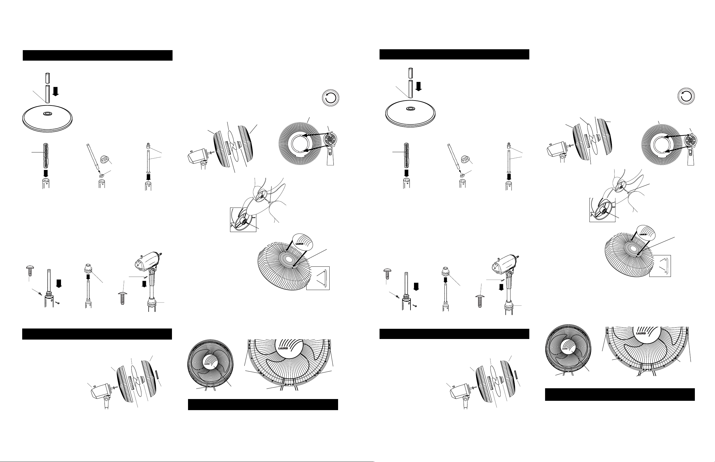
STEP 1: STAND ASSEMBLY
1. With a twisting motion insert the end
of the large diameter Pipe, without
holes, into hole in Round Base.
1
2. LEAVE SPRING IN BAG and drop
into Column.
3. Firmly push plastic Bushing into
end of Extension Pipe that has
raised "bumps".
4. Slide Retainer over Extension Pipe.
Set the Extension Pipe into Column.
2
4
3
5. Fasten Retainer to Column with two Screws.
6. Slide Height Adjustment Nut over Extension Pipe.*
* TO REDUCE THE RISK OF INJURY, DO NOT COMPRESS
SPRING BEFORE MOTOR ASSEMBLY IS INSTALLED.
7. Lower Motor Assembly onto Extension Pipe, turn until Pipe
seats and holes at rear line up. Fasten with Screw as shown.
8. Tighten Height Adjustment Nut.
*
7
5
STEP 2: BLADE & GRILL ASSEMBLY
6
8
1. Tilt Fan Head back. Put Plastic Rear Grill on Motor.
(Figure 5)
Align Triangular "∆" cut in the Plastic Rear Grill with triangular
post on top of front Motor cover. (
Figure 5A
)
Fully seat Plastic Rear Grill and secure with Plastic Nut turning
Clockwise.
Slide Blade onto Motor Shaft. (Align groove on blade hub with pin
on motor shaft.)
(Figure 5B)
To secure Blade, screw Spinner onto Shaft Counter
Clockwise until tight on Blade hub.
PLASTIC REAR GRILL
MOTOR
FIGURE 5A
SLOT
PLASTIC
REAR GRILL
FIGURE 5B
BLADE
PLASTIC NUT
FRONT GRILL
FAN SPINNER
PIN
GROOVE
Install Ornament into
Metal Front Grill. Insert
Tabs into rectangular
Slots. Snap into place.
(Figure 6)
TAB
FIGURE 6
With Fan Head tilted back, align Ornament of Front Grill so it is
horizontal. Insert bottom of Front Grill into Plastic Rear Grill.
Tab at the bottom of Plastic Rear Grill should be between two
Wires of Front Grill. Snap Front into Rear beginning at the top
and working down both sides.
(Figure 7)
PASO 1: CONJUNTO DEL PEDESTAL
1. Insertar, con movimiento rotatorio, el
caño de diámetro grande, sin orificos
dentro del orificio en la base redonda.
1
2
2. DEJAR EL RESORTE EN LA BOLSA
y dejarlo caer dentro de la columna.
3. Empujar firmemente al casquillo de
material plástico en el extremo del
caño de extensión con protuberancias.
4. Deslizar el retón sobre el caño de
extensión. Asentar el caño de
extensión en la columna.
4
3
5. Ajustar el retén a la columna con dos tornillos.
6. Deslizar la tuerca de ajuste de altura sobre el canno do extensión.*
* PARA REDUCIR EL RIESGO DE LESIONES, NO COMPRIMA EL
RESORTE ANTES DE HABER INSTALADO EL CONJUNTO DEL
MOTOR.
7. Bajar el conjunto del motor sobre el caño de extensión, girar hasta qoe
el caño se asiente y los orificios traseros se alineen. Ajustar con tornillo,
como se muestra.
8. Apretar la tuerca de ajuste de la altura.
*
7
5
PASO 2: ENSAMBLE DEL ASPA Y REJILLA
6
8
1. Inclinarla cabeza del ventilador hacia atrás. Coloque la Rejilla Plástica
Trasera en el Motor. (La marca UP indica la parte superior.)
Alinear el corte triagular "∆" de la Rejilla Plástica Trasera con la protuberancia
triangular de la parte superior de la cubierta del Motor.
Asiente la Rejilla y sujetela con la Tuerca de Plástico. Hacia la Derecha.
Deslice la Helice en el Eje del Motor. (Alinear la Ranura Del Cubo de la
TAPA con el Pasador del eje del motor.)
Para asegurar la Paleta, enroscarla hasta que quede apretada
en el Cubo de la Tapa haciéndola girar Hacia la Izuierda.
TAPA DE
HELICE
REJILLA
PLÁSTICA
TRASERA
VENTILADOR
REJILLA
DELANTERA
TUERCA DE
PLÁSTICO
FIGURA 5B
Instale el Adorno. Inserte
las Patitas en las Ranuras
rectangulares. Apriete
para asegurar.
(Figura 6)
(Figura 5B)
REJILLA PLÁSTICA
TRASERA
PASADOR
RANURA DEL CUBO
PATITA
(Figura 5)
5
(Figura 5A)
MOTOR
FIGURA 5A
RANURA
FIGURA 6
Con la Cabeza del Ventilador inclinada hacia atrás y centrada, alinear el
Adorno de tal manera que la divisa quede horizontal. Insertar la parte
inferior de la Rejilla Métalica Delantera dentro de la Rejilla Plástica
Trasera. La proyección de la parte inferior de la Rejilla Plastica Trasera
debe quedar entre dos Alambres de la parte delantera. Cerrar apretando
la parte delantera contra la parte trasera empezando en la parte superior
y continuar cerrando hacia abajo ambos lados.
Innovators in Home Comfort
(Figura 7)
TM
PARTS LIST:
1. PLASTIC REAR GRILL
2. BLADE
3. CONTAINED IN
HARDWARE BAG:
A. Plastic Nut
B. Spinner
C. Ornament
4. FRONT GRILL
5. MOTOR HEAD ASSEMBLY
New 2/98
5
1
2
3A
3B
4
3C
TM
Innovators in Home Comfort
TM
Innovators in Home Comfort
TAB
SNAPS
ORNAMENT
TAB
FIGURE 7
OPERATION
OSCILLATION: Push down oscillation knob on motor housing to
make fan head move from side to side.
TILTING: Fan head may be tilted up or down.
SPEED: Control fan speed with switch at rear of motor.
2
SNAPS
2084259
LISTA DE PIEZAS:
1. REJILLA PLÁSTICA
TRASERA
2. HELICE
3. EN LA BOLSA
5
DE CERRAJERIA:
A. Tuerca de Plástico
B. Tapa
C. Adorno
4. REJIllA DELANTERA
5. CONJUNTO DE LA CAJA DEL MOTOR
New 2/98
1
2
3A
3B
4
3C
TM
Innovators in Home Comfort
PUNTOS
DE
APÉNDICE
ADORNO
CIERRE
APÉNDICE
DE CIERRE
FIGURA 7
FUNCIONAMIENTO
OSCILACION: Empuje la perilla ubicada en la parte superior de la caja del
motor para hacer que la cabeza del Ventilador se mueva de un lugar hacia otro.
INCLINACION: La cabeza del Ventilador se puede inclinar hacia arriba
o hacia abajo.
VELOCIDAD: Controle la velocidad del Ventilador con el cambio de velocidad
en la parte tracera del motor.
3
PUNTOS
2084259
 Loading...