

Lasko 2112 Operating Instruction
LIMITED WARRANTY - NOT VALID IN MEXICO
SHOULD ACCESSOR Y PARTS BE NEEDED , CONTA CT THE MANUFACTURER FOR IN-W ARRANTY REPLACEMENT PAR TS. A COPY OF PROOFOF-PURCHASE MUST BE INCLUDED ALONG WITH THE TYPE AND STYLE, WHICH IS LOCATED ON THE BOTTOM OF YOUR APPLIANCE.
This product is warranted for one year from the date of purchase against defects in workmanship and/or materials. At our option, parts that prove to be
defective will either be repaired or replaced or the whole product will be replaced.
Should electrical or mechanical repair become necessary during the warranty period, please call Customer Ser vice for assistance.
Should a part need replacement, you must give us the type and style of your appliance. You will find this at the bottom of the appliance. In either case, a
copy of your proof-of-purchase is requested.
This warranty does not apply if the damage occurs because of accident, improper handling or operation, shipping damage, abuse, misuse, unauthorized
repairs made or attempted, of the use of the product for commercial service.
ALL WARRANTIES, EXPRESSED OR IMPLIED, LAST FOR ONE YEAR FR OM THE DATE OF ORIGINAL PURCHASE. THIS WARRANTY DOES NOT
COVER LIABILITY FOR INCIDENTAL OR CONSEQUENTIAL DAMAGES FOR ANY CAUSE WHATSOEVER.
Some states do not allow limitations on how long any implied warranty lasts, or the exclusion or limitation of incidental or consequential damages, so that the
above limitations and exclusions may not apply to you. This warranty gives you specific legal rights. You may also have rights which vary from state to state.
CUSTOMER SERVICE:
Toll-Free (800) 233-0268
Our Customer Service team is available to assist you with product questions, service center locations, and replacement parts.
They can be reached Monday through Friday, 8am-5pm Eastern.
Please have your model number available, as well as the type and style (located on the underside of your product).
Please do not return product to place of purchase.
Customer Service Dept., 820 Lincoln Ave., West Chester, PA 19380
(Please do not send product to this location)
.
Email: producthelp@laskoproducts.com
www.laskoproducts.com
12" PEDESTAL FAN
IMPORTANT SAFETY INSTRUCTIONS
READ AND SAVE THESE INSTRUCTIONS
For Replacement Parts please call 1-800-233-0268. For problems or
questions call 1-800-233-0268. PLEASE DO NOT RETURN FAN TO
PLACE OF PURCHASE. Referance the type and style of Fan (located on
bottom) when you call.
This Fan is for residential use only. It is not intended to be
used in commercial or industrial settings.
GENERAL SAFETY INSTRUCTIONS
1. Never insert fingers, pencils, or other foreign objects through the grill.
2. Disconnect Fan when moving it from one location to another.
3. Be sure that the Fan is on a stable surface when operating, to
avoid the chance of it overturning.
4. Disconnect Fan when removing grills for cleaning. Reinstall
grills before reconnecting to power supply.
5. DO NOT use this Fan in a window. Rain may cause an electrical
hazard.
6. WARNING: To reduce the risk of fire, electric shock or personal
injury:
a) Do not use this Fan with any solid-state speed control device.
b) Unplug Fan before cleaning or servicing.
c) If you disassemble your Fan, completely reassemble before
plugging into outlet, according to instructions.
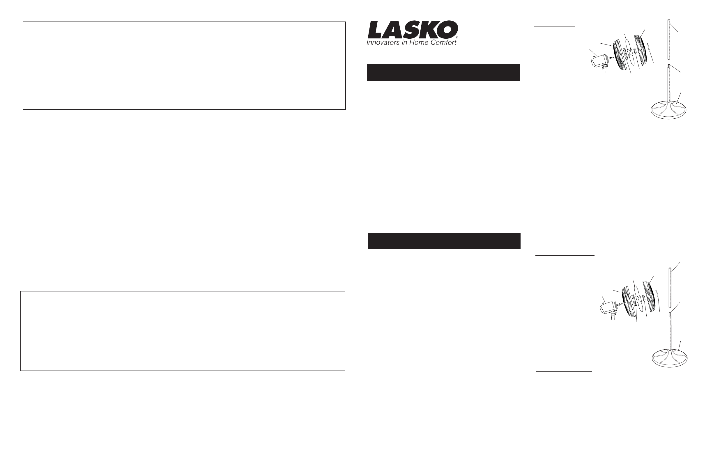
PARTS LIST
1. PLASTIC REAR GRILL
2. BLADE
3. PARTS BAG
A. Plastic Nut
B. Spinner
C. Ornament
4. FRONT GRILL
5. MOTOR HEAD ASSEMBLY
6. BASE
7. TUBE with NOTCH
8. TUBE
with
CONNECTOR installed
1
5
2
4
3C
B
3
3
A
7
8
6
POLARIZED PLUG
This appliance has a polarized plug (one blade is wider than the other).
To reduce the risk of electric shock, this plug is intended to fit in a
polarized outlet only one way. If the plug does not fit fully in the outlet,
reverse the plug. If it still does not fit, contact a qualified electrician. Do
not attempt to defeat this safety feature.
MAINTENANCE
ALWAYS UNPLUG CORD BEFORE CLEANING OR DISASSEMBLY.
CLEANING: IMPORTANT! DO NOT immerse electrical parts in
water! Disassembled grills may be immersed to be cleaned with a mild
detergent and water. Wipe all other parts with soft cloth moistened with
water and mild detergent only. DRY ALL PARTS COMPLETELY
BEFORE REASSEMBLING AND RECONNECTING TO POWER
SOURCE.
LUBRICATION: Motor assembly is permanently lubricated.
EN CASO DE NECESIT AR PIEZAS, COMUNÍQUESE CON EL F ABRICANTE PARA PIEZAS DE REPUESTO AMPARADAS POR LA GARANTÍA. SE DEBE
INCLUIR UNA COPIA DEL RECIBO DE COMPRA CON EL TIPO Y ESTILO DEL CALEFACTOR, UBICADOS EN LA PARTE INFERIOR DEL AP ARATO.
Este producto está garantizado por un año a partir de la fecha de compra contra defectos de fabricación y/o de materiales. A nuestra discreción, las
piezas que resulten defectuosas se reemplazarán o se repararán, o bien se reemplazará el producto entero.
Si se necesita reparación eléctrica o mecánica durante el período de garantía, envíe el producto completo, con porte pagado, al centro de
servicio más cercano. Llame al número que se indica más adelante para encontrar el centro de servicio más cercano.
Si necesita una pieza de repuesto, debe especificar el tipo y el estilo del aparato . Esta información puede encontrarse en la parte inferior del aparato. En
cualquiera de los casos, es necesario que envíe una copia del recibo de compra.
Esta garantía no tiene validez si el daño se debe a un accidente, manejo o uso indebido , daños de transporte, abuso , mal uso, reparaciones o intentos de
reparación no autorizados, o al uso comercial del producto.
TODAS LAS GARANTÍAS, MANIFIESTAS O IMPLÍCITAS, RIGEN DURANTE UN AÑO A PARTIR DE LA FECHA DE COMPRA ORIGINAL. ESTA
GARANTÍA NO CUBRE EN NINGÚN CASO RESPONSABILIDAD POR DAÑOS DIRECTOS O INDIRECTOS POR CAUSA ALGUNA.
En algunos estados no se permiten limitaciones de la duración de una garantía implícita, ni la exclusión o limitación de daños directos o indirectos, por
lo cual las limitaciones y exclusiones anteriores pueden quedar sin vigencia en su caso. Esta garantía le otorga derechos legales específicos. Usted
podría tener otros derechos que varían de un estado a otro.
GARANTIA LIMITADA - NO ES VÁLIDA EN MÉXICO
SERVICIO AL CLIENTE:
Línea Gratuita (800) 233-0268. Correo electrónico: producthelp@laskoproducts.com
Nuestro equipo de Servicio al Cliente está disponible para ayudarle con preguntas sobre productos, ubicación de centros de reparación y
partes de repuesto. Puede ser contactado de lunes a viernes de 8 am a 5 pm Hora del Este. Por favor tenga disponible su número de
modelo, como así también el tipo y el estilo (localizado en la parte inferior de su producto).
Por favor no devuelva el producto al lugar de compra.
Departamento de Servicio al Cliente, 820 Lincoln Ave., West Chester, PA 19380
(Por favor no envíe el producto a este lugar)
www.laskoproducts.com
Rev. A 7/06
20843154
VENTILADOR DE 12" DE PEDESTAL
INSTRUCCIONES IMPORTANTES DE SEGURIDAD
LEA Y GUARDE ESTAS INSTRUCCIONES
Para Repuestos llame al: (800) 233-0268. Si tiene problemas o preguntas,
llame al: (800) 233-0268. POR FAVOR, NO DEVUELA EL VENTILADOR
AL LUGAR DE COMPRA ORIGINAL. Para los pedidos de piezas, haga
referencia al tipo y estilo del ventilador (indicados en el fondo del mismo).
Este Ventilador es para uso residencial únicamente. No está
destinado para uso en ambientes comerciales o industriales.
INSTRUCCIONES GENERALES DE SEGURIDAD
1. Nunca meta los dedos, lápices u otros objetos estraños a
través de la rejilla.
2. Desconecte el Ventilador cuando lo traslade de un lugar otro.
3. Asegúrese que el Ventilador esté en una superficie estable
cuando está funcionando, para evitar la posibilidad de volcarse.
4. Desconecte el Ventilador cuando quite las rejillas para limpiar.
5. NO use este Ventilador en una ventana. La lluvia podría causar
un riesgo eléctrico.
6. ADVERTENCIA: Para reducir el riesgo de incendio,
electrochoque o lessiones:
a) No use este Ventilador con ningún tipo de dispositivo de
control de velocidad electrónico.
b) Desenchufe el Ventilador antes de limpiarlo o repararlo.
c) Si usted desarma el Ventilador, armelo completamente antes
de reconectar la energia eléctrica. Conforme a instrucciónes.
ENCHUFE POLARIZADO
Este aparato tiene el enchufe polarizado (un diente es más ancho
que el otro). Para reducir el riesgo de electrochoque, este enchufe
esta hecho para que entre al toma corriente de una forma solamente.
Si el enchufe no queda totalmente en el toma corriente, dele vuelva
al enchufe. Si aun no queda, contacte a un eléctricista capacitado.
No trate de anular este aspecto de seguridad.
Rev. A 7/06
LISTA DE PIEZAS
1. REJILLA PLÁSTICA TRASERA
2. ASPA
3. EN LA BOLSA DE PIEZAS
A. TUERCA DE PLASTICO
B. TAPA
C. ADORNO
4. REJILLA DELANTERA
5. CONJUNTO DE LA
CAJA DEL MOTOR
6. BASE
7. TUBO CON CORTE
8. TUBO CON
EMPALMADOR INSTALADO
MANTENIMIENTO
SIEMPRE DESCONECTE ANTES DE LIMPIAR O DES
MANTELAR EL VENTILADOR.
LIMPIEZA: ¡IMPORTANTE! NO sumerja las piezas electricas en
agua. Para limpiar rejillas se pueden sumerjir en agua con jabon
suave. Use un paño suave humedecido con una solucion de jabon
suave para limpiar otras partes. SEQUE TODAS LAS PARTES
COMPLETAMENTE ANTES DE ARMAR Y ENCHUFAR EL
VENTILADOR.
LUBRICACION: Conjunto de motor estan lubricados
permanentemente de por vida.
1
7
2
1
5
3A
4
8
3C
B
3
6
2084315
Notched End
BASE
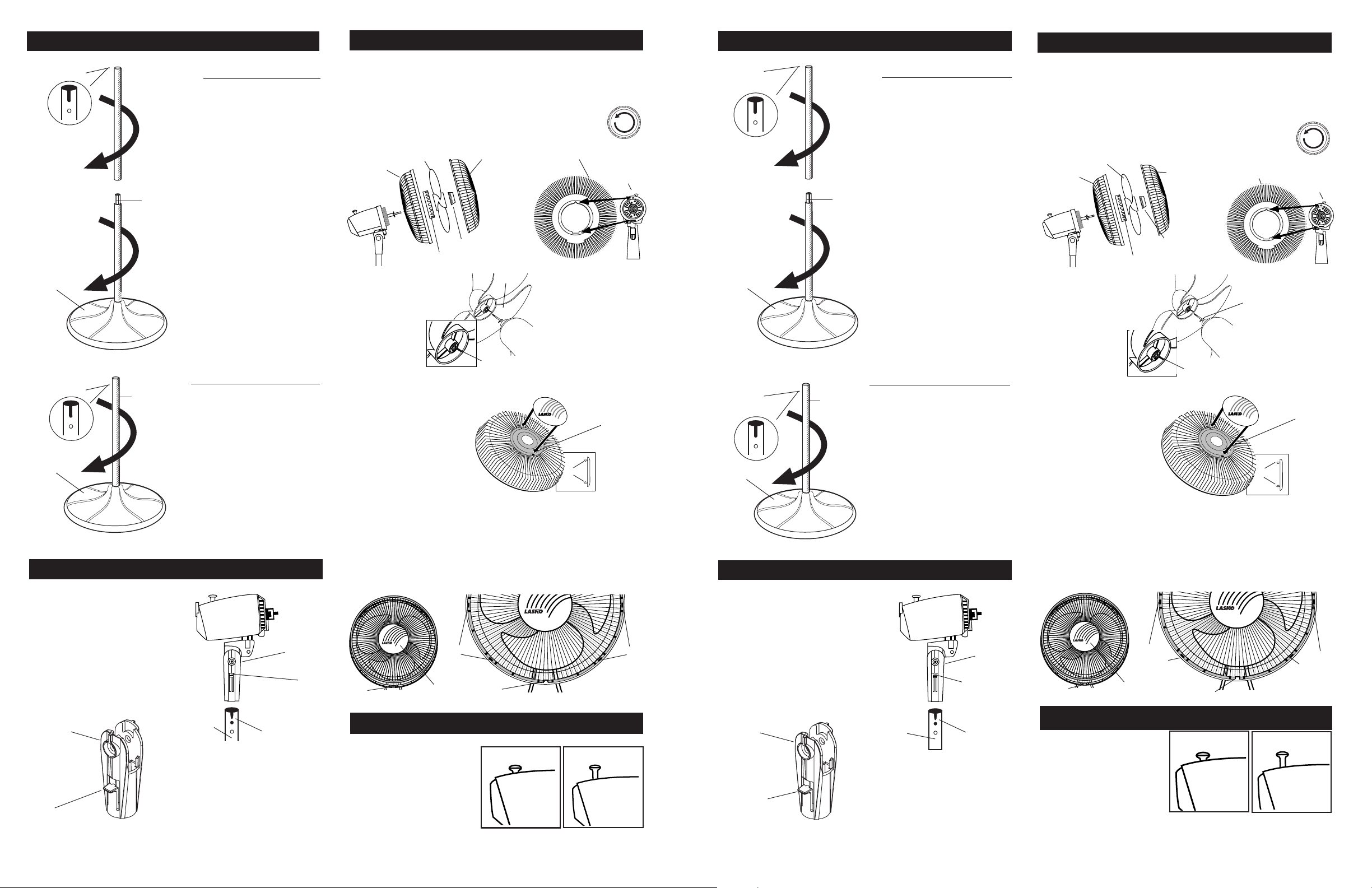
STEP 1: STAND ASSEMBLY
FOR TALL HEIGHT
PLACE BASE FLAT ON FLOOR
1. Push Tube with Connector
into Base leaving connector end
up. Turning Tube while
pushing will assure Tube is
fully seated in Base. (
TUBE
CONNECTOR
with
2. Push Tube
without
onto other Tube ,over connector.
Turning Tube while pushing
will assure Tube is fully seated
on Connector. (
Figure 1
Figure 1
Connector
)
)
STEP 3: BLADE & GRILL ASSEMBLY
3. Tilt Fan Head back. Put Plastic Rear Grill on Motor Assembly.
(Figure 5)
triangular post on top of front Motor Assembly cover.
Fully seat Plastic Rear Grill and secure with Plastic Nut turning
Clockwise.Slide Blade onto Motor Assembly Shaft. (Align
groove on blade hub with pin on motor assembly assembly shaft.)
onto Shaft Counter Clockwise until tight on Blade hub.
PLASTIC
REAR GRILL
FIGURE 5
Align Triangular "∆" cut in the Plastic Rear Grill with
(Figure 5A)
(Figure 5B)
BLADE
PLASTIC NUT
To secure Blade, screw Spinner
FRONT GRILL
FAN SPINNER
PIN
PLASTIC REAR GRILL
FIGURE 5A
MOTOR
ASSEMBLY
PASO 1: ENSAMBLE DEL PIE
Corte en la
punta del tubo
BASE
PARA ALTURA ALTA
COLOQUE LA BASE EN EL PISO
1. Empuje el tubo (con
empalmador) en la base
dejando la punta con corte hacia
arriba. Girar el Tubo al irlo
introduciendo para que
ilegue a lo profundo de la
Base.
(Figura 1)
TUBO CON
EMPLAMADOR
2. Empuje el tubo (sin
empalmador) hacia el tubo con
empalmador. Girar el Tubo al
irlo introduciendo para que
ilegue a lo profundo de la
Emplamador.
(Figura 1)
PASO 3: ENSAMBLE DEL ASPAY REJILLA
3. Inclinarla cabeza del ventilador hacia atrás. Coloque la Rejilla Plástica
Trasera en el Conjunto de Motor. (La marca UP indica la parte superior.)
(Figura 5)
protuberancia triangular de la parte superior de la cubierta del Conjunto de
Motor.
Hacia la Derecha. Deslice la Helice en el Eje del Conjunto de Motor.
(Alinear la Ranura Del Cubo de la TAPA con el Pasador del eje del
conjunto de motor.)
enroscarla hasta que quede apretada en el Cubo de la Tapa
haciéndola girar Hacia la Izuierda.
REJILLA
PLÁSTICA
TRASERA
FIGURA 5
Alinear el corte triagular "∆" de la Rejilla Plástica Trasera con la
(Figura 5A)
Asiente la Rejilla y sujetela con la Tuerca de Plástico.
(Figura 5B)
HELICE
TUERCA DE
PLÁSTICO
Para asegurar la Paleta,
REJILLA
METÁLICA
DELANTERA
TAPA DE
VENTILADOR
REJILLA PLÁSTICA
TRASERA
5
CONJUNTO
DE MOTOR
FIGURA 5A
PASADOR
GROOVE
FIGURE 5B
SLOT
Corte en la
punta del tubo
Notched End
FIGURE 1
TUBE
CONNECTOR
FOR SHORT HEIGHT
without
Install Ornament into
Metal Front Grill. Insert
Tabs into rectangular
BASE
PLACE BASE FLAT ON FLOOR
1. Push Tube
into Base leaving notch end up.
without
Connector
Slots. Snap into place.
(Figure 6)
TAB
BASE
Turning Tube while pushing
will assure Tube is fully seated
in Base. (
Figure 2
)
FIGURE 6
With Fan Head tilted back, align Ornament of Front Grill so it is
FIGURE 2
horizontal. Insert bottom of Front Grill into Plastic Rear Grill. Tab
at the bottom of Plastic Rear Grill should be between two Wires
STEP 2: HEAD ASSEMBLY
of Front Grill. Snap Front into Rear beginning at the top and
working down both sides.
(Figure 7)
NO GRILL CLIPS ARE
PASO 2: CONJUNTO DE LA CABEZA
NEEDED FOR ASSEMBLY.
2. Place Head Assembly with
Collar onto notched end of tube.
Align Snap area on side of Head
Assembly Collar with the Notch
and Catch on Tube. (
Figure 3
Slide the Head Assembly down
onto Tube and press down firmly.
You will feel a definite click when
seated properly and the Head
Assembly will not turn. (
COLLAR
Figure 4
TUBE
CONNECTOR
)
)
without
COLLAR
SNAP
NOTCH
FIGURE 3
TM
Innovators in Home Comfort
TAB
SNAPS
ORNAMENT
OPERATION
OSCILLATION: Push down
oscillation knob on motor
Innovators in Home Comfort
TAB
Down: Oscillate
TM
SNAPS
FIGURE 7
Up: Stationary
2. Ponga el conjunto de la cabeza con
cuello dentro del tubo con corte.
Alinear la parte de Cierre de Resorte del
lado del Cuello del Ensamblado de la
Cabeza, con la Ranura y el Reten del
Tubo. (
Figura 3
Deslizar el Ensamblado de la Cabeza por
el Tubo y presionar firmemente. Se sentirá
un ruidillo definido cuando quede asentado
debidamente y el Ensamblado de la
Cabeza no gire.(
CUELLO
assembly housing to make
fan head move from side to
SNAP
side.
TILTING: Fan head may be
CIERRE DE
RESORTE
tilted up or down.
FIGURE 4
Rev. A 7/06 Rev. A 7/06
SPEED: Control fan speed
with switch at rear of motor assembly.
2
2084315
FIGURA 1
FIGURA 2
)
Figura 4
)
FIGURA 4
PARA ALTURA CORTA
TUBO SIN
EMPALMADOR
COLOQUE LA BASE EN EL PISO
1. Empuje el tubo (sin empalmador)
en la base dejando la punta con
corte hacia arriba. Girar el Tubo al
irlo introduciendo para que ilegue
a lo profundo de la Base. (
CIERRE DE
RESORTE
TUBO SIN
EMPALMADOR
CORTE
FIGURA 3
Figura 2)
CUELLO
RANURA DEL CUBO
FIGURA 5B
Instale el Adorno. Inserte
las Patitas en las Ranuras
rectangulares. Apriete
para asegurar.
(Figura 6)
PATITA
FIGURA 6
Con la Cabeza del Ventilador inclinada hacia atrás y centrada, alinear el
Adorno de tal manera que la divisa quede horizontal. Insertar la parte
inferior de la Rejilla Métalica Delantera dentro de la Rejilla Plástica
Trasera. La proyección de la parte inferior de la Rejilla Plastica Trasera
debe quedar entre dos Alambres de la parte delantera. Cerrar apretando
la parte delantera contra la parte trasera empezando en la parte superior
y continuar cerrando hacia abajo ambos lados.
EL GANCHOS DE LA REJILLA PARA ENSAMBLE.
TM
Innovators in Home Comfort
APÉNDICE
PUNTOS
ADORNO
DE
CIERRE
APÉNDICE
(Figura 7)
TM
Innovators in Home Comfort
NO NECESITO
FIGURA 7
FUNCIONAMIENTO
OSCILACION: Empuje la perilla ubicada en la parte superior de la caja del conjunto
de motor para hacer que la
cabeza del Ventilador se
mueva de un lugar hacia otro.
INCLINACION: La cabeza del
Ventilador se puede inclinar
hacia arriba o hacia abajo.
VELOCIDAD: Controle la velocidad del Ventilador con el cambio de
velocidad en la parte tracera del conjunto de motor.
3
Hacia Adelante:
Oscilar
Hacia Arriba:
Estacionario
RANURA
PUNTOS
DE
CIERRE
2084315
 Loading...