

Page 1
MODELO 1880
MANTENIMIENTO
Para reducir el riesgo de choque eléctrico e incendio, por favor obedezca las siguientes instrucciones.
- Siempre desconecte el cable eléctrico antes de trasladar, reparar o limpiar.
- NUNCA coloque el Ventilador dentro de o cerca de agua.
- Las parrillas desmontadas se pueden sumergir para ser limpiadas con un detergente y agua.enjuga templados
todas las otras partes con tela suave humedecida con agua y detergente templado sólo. SEQUE TODO
DESPIDE COMPLETAMENTE ANTES DE VOLVER A MONTAR. Después que cualquier conservación o
atender a, vuelven a montar completamente la unidad como descrito en este manual de la instrucción antes
de conectar de nuevo a la alimentación.
- NUNCA use ALCOHOL o SOLVENTES tales como gasolina, bencina, disolvente para pinturas u otros
limpiadores duros.
IMPORTANT INSTRUCTIONS -
OPERATING MANUAL
18” REMOTE CONTROL PEDESTAL FAN
MODEL 1880
REPARACIONES: Cualesquiera otras repar aciones, con la excepción del mantenimiento gener al a cargo del usuario, deben
ser realizadas por un representante de servicio autorizado. Llame al 1-800-233-0268, de lunes a viernes, entre las 8:00 a.m. y
las 5:00 p.m. EST para conocer la ubicación de su centro de reparaciones más cercano.
ALMACENAMIENTO: Almacene el Ventilador con estas instrucciones, en la caja or iginal en un lugar fresco y seco.
LUBRICACION: Conjunto de motor estan lubricados permanentemente de por vida.
EN CASO DE NECESIT AR PIEZAS, COMUNÍQUESE CON EL F ABRICANTE PARA PIEZAS DE REPUESTO AMP ARAD AS POR LA GARANTÍA. SE DEBE
INCLUIR UNA COPIA DEL RECIBO DE COMPRA CON EL TIPO Y ESTILO DEL CALEFACTOR, UBICADOS EN LA PARTE INFERIOR DEL APARATO.
Este producto está garantizado por un año a partir de la fecha de compra contra def ectos de f abricación y/o de materiales. A n uestra discreción, las
piezas que resulten defectuosas se reemplazarán o se repararán, o bien se reemplazará el producto entero.
Si se necesita reparación eléctrica o mecánica durante el período de garantía, envíe el producto completo, con porte pagado, al centro de
servicio más cercano. Llame al número que se indica más adelante para encontrar el centro de servicio más cercano.
Si necesita una pieza de repuesto, debe especificar el tipo y el estilo del aparato . Esta información puede encontrarse en la parte inferior del aparato. En
cualquiera de los casos, es necesario que envíe una copia del recibo de compra.
Esta garantía no tiene validez si el daño se debe a un accidente, manejo o uso indebido , daños de transporte, abuso , mal uso, reparaciones o intentos de
reparación no autorizados, o al uso comercial del producto.
TODAS LAS GARANTÍAS, MANIFIESTAS O IMPLÍCITAS, RIGEN DURANTE UN AÑO A PARTIR DE LA FECHA DE COMPRA ORIGINAL. ESTA
GARANTÍA NO CUBRE EN NINGÚN CASO RESPONSABILIDAD POR DAÑOS DIRECTOS O INDIRECTOS POR CAUSA ALGUNA.
En algunos estados no se permiten limitaciones de la duración de una garantía implícita, ni la exclusión o limitación de daños directos o indirectos, por
lo cual las limitaciones y exclusiones anteriores pueden quedar sin vigencia en su caso. Esta garantía le otorga derechos legales específicos. Usted
podría tener otros derechos que varían de un estado a otro.
Línea Gratuita (800) 233-0268. Correo electrónico: [email protected]
Nuestro equipo de Servicio al Cliente está disponible para ayudarle con preguntas sobre productos, ubicación de centros de reparación y
partes de repuesto. Puede ser contactado de lunes a viernes de 8 am a 5 pm Hora del Este. Por favor tenga disponible su número de
modelo, como así también el tipo y el estilo (localizado en la parte inferior de su producto).
GARANTIA LIMITADA - NO ES VÁLIDA EN MÉXICO
SERVICIO AL CLIENTE:
Por favor no devuelva el producto al lugar de compra.
Departamento de Ser vicio al Cliente, 820 Lincoln Ave., West Chester, PA 19380
(Por favor no envíe el producto a este lugar)
www.laskoproducts.com
This Fan is for residential use only.
It is not intended to be used in commercial or industrial settings.
READ AND SAVE THESE INSTRUCTIONS
READ CAREFULLY BEFORE ATTEMPTING TO ASSEMBLE,
INSTALL, OPERATE OR MAINTAIN THE PRODUCT DESCRIBED .
PROTECT YOURSELF AND OTHERS BY OBSERVING ALL SAFETY
INFORMATION. FAILURE TO COMPLY WITH
INSTRUCTIONS COULD RESULT IN PERSONAL INJURY AND/OR
PROPER TY DAMAGE!
KEEP INSTRUCTIONS FOR FUTURE REFERENCE.
SAVE THESE INSTRUCTIONS
Rev. A 7/06
12
2085450
Rev. A 7/06
1
2085450
Page 2
+
+
MODEL 5132
GENERAL SAFETY INFORMATION
When using electrical appliances, basic precautions should always be followed to re-
duce the risk of fire, electrical shock and injury to persons, including the following:
Read all instructions before using this Fan.
1. Make certain the power source conforms to the electrical requirements of the Fan.
2. Make certain that the room is equipped with a working smoke detector.
3. Use this Fan only as described in this manual. An y other use not recommended by the man uf acturer ma y cause fire, electrical shoc k, or
injury to persons.
4. To reduce the risk of personal injury and electric shock, the Fan should not be played with or placed where small children can reach it.
5. Unplug power cord before installing, servicing, or moving the Fan.
DO NOT DEPEND ON THE ON/OFF SWITCH AS THE SOLE MEANS OF DISCONNECTING POWER WHEN SER VICING OR MOVING THE FAN. ALWAYS UNPLUG THE POWER CORD. ALWAYS TURN OFF AND UNPLUG FAN BEFORE LEA VING THE AREA. NEVER LEA VE CHILDREN UNATTENDED WHEN THE F AN IS ON OR PLUGGED IN.
6. This Fan must NOT be used in potentially dangerous locations such as flammable, explosive, chemical-laden or wet atmospheres
where gasoline, paint or flammable liquids are used or stored.
7. DO NOT use Fan in or near a window . Rain may create an electrical hazard.
8. Completely assemble Fan, according to instructions, before connecting to power supply.
This appliance has a polarized plug (one blade is wider than the other). T o reduce the risk of electric shoc k,
this plug is intended to fit in a polarized outlet only one way.
insert. If the plug does not fit fully in the outlet, reverse the plug. If it still does not fit, contact a qualified
electrician. DO NOT attempt to defeat this safety feature.
This plug is a safety feature, to reduce the risk of fire, electric shock and personal injury. DO NOT remove,
replace, repair or tamper with the originally supplied plug. If the Fan does not function properly, it may be
due to the safety device incorporated in this plug. Return to an authorized service center or call 800-2330268, Monda y - Friday , between 8:00 a.m. and 5:00 p.m. EST. If the plug warning label is missing or damaged,
call the toll free number for a replacement label.
9. Where possible, avoid the use of e xtension cords because the extension cord ma y ov erheat and cause a fire . If you m ust use an extension
cord, minimize the risk of overheating by using the shortest cord possible and ensuring that it is UL listed. NEVER use a single extension
cord to operate more than one Fan.
10. NEVER operate any Fan with a damaged cord or plug or after the Fan malfunctions, has been dropped or damaged in any
manner. There are no user serviceable parts. Return Fan to an authorized service facility for examination, electrical or
mechanical adjustment or repair.
11. NEVER insert or allow fingers or foreign objects to enter any ventilation or e xhaust opening as it may cause an electric shock or fire, or
damage the Fan. To reduce the risk of fire, DO NOT block or tamper with the Fan in any manner while it is in operation.
12. Always place the F an on a stab le , flat, le v el surf ace when operating, to a v oid the chance of the Fan overturning. Locate the Power Cord
so the Fan or other objects are not resting on it. DO NOT run P o wer Cord under carpeting. DO NOT cov er Power Cord with throw rugs,
runners or the like. Arrange Power Cord away from room traffic and where it will not be tripped over.
13. This Fan is not intended for use in wet or damp locations. Never locate a Fan where it may fall into a bathtub or other water container.
NEVER use Fan where flammable liquids are used or stored.
14. NEVER use Fan outdoors.
Match wide blade of plug to wide slot. Fully
MODELO 1880
CONTROL REMOTO
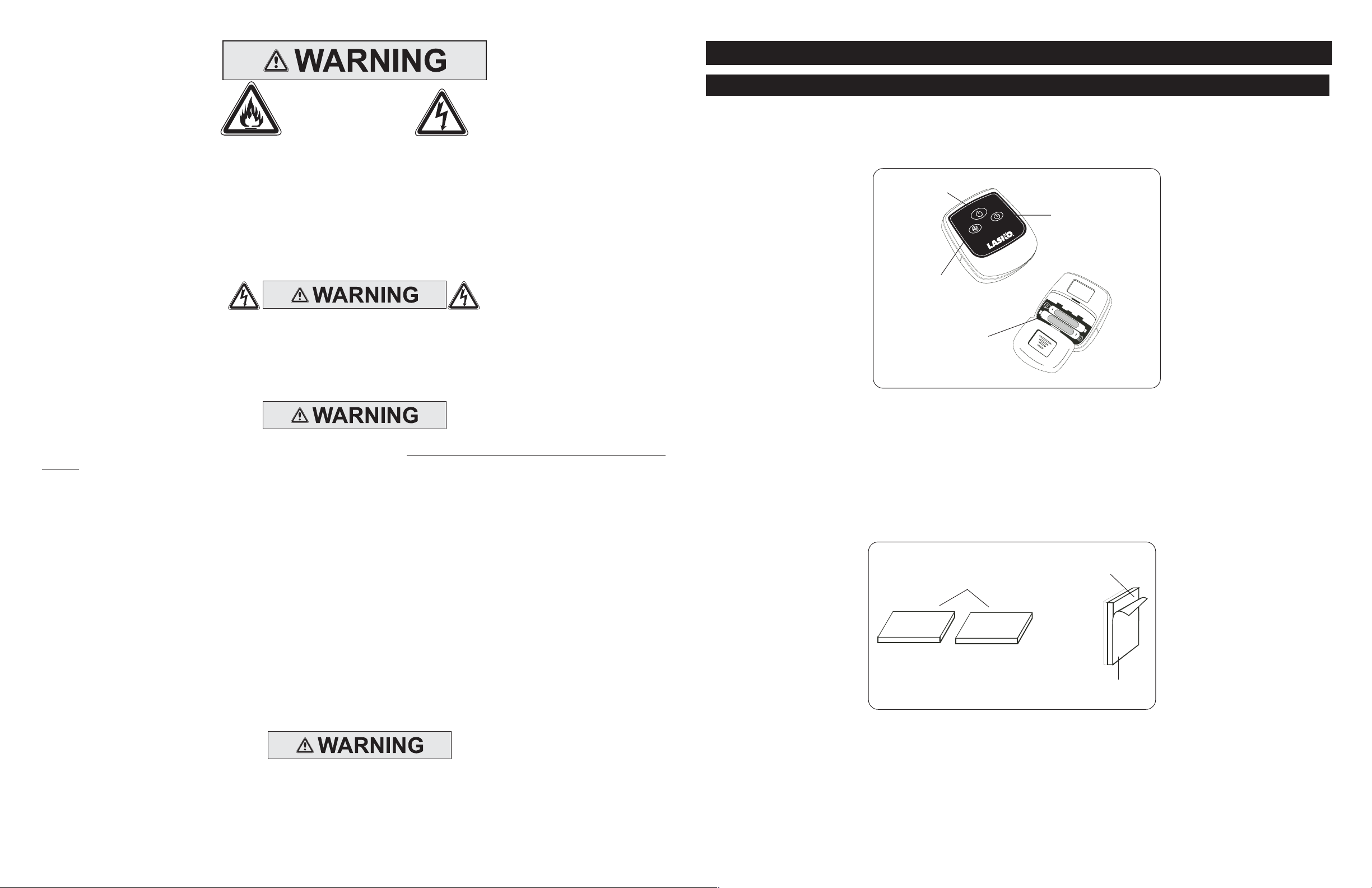
Todas las funciones realizadas con el Control Remoto funcionan idénticamente a los controles manuales.
1. Instale las dos baterías “AAA” suministradas.
2. No mezcle baterías viejas y nuevas. No mezcle baterías alcalinas, estándar (carbono-cinc) o
recargables (níquel-cadmio).
Botón
Alimentación
Botón
Temporizador
M
T
Botón
Velocidad
Baterías
AAA
Figura 14
Si usted pierde su mando a distancia, por fav or Cliente de llamada Serive para ordenar un reaplacement en 1-800 -233-0268,
de lunes a viernes, entre las 8 a.m. y las 5 p.m. (Horario Estándar del Este de los Estados Unidos).
Su ventilador de pedestal con control remoto tiene, además,
cuadrada de Tiras de Fijacíony adhiérala al control remoto. Quite la película protectora del dorso de la otra pieza cuadrada de
Tiras de Fijacíon y adhiérala a su ventilador. Ahora puede guardar su control remoto cuando no lo esté usando.
Tiras De Fijacíon
Figura 15
Tiras de Fijacíon
. Quite la
Adhesivo
Película
Protectora
Película Protectora
del dorso de la pieza
(Figura 15)
REDUCE THE RISK OF FIRE OR ELECTRIC SHOCK - DO NO T USE THIS FAN WITH ANY SOLID ST A TE SPEED
CONTROL DEVICES.
Rev. A 7/06
SAVE THESE INSTRUCTIONS
2
2085450
Rev. A 7/06
11
2085450
Page 3
MODELO 1880
FUNCIONAMIENTO
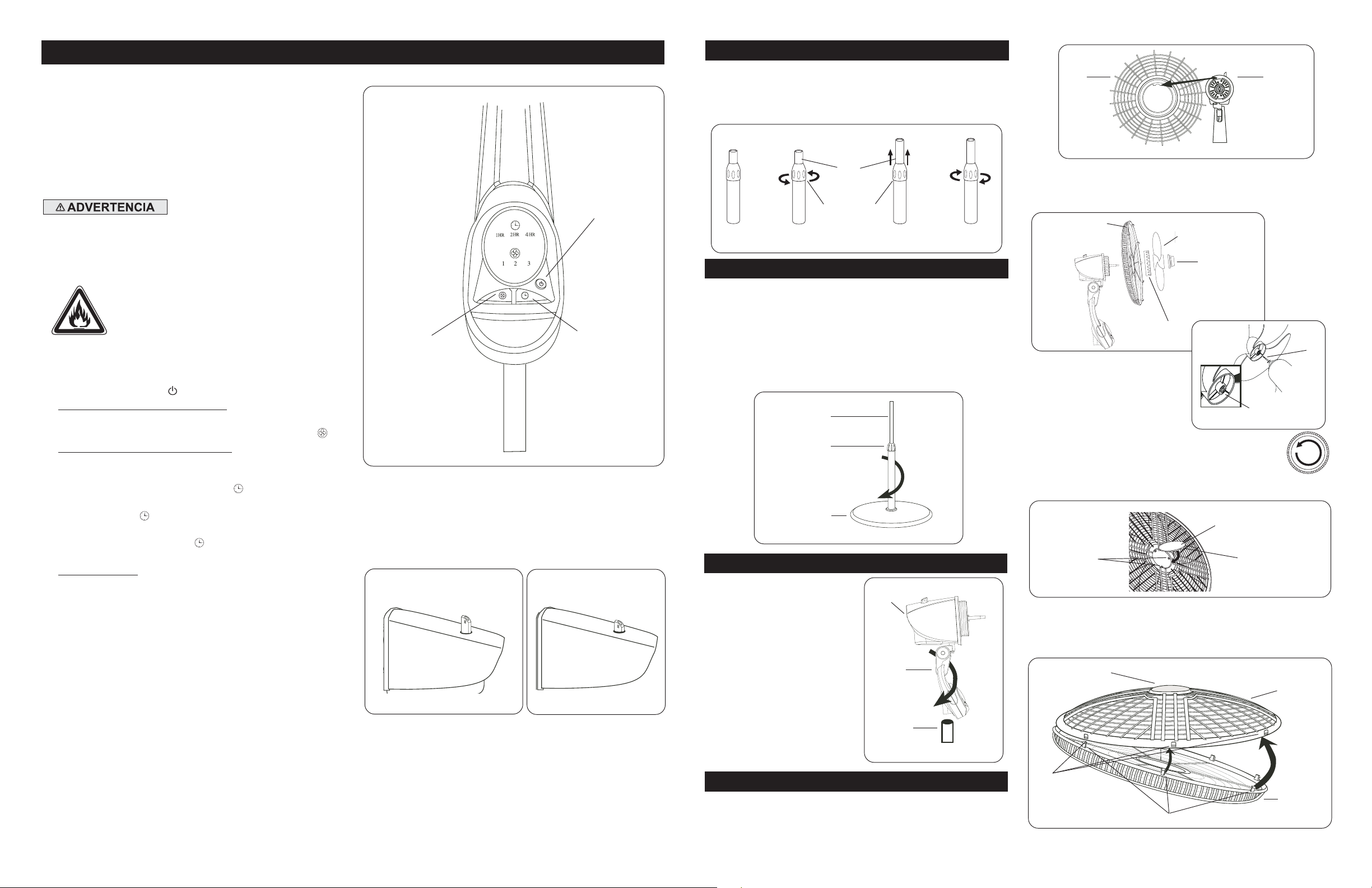
Este Ventilador puede hacerse funcionar mediante los
Controles Manuales ubicados en la parte superior de la
unidad (como se muestra en la
Control Remoto (se muestra en la
1. Cuidadosamente retire el Ventilador de la bolsa plástica y
la caja. Arme la unidad siguiendo estas instrucciones.
2. Coloque el ventilador sobre una superficie firme y nivelada.
3. Conecte el cable eléctrico a un tomacorriente de 120 voltios.
Asegúrese que el enchufe encaje firmemente en el
tomacorriente.
Cuando los enchufes quedan flojos en los
tomacorrientes, pueden deslizarse parcial
o completamente fuera del tomacorriente
con un leve movimiento del cable
adosado. Los tomacorrientes en este
estado podrían sobrecalentarse y
representar un grave peligro de incendio;
si está cubierto por una cor tina o tela, el
riesgo de incendio es aún mayor.
4. Conecte la energía eléctrica a su ventilador pulsando el
Botón Alimentación
( ).
5. VELOCIDAD DEL VENTILADOR: Ahora puede ajustar la
velocidad del ventilador al nivel deseado - 1 (baja), 2
(mediana) ó 3 (alta) - pulsando el
6. FUNCIÓN DE TEMPORIZADOR: Este ventilador está
equipado con un temporizador que le permite a usted
establecer la duración de la operación oprimiendo el
Botón de Función Temporizador
área de control del ventilador, o presionando el
Temporizador
( ) en el control remoto. El temporizador
puede ser programado 1, 2 o 4 horas. Continúe oprimiendo
el
Botón Temporizador
( ) para lograr el tiempo de
programación deseado.
7. OSCILACION: Empuje la perilla ubicada en la parte
superior de la caja del conjunto de motor para hacer
que la cabeza del Ventilador se mueva de un lugar
hacia otro.
(Figuras 12 y 13)
8. Después de apagar el Ventilador, desconecte la unidad del
tomacorriente eléctrico.
Figura 11
Figura 14
Botón Velocidad
) o con el
).
( ).
( ) manualmente en el
Botón
Botón
Velocidad
Figura 11
Hacia Arriba: Estacionario
Figura 12
Botón
Alimentación
Botón Función de
Temporizador
Hacia Adelante: Oscilar
Figura 13
STEP 1: PIPE ASSEMBLY
1. Take pipe assembly out of carton as shown.
2. Loosen
(Figure 2)
3. Raise
4. Tighten
Figure 1
Height Adjustment Nut
Extension Pipe.
Height Adjustment Nut
Figure 2 Figure 4
(Figure 3)
Extension
Pipe
Height
Adjustment
Nut
turning counter clockwise.
turning clockwise.
Figure 3
(Figure 1)
(Figure 4)
STEP 2: STAND ASSEMBLY
PLACE BASE FLAT ON FLOOR
1. With a twisting motion, insert the end of the large diameter
pipe into hole in
will assure pipe is fully seated in
2. For Height Adjustment:
a) Loosen
b)Raise or lower
c) Tighten
Extension Pipe
Adjustment Nut
Figure 5
Base. (Figure 5)
Height Adjustment Nut
Extension Pipe
Height Adjustment Nut
Height
Base
Turning pipe while pushing
Base
.
.
to desired height.
.
STEP 3: HEAD ASSEMBLY
Head
Assembly
1. Place
2. Holding
Head Assembly
Collar
onto
Extension Pipe
(Figure 6)
Extension Pipe
firmly, twist
downward until seated on
Extension Pipe
Head Assembly
.
with
.
Collar
Rear
Grill
Figure 7
3. Fully seat
wise. Slide
Groove
8A)
Figure 8
4. To secure
Clockwise until tight on Blade hub.
5. Install
Snap into place.
Figure 9
6. With fan head in upright position, align
Grill
of the grill and working down, insert
through
Rear Grill
Blade
on blade hub with
Rear Grill
Blade
Ornament
Slots
so it is horizontal and right side up. Starting with the top
Slots
Ornament
and secure with
onto
Motor Assembly Shaft. (Figure 8)
Pin
on motor assembly shaft.
Blade
Plastic
Nut
, screw
into
(Figure 9)
in
Front Grill. (Figure 10)
Spinner
Front Grill
. Insert
Plastic Nut
Fan
Spinner
Figure 8A
onto Shaft Counter
Tabs
Ornament
Snaps
Motor
Assembly
turning Clock-
Groove
into rectangular
Tabs
Ornament
on
Rear Grill
Front Grill
of
Align
(Figure
Pin
Slots
Front
.
Rev. A 7/06
10
2085450
Extension
Pipe
Figure 6
STEP 4: BLADE & GRILL ASSEMBLY
Head Assembly
1. Tilt
(Figure 7)
2. Align tab of Plastic
Motor Assembly
Rev. A 7/06
back. Put
Rear Grill
cover.
Rear Grill
with groove on top of front
on Motor assembly.
Slots
Figure 10
3
Rear Grill
Snaps
2085450
Page 4
MODEL 1880
OPERATION
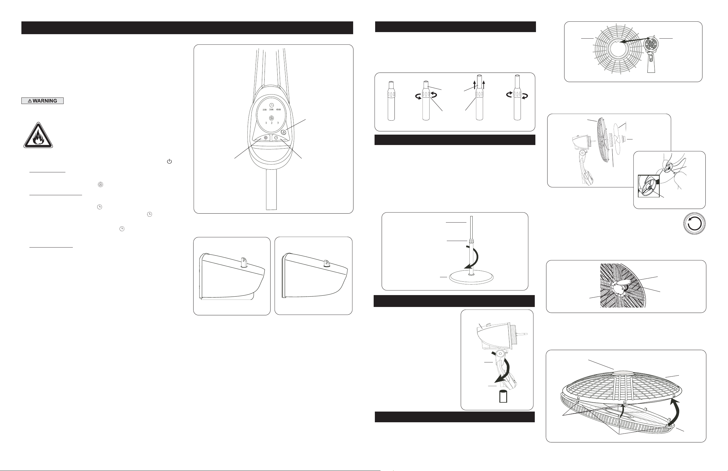
This Fan may be operated by the Manual Controls located
on front of the unit (as shown in
Control (shown in
Figure 14)
1. Carefully remove the Fan from the plastic bag and the
carton. Assemble unit per these instructions.
2. Place the Fan on a firm and level surface.
3. Plug the cord set into a 120 volt outlet.
Be sure that the plug fits tightly into outlet.
When plugs fit loosely into receptacles, they may
slip partially or completely out of the receptacle
with only the slight movement of the attached
cord. Receptacles in this condition ma y overheat
and pose a serious fire hazard; if covered by a
curtain or drape, the fire hazard is even greater.
4. Apply power to the Fan by pushing the
5. FAN SPEED: You may now adjust the fan speed to the
desired level, 1 (Low), 2 (Medium), or 3 (High) by pressing
the
Power/Speed Button
6. TIMER FUNCTION: This fan is equipped with a timer that
allows you to set the length of operation by pressing the
Timer Function Button
of the fan, or by pressing the
mote control. The timer can be set for 1, 2, or 4 hours. Continue pressing the
Timer Button
time setting.
7. OSCILLATION: Push down oscillation knob on motor
assembly housing to make fan head move from side to
side.
(Figures 12 and 13)
8. After turning the Fan off, unplug the unit from the
electrical outlet.
Figure 11
) or by the Remote
.
Power Button
( ).
( ).
( ) manually on the control area
Timer Button
( ) on the re-
( ) to reach the desired
Fan Speed
Button
Figure 11
Up: Stationary
Figure 12
Power Button
Timer Function
Down: Oscillate
Figure 13
Button
PASO 1: ARMADO DE LA TUBERÍA
1. Saque el conjunto de la tubería del cartón como muestra.
2. Desafloje la
contrahorario.
3. Eleve la
4. Apriete la
horario.
Figura 1
Tuerca de Ajuste de Altura
(Figura 2)
Extensión De La Tubería. (Figura 3)
Tuerca de Ajuste de Altura
(Figura 4)
Tubería de
Extension
Tuerca de
Ajuste de
Altura
Figura 2
, girando en sentido
, girando en sentido
(Figura 1)
Figura 4Figura 3
PASO 2: ENSAMBLE DEL PIE
COLOQUE LA BASE EN EL PISO
1. Utilizando un movimiento giratorio, inserte el extremo del tubo de
diámetro grande en el agujero de la
a medida que se lo empuja asegura que el tubo quede plenamente
asentado en la
2. Para ajustar la altura:
a) Afloje la
b) Eleve o baje el
deseada.
c) Apriete la
Tubo de Extensión
Figura 5
Base
.
Tuerca de Ajuste de Altura
Tubo de Extensión
Tuerca de Ajuste de Altura
Tuerca de Ajuste
de Altura
Base
Base. (Figura 5)
.
hasta obtener la altura
.
El girar el tubo
PASO 3: CONJUNTO DE LA CABEZA
Conjunto de
Cabezal
1. Coloque el
con el
Extensión. (Figura 6)
2. Sostenga firmemente el
Extensión
de Cabezal
movimiento giratorio hasta que
quede asentado en el
Extensión
Conjunto de Cabezal
Collar
en el
y empuje el
hacia abajo con un
.
Tubo de
Tubo de
Conjunto
Tubo de
Collar
Tubo de
Extensión
Rejilla
Trasera
Figura 7
3. Asiente la
hacia la Derecha. Deslice la
Motor
Pasador
Parrilla Trasera
Figura 8
4. Para asegurar la
quede apretada en el
girar Hacia la Izuierda.
5.Instale el
en las
(Figura 9)
Figura 9
6. Con el cabezal del v entilador en posición v ertical, alinee el
de la
debido hacia arriba. Empiece en la parte superior de la parrilla y
siga hacia abajo, insertando las
Ranuras
Parrilla Trasera
.
(Figura 8)
del eje del conjunto de motor.
Adorno
Ranuras
Renura
Parrilla Delantera
de la
Adorno
Alinear la
en la
rectangulares. Encájelo a presión en su lugar.
Parrilla Delantera. (Figura 10)
y sujetela con la
Helice
Ranura Del Cubo
Tuerca de
Plastico
Helice
, enroscarla hasta que
Cubo de la Tapa
Parrilla Delantera
de modo que quede horizontal y con el lado
Trabas
en el Eje del
Helice
Tapa de
Ventilador
Figura 8A
de la
(Figura 8A)
haciéndola
. Inserte las
Parrilla T rasera
Conjunto
de Motor
Tuerca de Plástico
Conjunto de
de la tapa con el
Pasador
Ranura del
Cubo
Lengüetas
Adorno
Lengüetas
Adorno
Parrilla
Delantera
en las
Rev. A 7/06
Figura 6
PASO 4: ENSAMBLE DEL ASPAY REJILLA
1. Inclinarla
Trasera
2. Alinear la lengüeta de la
4
2085450
superior de la cubierta delantera del
Rev.A 7/06
Cabeza del Ventilador
en el
Conjunto de Motor. (Figura 7)
Rejilla Trasera
hacia atrás. Coloque la
con la ranura en la parte
Conjunto de Motor
.
Rejilla
Ranuras
Figura 10
9
Trabas
Parrilla
Trasera
2085450
Page 5
+
+
INFORMACIÓN GENERAL DE SEGURIDAD
Al usar artefactos eléctricos, siempre deben tomarse precauciones básicas para reducir
el riesgo de incendio, choque eléctrico y lesiones a personas, incluyendo las siguientes:
Lea todas las instrucciones antes de usar este Ventilador.
1. Asegúrese que la fuente de alimentación coincida con los requerimientos eléctricos del Ventilador.
2. Asegúrese que la habitación esté equipada con un detector de humo en funcionamiento.
3. Use este Ventilador únicamente como se describe en este manual. Cualquier otro uso no recomendado por el fabricante puede causar
incendio, choque eléctrico o lesiones a personas.
4. Para reducir el riesgo de lesiones a personas y choque eléctrico, el Ventilador no debe ser encendido o colocado donde los niños
pequeños puedan alcanzarlo.
5. Desconecte el cable eléctrico antes de instalar, reparar o trasladar el Ventilador.
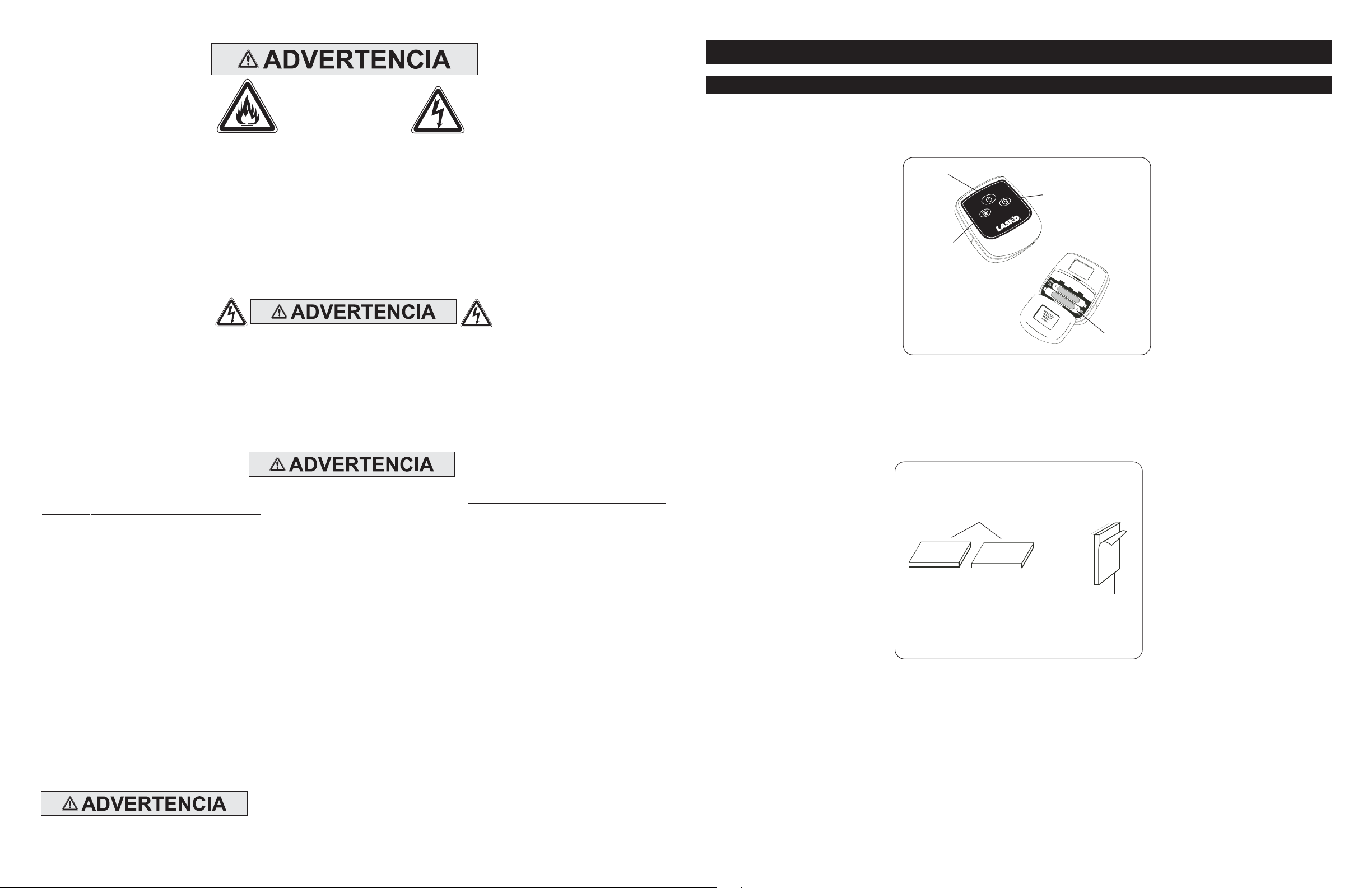
MODEL 1880
REMOTE CONTROL
All the functions performed with the Remote Control work identically to the manual controls.
1. Install the two “AAA” batteries supplied.
2. Do not mix old and new batteries. Do not mix alkaline, standard (carbon-zinc) or rechargeable (nickel-cadmium) batteries.
Power
Button
Speed
Button
MODEL 5132
Timer
Button
M
T
NO DEPENDA DEL INTERRUPTOR DE ENCENDIDO / APAGADO COMO ÚNICO MEDIO DE DESCONECTAR
LA ALIMENT ACIÓN ELÉCTRICA CU ANDO ESTÉ REPARANDO O TRASLADANDO EL VENTILADOR. SIEMPRE
DESCONECTE EL CABLE ELÉCTRICO. SIEMPRE APAGUE Y DESCONECTE EL VENTILADOR ANTES DE
ABANDONAR EL ÁREA. NUNCA DEJE A LOS NIÑOS SIN ATENCIÓN CUANDO EL VENTILADOR ESTÉ
ENCENDIDO O CONECTADO.
6. Este Ventilador NO debe ser usado en lugares potencialmente peligrosos tales como atmósferas inflamables, explosivas , cargadas de
sustancias químicas o húmedas donde se usen o almacenen gasolina, pintura o líquidos inflamables.
7. NOT use el Ventilador dentro de o cerca de una ventana. La lluvia podría crear un riesgo eléctrico.
8. Arme el Ventilador completamente, siguiendo las instrucciones, antes de conectarlo a la fuente de alimentación eléctrica.
Este aparato tiene un enchufe polarizado (una hoja es más ancha que la otra). Para reducir el riesgo de choque eléctrico, este
enchufe está diseñado para encajar en un tomacorriente polarizado en solo un sentido.
con la ranura ancha. Inserte completamente. Si el enchufe no encaja completamente en el tomacorriente, invierta el enchufe. Si
aún así no encaja, comuníquese con un electricista calificado.
NOT intente anular este dispositivo de seguridad.
Este enchufe es un dispositivo de seguridad, para reducir el riesgo de incendio, choque eléctrico y lesiones personales. NO retire,
reemplace, repare o altere el enchufe originalmente pro visto. Si el V entilador no funciona correctamente, puede deberse al dispositivo
de seguridad incorporado en este enchufe. Devuélvalo a un centro de servicios autorizado o llame al 800-233-0268, de lunes a
viernes, entre las 8:00 a.m. y las 5:00 p.m. EST. Si la etiqueta de advertencia del enchufe falta o está dañada, llame a la línea
telefónica gratuita para obtener una nueva etiqueta.
9. Donde sea posible, evite el uso de cables de alargue porque el cable de alargue podría sobrecalentarse y provocar un incendio. Si
debe usar un cable de alargue, minimice el riesgo de sobrecalentamiento usando el cable más corto posible y garantizando que esté
autorizado por UL (Underwriters Laboratories). NUNCA use un solo cable de alargue para hacer funcionar a más de un Ventilador.
10. NUNCA ponga en funcionamiento ningún Ventilador con un cable o enchufe dañado o después que el Ventilador haya tenido f allas de
funcionamiento, haya sido arrojado o dañado de cualquier manera. No hay partes que los usuarios puedan reparar. Devuelva el
Ventilador a una instalación autorizada de servicio para su revisión, ajuste eléctrico o mecánico o reparación.
11. NUNCA inserte o permita que los dedos u objetos extraños ingresen en ninguna abertura de ventilación o escape, ya que esto podría
causar un choque eléctrico o incendio, o dañar el Ventilador. Para reducir el riesgo de incendio, NO bloquee ni altere el Ventilador de
ninguna manera mientras esté en funcionamiento.
12. Siempre coloque el Ventilador en una superficie estable, plana y nivelada mientras esté en funcionamiento, para evitar la posibilidad
de que el Ventilador se caiga. Coloque el Cable Eléctrico de modo tal que el Ventilador u otros objetos no estén apoyados sobre el
mismo. NO coloque el Cable Eléctrico debajo de las alf ombras. NO cubra el Cab le Eléctrico con tapetes, alfombras de hule o similares.
Coloque el Cable Eléctrico lejos del paso de la habitación y donde nadie pueda tropezarse con él.
13. Este Ventilador no está destinado para ser usado en lugares húmedos o mojados. Nunca coloque un Ventilador donde pueda caer
dentro de una tina de baño u otro recipiente de agua. NUNCA use un Ventilador donde se usen o almacenen líquidos inflamables.
14. NUNCA use el Ventilador al aire libre.
DISMINUY A EL RIESGO DE INCENDIO O GOLPES DE ELECTRICIDAD – NO USE ESTE
VENTILADOR CON ARTEF A CTOS DE CONTR OL DE VELOCID AD EN EST ADO SÓLIDO .
Rev. A 7/06
CONSERVE ESTAS INSTRUCCIONES
8
Haga coincidir la hoja ancha del enchufe
2085450
AAA
Figure 14
Batteries
If you lose your remote control, please call Customer Service to order a replacement at 1-800-233-0268, Monday through
Friday, between the hours of 8:00 a.m. and 5:00 p.m. EST.
Your Remote Pedestal Fan has also been provided with
Attachment Strips
. Remove the
Film
from rear of Attachment Strip
and adhere to remote. Remove Film from rear of the other Attachment Strip and adhere to your fan. Now you can store your
remote control when not in use.
Rev. A 7/06
(Figure 15)
Figure 15
Attachment
Strips
Adhesive
Film
5
2085450
Page 6
MODEL 1880
MAINTENANCE
To reduce the risk of electrical shock and fire please observe the following instructions:
- Always unplug the cord before mo ving, servicing or cleaning.
- NEVER place the Fan in or near water.
- Disassembled grills may be immersed to be cleaned with a mild detergent and water.Wipe all other parts with soft cloth
moistened with water and mild detergent only. DRY ALL PARTS COMPLETELY BEFORE REASSEMBLING. After any
maintenance or servicing, completely reassemble unit as described in this instruction manual before reconnecting to
the power supply.
- NEVER use ALCOHOL or SOLVENTS such as gasoline, benzene, paint thinner, or other harsh cleaners.
SERVICING: All other servicing, with the exception of general user-maintenance, should be performed by an authorized
service representative. Call 1-800-233-0268, Monday through Friday, between the hours of 8:00 a.m. and 5:00 p .m. EST for
the location of your nearest service center.
INSTRUCCIONES IMPORTANTES -
MANUAL DE OPERACIÓN
VENTILADOR DE PEDESTAL DE 18 PULGADAS
CON CONTROL REMOTO
MODELO 1880
STORAGE: Store the Fan with these instructions, in the original carton in a cool, dr y place.
LUBRICATION: Motor assembly is permanently lubricated.
LIMITED WARRANTY - NOT VALID IN MEXICO
SHOULD ACCESSOR Y PARTS BE NEEDED, CONTACT THE MANUFACTURER FOR IN-WARRANTY REPLA CEMENT PARTS. A COPY OF PROOFOF-PURCHASE MUST BE INCLUDED ALONG WITH THE TYPE AND STYLE, WHICH IS LOCATED ON THE BOTTOM OF YOUR APPLIANCE.
This product is warranted for one year from the date of purchase against defects in workmanship and/or materials. At our option, parts that prove to be
defective will either be repaired or replaced or the whole product will be replaced.
Should electrical or mechanical repair become necessary during the warranty period, send your complete product, postage or freight pre-paid to the
nearest service center. Call the number below for the service station nearest you.
Should a part need replacement, you must give us the type and style of your appliance. You will find this at the bottom of the appliance. In either case, a
copy of your proof-of-purchase is requested.
This warranty does not apply if the damage occurs because of accident, improper handling or operation, shipping damage, abuse, misuse, unauthorized
repairs made or attempted, of the use of the product for commercial service.
ALL W ARRANTIES, EXPRESSED OR IMPLIED, LAST FOR ONE YEAR FR OM THE DA TE OF ORIGINAL PURCHASE. THIS W ARRANTY DOES NOT
COVER LIABILITY FOR INCIDENTAL OR CONSEQUENTIAL DAMAGES FOR ANY CAUSE WHATSOEVER.
Some states do not allow limitations on how long any implied warranty lasts, or the exclusion or limitation of incidental or consequential damages, so that the
above limitations and exclusions may not apply to you. This warranty gives you specific legal rights. You may also have rights which vary from state to state.
CUSTOMER SERVICE:
Toll-Free (800) 233-0268
Our Customer Service team is available to assist you with product questions, service center locations, and replacement parts. They can
be reached Monday through Friday, 8am-5pm Eastern. Please have your model number available, as well as the type and style (located
on the underside of your product). Please do not return product to place of purchase.
Customer Service Dept., 820 Lincoln Ave., West Chester, PA 19380
(Please do not send product to this location)
.
Email: [email protected]
www.laskoproducts.com
Este Ventilador es sólo para uso residencial.
No está destinado para ser usado en instalaciones comerciales o industriales.
LEA Y GUARDE ESTAS INSTRUCCIONES
LEA CUID ADOSAMENTE LAS INSTRUCCIONES ANTES DE
INTENTAR ARMAR, INSTALAR, USAR O DAR MANTENIMIENTO
AL PRODUCTO DESCRITO .
PROTÉJASE A SÍ MISMO Y A LOS DEMÁS CUMPLIENDO CON
TODA LA INFORMACIÓN DE SEGURIDAD. EL NO SEGUIR LAS
INSTRUCCIONES PODRÍA RESULTAR EN LESIONES
PERSONALES Y/O DAÑOS A LA PROPIEDAD.
CONSERVE LAS INSTRUCCIONES COMO FUTURA REFERENCIA.
CONSERVE ESTAS INSTRUCCIONES
Rev. A 7/06
6
2085450
Rev. A 7/06
7
2085450
 Loading...