

LIMITED WARRANTY
SHOULD ACCESSORY PARTS BE NEEDED, CONTACT THE MANUFACTURER FOR IN-WARRANTY REPLACEMENT PARTS. A
COPY OF PROOF-OF-PURCHASE MUST BE INCLUDED ALONG WITH THE TYPE AND STYLE, WHICH IS LOCATED ON THE
BOTTOM OF YOUR APPLIANCE.
This product is warranted for one year from the date of original purchase against defects in workmanship and/or materials. At our option, parts
that prove to be defective will either be repaired or replaced or the whole product will be replaced.
Should electrical or mechanical repair become necessary during the warranty period, send your complete product, postage or freight pre-paid
to the nearest service center. Call the number below for the service station nearest you.
Should a part need replacement, you must give us the type and style of your appliance. You will find this at the bottom of the appliance. In
either case, a copy of your proof of purchase is requested.
This warranty does not apply if the damage occurs because of accident, improper handling or operation, shipping damage, abuse, misuse,
unauthorized repairs made or attempted, or the use of the product for commercial service.
ALL WARRANTIES, EXPRESSED OR IMPLIED, LAST FOR ONE YEAR FROM THE DATE OF ORIGINAL PURCHASE. THIS
WARRANTY DOES NOT COVER LIABILITY FOR INCIDENTAL OR CONSEQUENTIAL DAMAGES FOR ANY CAUSE WHATSOEVER.
Some states do not allow limitations on how long any implied warranty lasts, or the exclusion or limitation of incidental or consequential
damages, so that the above limitations and exclusions may not apply to you. This warranty gives you specific legal rights. You may also have
other rights which vary from state to state.
FOR PARTS:
For Replacement Parts please call:1-800-966-2028. MONDAY THROUGH FRIDAY, BETWEEN THE HOURS OF 8 AM
AND 4 PM EST. "PLEASE DO NOT RETURN PRODUCT TO PLACE OF PURCHASE." Reference the type and style of
product (located on the underside of the product) when you call.
FOR TECHNICAL ASSISTANCE and SERVICE CENTER LOCATIONS:
For any questions, comments or the location of your nearest service center, PLEASE CALL OUR TOLL-FREE "HOTLINE"
AT 1-800-233-0268. MONDAY THROUGH FRIDAY, BETWEEN THE HOURS OF 8 AM AND 5 PM EST. Please reference
product name and model no. when you call.
Appliance Service Dept. • 300 Confederate Drive Franklin, TN 37065-0569
PLEASE DO NOT SEND PRODUCT TO THIS LOCATION!
Innovators in Home Comfort
TM
18" 4 in 1 PEDESTAL FAN
IMPORTANT SAFETY INSTRUCTIONS
READ AND SAVE THESE INSTRUCTIONS
For Replacement Parts please call 1-800-966-2028. For problems or
questions call 1-(800) 233-0268. PLEASE DO NOT RETURN FAN TO
PLACE OF PURCHASE. Reference the type and style of Fan (located on
bottom) when you call.
This Fan is for residential use only. It is not intended to be used in
commercial or industrial settings.
GENERAL SAFETY INSTRUCTIONS
1. Never insert fingers, pencils, or other foreign objects through the grill.
2. Disconnect Fan when moving it from one location to another.
3. Be sure that the Fan is on a stable surface when operating, to avoid
the chance of it overturning.
4. Disconnect Fan when removing grills for cleaning. Reinstall grills
before reconnecting to power supply.
5. DO NOT use this Fan in a window. Rain may cause an electrical hazard.
6. WARNING: To reduce the risk of fire, electric shock or personal injury:
a) Do not use this Fan with any solid-state speed control device.
b) Unplug Fan before cleaning or servicing.
c) If you disassemble your Fan, completely reassemble before plugging
into outlet, according to instructions.
7
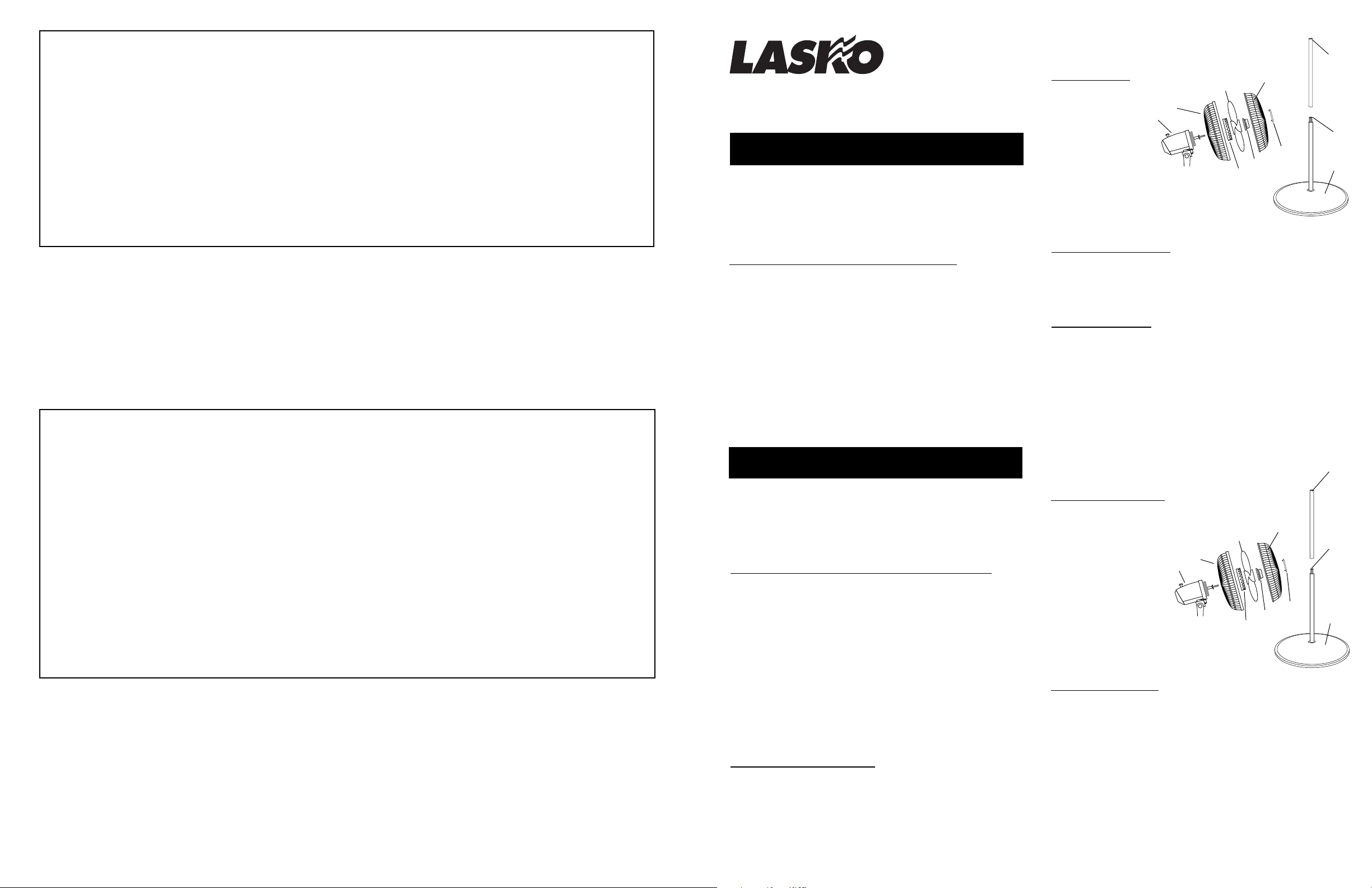
PARTS LIST
1. REAR GRILL
2. BLADE
3. PARTS BAG
A. Plastic Nut
B. Spinner
C. Ornament
4. FRONT GRILL
5. MOTOR HEAD ASSEMBLY
6. BASE
7. TUBE with NOTCH
8. TUBE
with
CONNECTOR installed
5
2
1
4
3C
3B
A
3
POLARIZED PLUG
This appliance has a polarized plug (one blade is wider than the other). To
reduce the risk of electric shock, this plug is intended to fit in a polarized
outlet only one way. If the plug does not fit fully in the outlet, reverse the
plug. If it still does not fit, contact a qualified electrician. Do not attempt
to defeat this safety feature.
MAINTENANCE
ALWAYS UNPLUG CORD BEFORE CLEANING OR DISASSEMBLY.
CLEANING: IMPORTANT! DO NOT immerse electrical parts in water!
Disassembled grills may be immersed to be cleaned with a mild detergent
and water. Wipe all other parts with soft cloth moistened with water and
mild detergent only. DRY ALL PARTS COMPLETELY BEFORE
REASSEMBLING AND RECONNECTING TO POWER SOURCE.
LUBRICATION: Motor is permanently lubricated.
8
6
GARANTIA LIMITADA
SI NECESITA PIEZAS ADICIONALES FAVOR DE COMUNICARSE CON EL FABRICANTE POR LA GARANTIA DEL REMPLAZO DE PIEZAS.
INCLUYA UNA COPIA DE LA PRUEBA DE COMPRA, EL TIPO Y ESTILO DEL VENTILADOR, ESTA INFORMACION PUEDE LOCALIZARLA EN LA
PARTE DE ABAJO DE LA UNIDAD.
ESTE PRODUCTO ESTA GARANTIZADO CONTRA DEFECTOS DE FABRICACIONY/O MATERIALS POR UN AÑO A PARTIR DE LA FECHA DE
COMPRA. A NUESTRA OPCION, PIEZAS QUE SE COMPRUEBEN QUE ESTEN DEFECTUOSAS SERAN REPARADAS. REMPLAZADAS O SE
REMPLAZARA EL PRODUCTO POR COMPLETO.
SI NECESITA REPARACIONES ELECTRICAS O MECANICAS DURANTE EL PERIODO DE GARANTIA, ENVIE LA UNIDAD POR CORREO O FLETE
PAGADO AL CENTRO DE SERVICIO MAS CERCANO, LISTADO EN ESTA TARJETA.
SI SOLAMENTE NECESITA REMPLAZAR UNA PIEZA, TIENE QUE INDICAR EL TIPO Y ESTILO DEL VENTILADOR, ESTA INFORMACION SE
ENCUENTRA EN LA PARTE DE ABAJO DE LA UNIDAD. DE CUALQUIER FORMA, SE SOLICITA UNA COPIA DE LA PRUEBA DE COMPRA.
ESTA GARANTIA NO ES VALIDA SI EL DANO OCURRE DEBIDO A UN ACCIDENTE, MANEJO, INSTALACION, OPERSCION INCORRECTA, DANO
DURANTE EL TRANSPORTE, MALTRATO, USO INDEBIDO, REPARACIONES HECHAS O INTENTADAS NO AUTHORIZADAS, O EL USO DEL
PRODUCTO PARA FINES COMERCIALES.
TODAS LAS GARANTIAS EXPRESAS O IMPLICITAS, TIENEN UNA DURACION DE UN ANO A PARTIR DE LA FECHA DE COMPRA ORIGINAL.
ESTA GARANTIA EXPRESAS O IMPLICITAS, TIENEN UNA DURACION DE UN ANO A PARTIR DE LA FECHA DE COMPRA ORIGINAL. ESTA
GARANTIA NO CUBRE RESPONSABILIDADES POR DANOS PORTUITOS O CONSECUENTES POR NINGUNA CAUSA.
DADO QUE ALGUNOS ESTADOS NO PERMITEN NINGUNA LIMITACION EN LA DURACION DE UNA GARANTIA IMPLICADA, O LA EXCLUSION O
RESTRICCION DE DANOS FORTUITOS O CONSECUENTES. LA LIMITACION O EXCLUSION ANTES MENCIONADA PODRIA SER NO VALIDA.
ESTA GARANTIA EXTIENDE AL COMPRADOR ORIGINAL DERECHOS LEGALES ESPECIFICOS Y USTED PODRIA TENER OTROS DERECHOS,
LOS CUALES VARIAN DE UN ESTADO A OTRO.
PARA PIEZAS:
Para Repuestos Llame al: 1-800-966-2028. DE LUNES A VIERNES, DESDE LAS 8 DE LA MAÑANA A LAS 4 DE LA
TARDE, HORA DEL ESTE. "POR FAVOR NO DEVUELVA EL PRODUCTO AL SITIO DONDE LO COMPRÓ". Cuando
llame, refiérasa al tipo y estilo del producto (situados en la base del producto).
PARA OBTENER ASISTENCIA TÉCNICA Y LAS DIRECCIONES DEL CENTRO DE SERVICIO:
Para cualquier pregunta, comentarios o para obtener la dirección de su centro de servicio más cercano, SÍRVASE
LLAMAR A NUESTRO "TELÉFONO DE EMERGENCIA" GRATUITO AL 1-800-233-0268, DE LUNES A VIERNES,
DESDE LAS 8 DE LA MAÑANA A LAS 4 DE LA TARDE, HORA DEL ESTE. Cuando llame, refiérasa al nombre y número
de modelo del producto
Departamento de Servicio para Equipos • 300 Confederate Drive Franklin, TN 37065-0569
¡POR FAVOR, NO ENVÍE EL PRODUCTO A ESTA DIRECCIÓN!
Rev. A 8/99 (P.O. Box)
20853164
VENTILADOR DE PEDESTAL DE 45,72 CM DE 4 en 1
INSTRUCCIONES IMPORTANTES DE SEGURIDAD
LEA Y GUARDE ESTAS INSTRUCCIONES
Para Repuestos llame al: (800) 966-2028. Si tiene problemas o preguntas,
llame al: (800) 233-0268. POR FAVOR, NO DEVUELA EL VENTILADOR
AL LUGAR DE COMPRA ORIGINAL. Para los pedidos de piezas, haga
referencia al tipo y estilo del ventilador (indicados en el fondo del mismo).
Este Ventilador es para uso residencial únicamente. No está
destinado para uso en ambientes comerciales o industriales.
INSTRUCCIONES GENERALES DE SEGURIDAD
1. Nunca meta los dedos, lápices u otros objetos estraños a través de la
rejilla.
2. Desconecte el Ventilador cuando lo traslade de un lugar otro.
3. Asegúrese que el Ventilador esté en una superficie estable cuando
está funcionando, para evitar la posibilidad de volcarse.
4. Desconecte el Ventilador cuando quite las rejillas para limpiar.
5. NO use este Ventilador en una ventana. La lluvia podría causar un
riesgo eléctrico.
6. ADVERTENCIA: Para reducir el riesgo de incendio, electrochoque o
lessiones:
a) No use este Ventilador con ningún tipo de dispositivo de control de
velocidad electrónico.
b) Desenchufe el Ventilador antes de limpiarlo o repararlo.
c) Si usted desarma el Ventilador, armelo completamente antes de
reconectar la energia eléctrica. Conforme a instrucciónes.
ENCHUFE POLARIZADO
Este aparato tiene el enchufe polarizado (un diente es más ancho que el
otro). Para reducir el riesgo de electrochoque, este enchufe esta hecho
para que entre al toma corriente de una forma solamente. Si el enchufe no
queda totalmente en el toma corriente, dele vuelva al enchufe. Si aun no
queda, contacte a un eléctricista capacitado. No trate de anular este
aspecto de seguridad.
Rev. A 8/99 (P.O. Box)
LISTA DE PIEZAS
1. REJILLA TRASERA
2. ASPA
3. EN LA BOLSA DE PIEZAS
A. TUERCA DE PLASTICO
B. TAPA
C. ADORNO
4. REJILLA DELANTERA
5. CONJUNTO DE LA
CAJA DEL MOTOR
6. BASE
7. TUBO CON CORTE
8. TUBO CON
EMPALMADOR INSTALADO
1
5
MANTENIMIENTO
SIEMPRE DESCONECTE ANTES DE LIMPIAR O DES MANTELAR EL
VENTILADOR.
LIMPIEZA: ¡IMPORTANTE! NO sumerja las piezas electricas en agua.
Para limpiar rejillas se pueden sumerjir en agua con jabon suave. Use un
paño suave humedecido con una solucion de jabon suave para limpiar
otras partes. SEQUE TODAS LAS PARTES COMPLETAMENTE ANTES
DE ARMAR Y ENCHUFAR EL VENTILADOR.
LUBRICACION: Los rodamientos estan lubricados permanentemente de
por vida.
1
2
7
4
8
3C
B
3
A
3
6
2085316
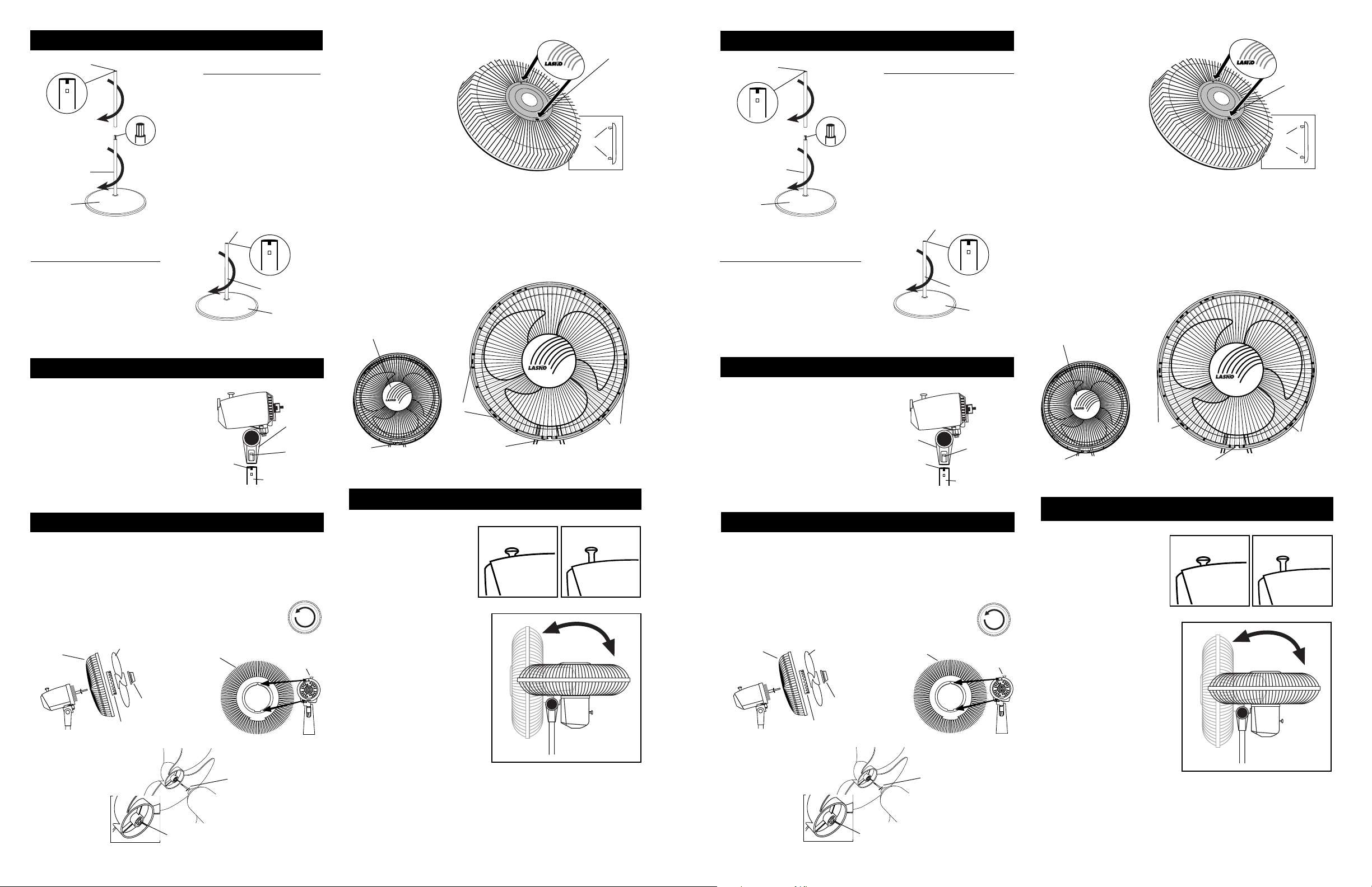
STEP 1: STAND ASSEMBLY
Notched End
PLACE BASE FLAT ON FLOOR
1. Push Tube with Connector
into Base leaving connector end
up. Turning Tube while
pushing will assure Tube is
fully seated in Base. (
TUBE
CONNECTOR
with
BASE
FIGURE 1
FOR SHORT HEIGHT
PLACE BASE FLAT ON FLOOR
1. Push Tube
into Base leaving notch end up.
Turning Tube while pushing will
assure Tube is fully seated in
Base. (
without
Figure 2
Connector
)
2. Push Tube
onto other Tube, over connector.
Turning Tube while pushing will
assure Tube is fully seated on
Connector. (
FOR TALL HEIGHT
Figure 1
without
Figure 1
FIGURE 2
Connector
)
Notched End
TUBE
CONNECTOR
BASE
without
Install Ornament into
Front Grill. Insert Tabs
into rectangular Slots.
Snap into place.
(Figure 5)
)
With Fan Head in upright position, align Ornament of Front Grill so it
is horizontal. Insert bottom of Front Grill into Plastic Rear Grill. Tab at
the bottom of Plastic Rear Grill should fit between spokes of Front
Grill. Snap Front into Rear beginning at the top and working down both
sides.
(Figure 6)
ORNAMENT
NO GRILL CLIPS ARE NEEDED FOR ASSEMBLY.
SLOT
TAB
FIGURE 5
PASO 1: ENSAMBLE DEL PIE
Corte en la
punta del tubo
COLOQUE LA BASE EN EL PISO
1. Empuje el tubo (con empalmador)
en la base dejando la punta con
corte hacia arriba. Girar el Tubo al
irlo introduciendo para que ilegue
a lo profundo de la Base.
TUBO CON
EMPLAMADOR
BASE
FIGURA 1
PARA ALTURA CORTA
COLOQUE LA BASE EN EL PISO
1. Empuje el tubo (sin empalmador)
en la base dejando la punta con
corte hacia arriba. Girar el Tubo al
irlo introduciendo para que ilegue
a lo profundo de la Base. (
Figura 2)
2. Empuje el tubo (sin empalmador)
hacia el tubo con empalmador. Girar
el Tubo al irlo introduciendo para
que ilegue a lo profundo de la
Emplamador.
PARA ALTURA ALTA
(Figura 1)
(Figura 1)
Corte en la
punta del tubo
TUBO SIN
EMPALMADOR
BASE
FIGURA 2
Instale el Adorno. Inserte las
Patitas en las Ranuras
rectangulares. Apriete para
asegurar.
(Figura 5)
RANURA
PATITA
FIGURA 5
Con la Cabeza del Ventilador vertical, alinear el Adorno de tal manera que la
divisa quede horizontal. Insertar la parte inferior de la Rejilla Delantera dentro
de la Rejilla Plástica Trasera. La proyección de la parte inferior de la Rejilla de
Plastica Trasera debe caber entre los Rayos de la Rejilla Delantera. Cerrar
apretando la parte delantera contra la parte trasera empezando en la parte
superior y continuar cerrando hacia abajo ambos lados.
NECESITO EL GANCHOS DE LA REJILLA PARA ENSAMBLE.
ADORNO
(Figura 6)
NO
TM
STEP 2: HEAD ASSEMBLY
2. Place Head Assembly with
Collar onto notched end of tube.
Align Snap area on side of Head
Assembly Collar with the Notch
and Catch on Tube. Slide the Head
Assembly down onto Tube and
press down firmly. You will feel a
definite click when seated properly
and the Head Assembly will not
turn. (
Figure 3
)
NOTCH
FIGURE 3
COLLAR
SNAP
TUBE
without
CONNECTOR
TAB
Innovators in Home Comfort
TM
SNAPS
TAB
Innovators in Home Comfort
SNAPS
FIGURE 6
OPERATION
STEP 3: BLADE & GRILL ASSEMBLY
3. Tilt Fan Head back. Put Plastic Rear Grill on Motor.
Align Triangular "∆" cut in the Plastic Rear Grill with triangular post on
top of front Motor cover. (
Figure 4A
) Fully seat Plastic Rear Grill and
secure with Plastic Nut turning Clockwise.
Slide Blade onto Motor Shaft. (Align groove on blade hub with pin on
motor shaft.)
(Figure 4B)
To secure Blade, screw Spinner onto Shaft Counter
Clockwise until tight on Blade hub.
PLASTIC
REAR
GRILL
BLADE
FAN
SPINNER
PLASTIC NUT
PLASTIC REAR
GRILL
FIGURE 4
PIN
GROOVE
Rev. A 8/99 (P.O. Box) Rev. A 8/99 (P.O. Box) 2085316
FIGURE 4B
(Figure 4)
MOTOR
FIGURE 4A
OSCILLATION: Push down
oscillation knob on motor
Down: Oscillate
Up: Stationary
housing to make fan head
move from side to side.
TILTING: This Fan is equipped
with a multi-angle Fan Head for
Whole-Room Air Circulation.
Follow the steps below to
properly adjust the "tilt angle"
of your Fan.
1. Place one hand on the pole
just under the Fan Neck.
2. Place your other hand on top
of Fan.
3. Gently push or pull the Fan
Head until it is in the desired
position.
NOTE: THE RACHET ASSEMBLY ON THE 18" 4 IN 1 PEDESTAL IS
DESIGNED FOR POSITIVE LOCK POSITIONING. THEREFORE,
WHEN ADJUSTING THE FAN ANGLE A CLICKING SOUND WILL
BE HEARD. THIS IS NORMAL.
SPEED: Control fan speed with switch at rear of motor.
2 2085316
PASO 2: CONJUNTO DE LA CABEZA
2. Ponga el conjunto de la cabeza con
cuello dentro del tubo con corte.
Alinear la parte de Cierre de Resorte
del lado del Cuello del Ensamblado de
la Cabeza, con la Ranura y el Reten
del Tubo. Deslizar el Ensamblado de
la Cabeza por el Tubo y presionar
firmemente. Se sentirá un ruidillo
definido cuando quede asentado
debidamente y el Ensamblado de la
Cabeza no gire.(
Figura 3
)
CUELLO
CORTE
FIGURA 3
CIERRE DE
RESORTE
TUBO SIN
EMPALMADOR
PASO 3: ENSAMBLE DEL ASPAY REJILLA
3. Inclinarla cabeza del ventilador hacia atrás. Coloque la Rejilla Plástica
Trasera en el Motor. (La marca UP indica la parte superior.)
Alinear el corte triagular "∆" de la Rejilla Plástica Trasera con la protuberancia
triangular de la parte superior de la cubierta del Motor.
Asiente la Rejilla y sujetela con la Tuerca de Plástico. Hacia la Derecha.
Deslice la Helice en el Eje del Motor. (Alinear la Ranura Del Cubo de la TAPA
con el Pasador del eje del motor.)
Para asegurar la Paleta, enroscarla hasta que quede apretada en el
Cubo de la Tapa haciéndola girar Hacia la Izuierda.
REJILLA
PLÁSTICA
TRASERA
FIGURA 4
HELICE
TUERCA DE
PLÁSTICO
(Figura 4B)
REJILLA PLÁSTICA
TRASERA
TAPA DE
VENTILADOR
RANURA
DEL CUBO
(Figura 4)
5
(Figura 4A)
FIGURA 4A
PASADOR
FIGURA 4B
MOTOR
TM
Innovators in Home Comfort
TM
Innovators in Home Comfort
PUNTOS
APÉNDICE
DE CIERRE
APÉNDICE
DE CIERRE
FIGURA 6
FUNCIONAMIENTO
OSCILACION: Empuje la
perilla ubicada en la parte
superior de la caja del motor
para hacer que la cabeza del
Ventilador se mueva de un
lugar hacia otro.
INCLINACION: Este Ventilador
está equipado de Cabeza de
Ventilador de ángulo múltiple para
la Circulación del aire por toda
habitación o cuarto.
Siga lo que se indica a continuación
para graduar propiamente el "ángulo
de inclinación" del Ventilador.
1. Ponga una mano sobre el
soporte exactamente por debajo
del Cuello del Ventilador.
2. Ponga la otra mano sobre la
parte superior del Ventilador.
3. Empuje o hale suavemente la
Cabeza del Ventilador hasta que
quede en la posición deseada..
NOTA: EL ENSAMBLE DE LA CREMALLERA EN EL PEDESTAL DE 45,72
CM DE 4 EN 1 ESTA DISENADA PARA QUE TRABE EN CADA POSICIÓN.
ASI QUE CUANDO AJUSTE EL ANGULO DEL VENTILADOR OIRA UN
SONIDO LO CUAL ES NORMAL.
VELOCIDAD: Controle la velocidad del Ventilador con el cambio de velocidad
en la parte tracera del motor.
3
Hacia Adelante:
Oscilar
Hacia Arriba:
Estacionario
PUNTOS
 Loading...