

Page 1

CHIPPER LS 160
model LS 160T
OPERATING INSTRUCTIONS
Orig. version 11.2016
Page 2

Chipper LS 160T
Foreword
Thank you very much that you have just purchased our product, the chipper
LS 160 T. Our company has been engaged in production of equipment for wood residues
crushing and disposal for many years and has gained considerable experiences in this field.
Quality of our small and also powerful machines is proven in 40 countries of Europe and Asia
we export to.
Permanent innovation of the Laski s.r.o. manufacturing assortment was crowned by the Gold
Medal for our complex family of shredding and chipping equipment KDO and LS at the
occasion of the International Trade Fair.
Grand Prix Techagro 1998
Grand Prix Silva Regina 2002
Grand Prix Silva Regina 2008
This manual brings important instructions for users, i.e. instructions for putting the machine
into operation, work safety and operating experiences. You will learn how to carry out
maintenance, repairs and servicing and who is authorised for doing checks and other actions
on the machine.
Your local dealer will give you this manual with instructions for operation and maintenance
while taking this new machine over. Make sure, if you understand everything. If not, do not
hesitate and contact your dealer and ask him for explanation. It is very important for you and
your work safety to understand all instructions given in this manual.
The firm Laski spol. s r.o. does not bear any responsibility for any claims resulting from
disobedience to the instructions given in this manual.
This operation manual includes also work safety instructions in various parts of the text. If
there is any work safety rule or instruction in general description, then this instruction is
indicated with the following symbol:
2
Page 3

Chipper LS 160T
Contents
FOREWORD ........................................................................................................... 2
CONTENTS ............................................................................................................. 3
PRODUCT IDENTIFICATION ........................................................................... 7
WORK SAFETY INSTRUCTIONS ................................ ................................ ..... 8
UTILISATION ......................................................................................................... 8
NOT ALLOWED USE .............................................................................................. 8
GENERALLY .......................................................................................................... 9
MOTOR VEHICLE CONSTRUCTION AND USE REGULATIONS ................................ 15
WORK SAFETY SYMBOLS .................................................................................... 17
RESIDUAL RISKS ................................................................................. 18
TRANSPORT OF PRODUCT/HANDLING ................................................................. 20
PRECAUTIONS IN DESIGN .................................................................................... 20
CONTROLS .......................................................................................................... 23
USE ........................................................................................................................ 25
STORAGE ............................................................................................................. 25
BEFORE PUTTING INTO OPERATION .................................................................... 25
COUPLING TO TRACTORS .................................................................................... 26
CARDAN SHAFT ADJUSTMENT ............................................................................ 28
PUTTING INTO OPERATION .................................................................................. 29
CHIPPING ............................................................................................................ 31
PUTTING OUT OF OPERATION .............................................................................. 34
EMERGENCY SITUATIONS ................................................................................... 34
TECHNICAL DESCRIPTION ........................................................................... 35
Chipping Device ............................................................................................. 35
Frame ............................................................................................................. 36
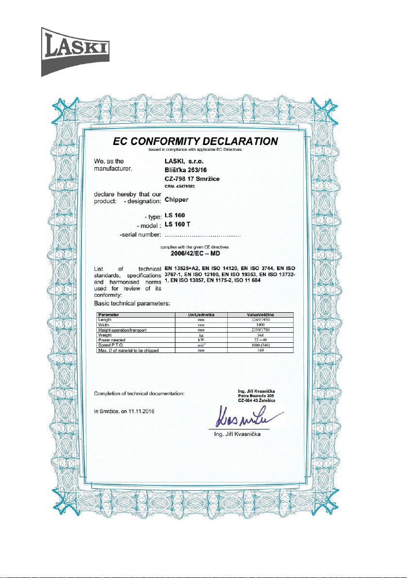
Technical Parameters..................................................................................... 37
MAINTENANCE ................................................................................................. 37
Lubrication ..................................................................................................... 38
Blade Grinding ............................................................................................... 39
Chipping Adjustment ...................................................................................... 40
NOSTRESS System – Speed Regulation ......................................................... 41
........................................................................................................................ 41
3
Page 4

Chipper LS 160T
NOSTRESS SYSTEM PROTECTION AGAINST OVERVOLTAGE ............................... 43
Maintenance Intervals .................................................................................... 47
Checking, Oil Exchange ................................................................................. 48
FAILURES AND TROUBLESHOOTING ................................................................... 48
WASTE DISPOSAL ............................................................................................... 50
WARRANTY ........................................................................................................ 51
SERVICE REPORT ............................................................................................ 52
HYDRAULIC SCHEME ........................................................................................... 53
4
Page 5
Chipper LS 160T
5
Page 6
Chipper LS 160T
6
Page 7
Chipper LS 160T
Type of product:
…………………………………………………….
Serial number of product:
……………………………………………………..
Dealer's address:
……………………………………………………..
Address of authorised service:
……………………………………………………..
Date of delivery:
……………………………………………………..
Warranty expiration date:
……………………………………………………..
Interruption of warranty period:
……………………………………………………..
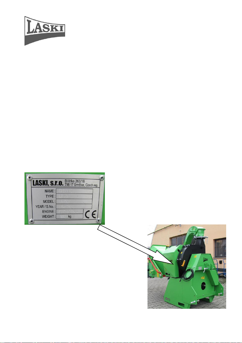
- manufacturer's data
- - product trade name
- - type
- - model
- - year of manufacture and
serial number
- weight of machine
- drive and PTO shaft speed
Product Identification
Our product is identified with its serial number stamped also on the type plate on
its three-point hitch. Upon take-over of the product we recommend you to fill
required data in the following form concerning the given product and your dealer
This type plate includes:
7
Page 8

Chipper LS 160T
Work Safety Instructions
Utilisation
This chipper, being coupled with a tractor three-point hitch, is designed for
disposal of wood waste, twigs, barks, branch-wood and other above-ground
biomass or for manufacture of chips from aforesaid materials and also for disposal
of redundant timber, such as sticks, deals, pickets etc. This chipper is designed for
material loading while the tractor is standing on flat and compact surface. In front
of the loading chute there should be an area with minimum free space of about 5
m.
The chipper can dispose all these materials with diameter up to 160 mm or flat
boards and plates with thickness up to 60 mm .
These wooden pieces must be free of metal, glass and other similar objects. While
working, the chipper must be relatively levelled.
The chipper should be controlled and operated by two attendants who in turns load
materials to be chipped in a loading chute.
Not Allowed Use
The chipper is not allowed to be used for disposal of aforesaid materials with
foreign matters and objects, such as metal, steel binding bands, glass cullet, stony
debris, ceramics etc.
It is not possible to use the chipper in the presence of unauthorised persons who
may stand or move in direction of discharge ducting. At work in residential zones
use the machine in accordance with regulations of the local authorities to avoid
disturbing of local inhabitants (noise level). While chipping, it is not allowed to
enter the area of ejected flying wooden chips.
On hilly terrain its loading chute height should not be lower than 600 mm.
It is not allowed to stand on higher spots around the machine while loading
materials into the chute.
Should some bar materials be loaded, then particular bars should be only up to 3 m
long.
Do not load materials with diameters exceeding 160 mm or wooden boards with
thickness more than 60 mm.
It is strictly forbidden to start the chipper with its cardan shaft damaged.
8
Page 9
Chipper LS 160T
Generally
- This machine is allowed to be operated only by attendants who are over 18 yrs
old, physically and mentally capable and demonstrably instructed with its
operation.
- One of two attendants at least (a tractor driver) should have a respective
driver's license, group "T".
- This machine can be operated by two persons only.
- Training courses for the operating staff should include also practical operation
under supervision of an experienced person or your dealer and with
explanation of necessary work safety instructions.
- Before working learn all functions of individual controls and safety elements
and carry out functional checks before any use. Check especially loading of
materials, functionality and height of the controller frame.
- By pushing the concerned controller in direction of material input the machine
should stop material loading immediately. Any repeated putting machine into
operation is possible only after bringing the frame in its initial position and
pushing the green button on the chute. The controller frame has to be
advanced in front of the hinged loading chute edge so that the attendant
stops the loading rolls at pushing the frame by hand (or leg or belly).
- It is strictly forbidden to change or to set the controller frame so that the STOP
position is hidden under the loading chute edge, see fig.
- To stop loading it is also possible to press the STOP button under the loading
chute.For deactivation turn the STOP button slightly and pull it up. Any other
repeated putting machine into operation is analogical, i.e. after bringing the
frame in its initial position and pushing the green button on the chute.
9
Page 10

Chipper LS 160T
- It is forbidden to tighten the fixing nuts on the safety frame with intend to
increase its resistance against unwished switching off. Required force for
switching control should remain on values preset by the manufacturer, i.e. up
to 80 N in the lower horizontal frame part.
- Any removal of safety elements and guards from the machine and any further
operation without them are strictly forbidden.
- While chipping it is not allowed to enter the area of ejected flying wooden
chips. Every operator of this machine is fully responsible for any injury or
damage caused to the third persons within the operating reach of the machine.
- The end piece of the discharge duct (its upper turnable part) can be set only in
angles, see following figure. Never direct it toward the attendant's place!!
- While working the machine should fully rest on the ground with its frame
bottom part.
- Do not let the machine sink in ditches, trenches or similar undulations. It is
necessary to have flat surface around the machine while working and to keep
recommended loading heights.
- Keep this machine beyond children's and unauthorised person's reach. Avoid
their attendance while chipping.
- When using the chipper without any container or closed bin, keep anybody
beyond the area where chips are being thrown.
- When using the chipper with such a bin, never look inside if the chipper is still
working.
- When leaving the machine take always the switch key out of ignition.
- Every operator of this machine is fully responsible for any injury or damage
caused to the third persons within the operating reach of the machine.
10
Page 11

Chipper LS 160T
- At work in residential zones use the machine in accordance with regulations of
the local authorities to avoid disturbing of local inhabitants (noise, flying
chips).
- Warning !!! Be aware of ejected particles. They have substantial kinetic
energy. If the loaded wooden material contains not allowed parts, such as
metal, sand, glass etc., then such objects can reach a longer distance than
wooden chips. Direct the discharge duct to regulate its ejecting as needed.
- Instructions for use of the cardan shaft operation and the trailing tractor are an
integral part of this manual and should be always respected.
- The cardan shaft guard should be blocked against turning.
- While coupling the chipper to a tractor do not stand between its towing bar
and a tractor. Do not stand behind a towing tractor while backing. Ask other
person to help you with coupling.
- For coupling first attach the cardan shaft to the input shaft of the machine, to
the bottom draw rods and then the top draw rod of the tractor three-point
linkage. Finally attach the cardan shaft to the PTO shaft on the tractor.
While chipping the operator is obliged:
to use only such a chipper which is in optimal operating condition, not
damaged through transport, storage of from previous operation,
It is not allowed to put the machine into operation with its cardan shaft guard
damaged.
to check functions of all controls and safety elements, particularly the
controller frame, before putting the chipper into operation,
to avoid disturbing of other people with noise, exhaust fumes or ejected flying
particles (at windy weather),
to keep traffic rules and local regulations when going or working on or nearby
public roads,
If the discharge duct gets clogged, stop loading immediately. Clean the duct
at standstill only. For cleaning use only suitable hooks or sticks to release
pressed materials. After repeated putting the chipper into operation let the
machine run idle in the chipping mode for a while to empty the whole
discharge ducting and the chipping wheel space. If proper cleaning is required
then take always the switch key out of ignition before removing hoods and
block the tractor against unwilling motion.
While working, never lean over the loading chute and never push wooden
materials with your hand or foot only. While loading short materials, throw
11
Page 12

Chipper LS 160T
them in the chute and push them forward between the loading rolls by means
of a wooden stick or a board, more than 160 cm long, to push materials
between the loading rolls.
Should the pressing stick be indrawn between the roles, do not try to pull it out
by hand - accident risk! Use always a new stick and go on working.
While working wear always personal protective equipment - protecting shield
or goggles, protective gloves, working shoes and working cloth properly
buttoned. Avoid wearing free parts, such as ties, scarves and shawls, belts etc.
In case of longer hairs use always a proper head piece. Otherwise, such a
person is not allowed to operate this machine.
While working, wear always personal protective aids - protecting shield or
goggles, protective gloves, working shoes and working cloth properly
buttoned. Avoid wearing free parts, such as ties, scarves and shawls, belts etc.
In case of longer hairs use always a proper head piece. Otherwise, such a
person is not allowed to operate this machine.
In case of two attendants it is necessary to make simple signals clear before
working and to appoint one who will manage the work. Both attendants must
be properly trained in attendance and turning the chipper off in emergency
cases.
- Keep traffic lights and work safety symbols in proper order.
- Check materials to be loaded and remove all undesirable objects. If you see
such particles in ejected chips, stop working immediately.
- Never load materials with parts of metal, glass and other similar objects (metal
wires, nails etc.).
- This manual describes problems and faults which could occur at work and
which may be remedied by an instructed person. In case of other problems and
faults do not hesitate and contact the manufacturer. He is always ready to help
you.
- Never do any technical changes or any actions which are neither given in this
manual nor allowed by the manufacturer. The machine, not correctly installed
or adjusted, may run without problems now but in the future it could damage
any of important parts. Pay regular attention to all joints and bolts. Keep them
properly tightened.
- Do not put any objects or tools on the machine.
- The manufacturer does not bear responsibility for any damages or injures
caused to the third persons or to other equipment resulted from disobedience
to instructions given in this manual.
- When handing the machine over to another person make sure if all controls,
guards and other safety elements are complete and fully functional.
12
Page 13

Chipper LS 160T
- Never remove guards and other safety elements. They serve for your safety.
- Keep the given intervals for checks of bolted joints.
- Always after work clean all parts of the machine properly. Pay your attention
especially to any oil spots or fuel leakage. Clean any oily spots.
- Some parts of the machine can be hot while in operation. Avoid any settling of
flammable chipped materials on such parts or close to the hydraulic oil tank.
Stop working if such deposits exceed 1 mm.
- Any servicing can be done only if the machine was put out of operation, its
battery was disconnected and the cardan shaft was uncoupled. If the chipper is
still coupled to the three-point hitch, block the tractor (wheels) against
unwanted motion.
- Do not use petrol as a cleaning agent.
- Keep open fire away while filling the tank.
- Keep the machine beyond reach of open fire.
- Some parts of the machine run warm, such as hydraulic elements, belts and
pulleys. Do not touch them when the engine is still running or having been just
stopped.
- Do not let the engine running in high speed unreasonably.
- Do not start the machine in confined or ill-ventilated spaces.
- Combustion gases outgoing from a tractor are toxic!
- Do not use the machine under conditions of low visibility, especially at foggy
weather on public roads.
- Do not use the machine without prior reading this manual.
- Do not carry out any repairs that are specified for authorised services only.
- Do not carry out any repair where its
solution exceeds your experiences.
- It is strictly forbidden to work with the
chipping device damaged (out-ofbalance, vibrations while running).
- While servicing the chipping device, or in
the vicinity thereof, it should be always
blocked against unwilling motion (with
its safety pin inserted).
- Do not let the engine running in high
speed unreasonably.
- Do not start the machine in confined or
ill-ventilated spaces.
- Combustion gases outgoing from a tractor
are toxic!
13
Page 14

Chipper LS 160T
- Do not use the machine under conditions of low visibility, especially at foggy
weather on public roads.
- Do not use the machine without prior reading this manual.
- Do not carry out any repairs that are specified for authorised services only.
- Do not carry out any repair where its solution exceeds your experiences.
- It is strictly forbidden to work with the chipping device damaged (out-of-
balance, vibrations while running).
- While servicing the chipping device, or in the vicinity thereof, it should be
always blocked against unwilling motion (with its safety pin inserted).
-
Before transport on public roads:
At public road transport this machine must be lifted up in its transport
position, see instructions in this manual. First set also the machine in its
transport position, i.e. its loading chute and discharge duct folded down and
mechanically blocked against motion. Its side lights must be visible, not
covered, see fig.
Couple the chipper to a towing vehicle properly and check proper pin
coupling.
Before going on public roads, check up proper coupling and all locks in the
three-point hitch on the tractor.
Plug the machine lights in the tractor socket in rear and check up functions of
all lights.
If necessary, remove all mud, especially from tires, before coming to a public
road.
14
Page 15
Chipper LS 160T
Motor Vehicle Construction and Use Regulations
1. This machine is allowed to be coupled to a tractor provided that actual weight
of the tractor in such an attachment does not exceed its maximum permissible
value and its actual front axle load does not fall under 20% of its gross weight.
2. At public road transport the machine rear must be completed with a portable
set of rear lamps and reflector glasses supplied by the manufacturer.
3. Under conditions of very low visibility any public road transport is not
allowed.
4. Any public road transport without this portable set of rear lamps and reflector
glasses is not allowed – these lamps must always be turned on.
5. This portable set should comprise:
- 2 plates with red-white hatching with reflecting surface
- 2 rear combined lamps with side, stop and direction indicator lights
- 2 rear triangular red reflector glasses
- 1 warning triangle for marking of slow-moving vehicles
Should the tractor speed be higher than 40 km/h, then the warning triangle for
slow-moving vehicles is unnecessary.
15
Page 16

Chipper LS 160T
6. The distance between the outer edge of lamps and reflector glasses in the
portable set and the contour line of the vehicle should not exceed 400 mm.
7. At public road transport this machine must be lifted up in its transport
position, see instructions in this manual.
8. The transport position means that the machine is lifted up; clearance height
under its bottom should be approximately 300 – 400 mm; the PTO drive is
turned off; the turnable discharge duct is folded down and mechanically
blocked; the hinged part of the loading chute is lifted up and mechanically
blocked; all the portable lamps are plugged in the tractor 7-pin socket.
9. While working on public roads, the amber light on the tractor cab must be
turned on.
10. The max. permissible speed of the machine for transport on public roads is not
explicitly specified – a valid value, see the max. permissible speed as specified
for the given tractor.
11. Should the max. speed sign on the tractor be covered by the coupled machine,
then it should be attached to the left plate on the machine rear.
12. Always before coming to a public road it is necessary to remove all mud,
especially from the tractor tires and accumulated sediments from the machine.
13. At public road transport the driver must keep the utmost diligence due to the
fact that the rear part of the coupled machine swings out while manoeuvring.
14. At public road transport the tractor driver must keep also all local regulations
valid for public roads.
16
Page 17
Chipper LS 160T
1 2 3 4 5
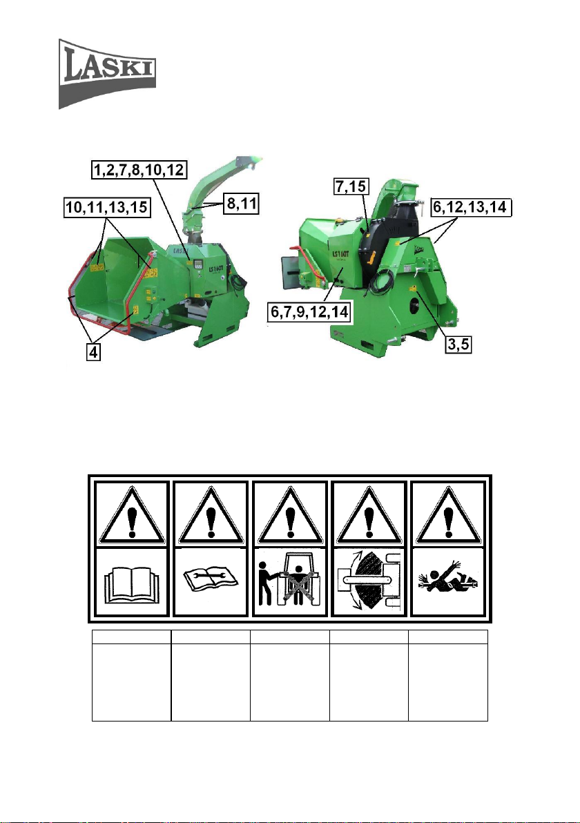
Read this operating
manual before use.
Always follow the
manual while
maintaining,
servicing or
repairing the
machine and take
always the switch
key out of ignition.
Do not stand
between tractor and
equipment while
coupling.
Warning! It swings
out while turning.
Warning! Rotating
parts - accident risk.
Work Safety Symbols
This article introduces work safety symbols (pictographs) used on this machine.
Under the given pos. number there is their location on the machine. These work
safety symbols warn the operator against risks connected with the machine use.
Your respect to the symbol meanings is a precondition for your work safety.
17
Page 18

Chipper LS 160T
6 7 8 9 10
Warning! Hot parts.
Warning! Turning
part is running out.
Warning! Ejected
objects hazard. Keep
away.
Warning! Close all
guards before
starting the machine.
Wear personal
protective
equipment.
11
12
13
14
15
Keep safety distance.
Warning! Risk of
high-pressure liquid
leakage
Warning! Rotating
rolls. Pull-in hazard.
Warning! Hazard of
extremity injury by
rotating part
Warning! Accident
risk.
The user is obliged to keep all the work safety symbols legible, clear and
undamaged. In case of any damage or illegibility ask your local dealer or
an authorised service for a new relevant pictograph.
Residual Risks
OIL PRODUCTS
Hydraulic oil can be injurious to the skin - wash it off as soon as
possible. If taken internally, seek immediate medical attention. Refer to your local
fuel supplier for the MSDS sheet.
18
Page 19

Chipper LS 160T
Store hydraulic oil only in approved containers, in well ventilated, unoccupied
buildings and away from naked flames.
EXHAUST FUMES
Engine exhaust gases contain poisonous carbon monoxide. Carbon monoxide is
odourless, colourless and can cause death if inhaled. Avoid inhaling exhaust fumes
and let never run the tractor engine in a closed building or confined area with
insufficient ventilation.
HOT PARTS
Some machine components (rotating parts, metal parts of hydraulics, hydromotor
etc.) can get extremely hot from operation. To prevent severe burns, do not touch
these areas while the machine is still running - or immediately after it is turned off.
ELECTRICAL SHOCKS
Never touch electrical wires or components while the machine is still running they can be sources of electrical shocks.
ROTATING CHIPPING WHEEL
When the drive is turned off, the chipping wheel could continue to rotate for a
short while. Its teeth are sharp and could cause damage or injury even while not in
motion.
PERSONAL SAFETY
The following personal protective equipment (PPE) must be worn by the person
operating this machine and also all personnel within a 20 metre radius of the
machine:
- forestry safety helmet as to EN 397 fitted with a visor as to EN 166
- heavy duty gloves as to EN 388
- full ear protection as to EN 352-3
- close fitting heavy-duty fully protecting clothing
- steel toe protection boots as to EN ISO 20346
- dust mask if working under dusty conditions.
NOISE
The operating noise level depends on the given tractor type. Before putting the
machine into operation the user is obliged to take corresponding measures
accordingly.
19
Page 20

Chipper LS 160T
DUST
If the material to be loaded is very dry, a large amount of airborne dust might
occur. In this situation a corresponding respiratory mask should be worn.
HAZARDOUS BRASH
Some species of trees and bushes are poisonous and can irritate the skin or give
respiratory problems. Do not work in confined areas and, if in doubt, wear a
respiratory mask in addition to the PPE already described. Seek professional advice
if you are unsure what you are dealing with.
LIGHTING
Operate only at daylight or with sufficient lighting in the workplace.
Transport of Product/Handling
- This product is delivered completely mounted and attached to a wooden pallet
(or loaded in bulk without a pallet).
- While handling you may use a lift truck.
- Coupling of this machine to a tractor can be done as an attachment in the top
and bottom draw rods of the three-point linkage, category I or II. At handling
the coupled machine does not restrict the tractor stability.
- Any work with the chipper is supposed on slopes with gradient up to 8o
only
.
Precautions in Design
This product is equipped with hoods and covers protecting rotary and hot parts
against touching. Protective covers are usually fixed, bolted down on framing.
20
Page 21

Chipper LS 160T
The switch box is completed with a
removable switch key. Confusion of
switch keys is not possible. First turn the
key in the RUN position. A red signal
lamp indicates that the electric circuit on
the chipper is on and properly
interconnected with the tractor wiring.
For proper functionality of the loading
rolls it is necessary to turn the key in the
START position and finally to release the
key. A yellow signal lamp lights up that
means the machine safety circuit is
activated. After any interruption of the
safety circuit, or for repeated starting, this
circuit must be activated again.
The safety frame for material loading
serves as an actuator for the loading
rolls control, i.e. for their stopping to
protect attending persons against their
getting caught by loaded materials.
The additionally installed buttons can
control reversing and putting the rolls
in motion repeatedly.
Dangerous space behind the chipping
wheel is protected by a terminal switch.
21
Page 22

Chipper LS 160T
Dangerous space around the loading rolls
is protected with a hinged cover and by a
terminal switch.
A safety pin of the chipping device
rotor serves for rotor blocking at blades
exchange and servicing. The pin is
hinged on the rotor box. The chipping
device is blocked if the pin is put in a
recess on the rotor periphery.
22
Page 23

Chipper LS 160T
Terminal switch of a hinged part of
the loading chute turns the driving
engine off if the chute is tilted.
Emergency STOP button blocks
loading immediately – similar function
as that of the safety frame.
Ignition box – used for supply and control of
the safety circuit.
CAUTION: Despite the fact that this machine
is not equipped with any driving engine, its
ignition key, analogously to engine starting,
must be set in the START position and
afterwards in the RUN position.
The "S" key serves for control of the running
hours counter (daily, total).
Controls
23
Page 24

Chipper LS 160T
The safety frame for material loading serves
as an actuator for loading rolls control.
Its operating positions, as seen from the
attendant’s place:
- MATERIAL LOADING – initial position
- EMERGENCY STOP – while pushing the
frame
The control buttons for loading and rolls
reversing.
By pressing the green button set the loading
rolls in motion for chipping or anytime after
putting the machine out of operation or after
emergency stop caused by pushing the safety
frame.
By pressing the yellow button set the loading
rolls in reverse motion. This button can be
used also for rolls inching at reversation (while
being pushed).
Loading speed regulation
This actuator is installed under the loading
chute and can regulate the roll speed within the
range of 0 – 40 m/min
Emergency STOP button blocks loading
immediately – similar function as that of the
safety frame.
24
Page 25

Chipper LS 160T
Use
Storage
Store the chipper always in a dry shelter to protect it against weather effects.
- During storage keep the switch key separately.
- Keep the stored machine beyond unauthorised persons reach.
- Before storage clean all parts of the machine. For cleaning use pressure water.
Should the water be in the chipping device space, wipe it off and let it dry.
- Clean especially oily spots.
- Exchange all damaged or worn parts. Use always original spare parts. For
spare parts contact your dealer or authorised services.
- Do not apply any grease or similar agents on elastic hydraulic hoses.
- Always put the machine aside on a flat and solid floor or on a wooden pallet
for further handling.
- Do not put any objects or tools on the machine.
Before Putting into Operation
- Before the first putting into operation check up the machine for contingent
damages and completeness after its transport and storage.
- Check tightening of bolted joints, especially guards, grids and completeness of
other parts.
- Check movability of turnable parts (discharge duct etc.).
- Check work safety labels for completeness and legibility. Replace any
damaged and illegible label, if necessary.
- Grease bearings and sliding parts.
- Check up the hydraulic oil level. While being cold, the oil level should be
between the MAX and MIN marks on the oil tank gauge.
25
Page 26

Chipper LS 160T
- Do not try to repair the machine if it is beyond your competence. Any
servicing, especially of rotating parts, should be carried out by authorised
persons only.
- Check conditions of blades. Replace them if worn or damaged.
- The chipping wheel can be optionally completed with a breaker. According to
the material to be chipped install/remove a breaker on/from the chipping
wheel.
- For replacement use always original spare parts. Parts, such as rotors and
blades, must be balanced properly.
- All blades should be replaced always at the same time as a set. Pay special
attention to their fixing bolts. Replace them if worn or damaged.
- Hydraulic oil and oil filters should be changed regularly.
- Do not use petrol or similar inflammable matters as a cleaning agent.
- It is strictly forbidden to do any technical changes on the machine without any
prior approval of the manufacturer in writing.
- If any adjustment is required, do it always at standstill only. Remember
blocking the wheels against unwilling motion.
- Check conditions and proper tightening of V-belts.
- It is strictly forbidden to start the chipper with removed hoods and guards.
Coupling to Tractors
This chipper can be coupled to a tractor which is equipped with a three-point hitch,
category I or II and a PTO shaft.
26
Page 27

Chipper LS 160T
The lower drawbar of the three-point
hitch can be coupled to a pin Ø 27 mm
from outside. The white arrow shows
a coupling point where the lower
drawbar is to be hinged. In both cases
the locking pin must be properly
locked.
Height adjustment by means of a hinge
pin
Before coupling to a tractor, be aware of its max. PTO speed. If the
tractor does not reach the speed as required for the machine input shaft,
it is strictly forbidden to couple the machine to this tractor type.
Coupling of this machine to a tractor can be done as an attachment in the top and
bottom draw rods of the three-point linkage, category I or II. For the category II:
attachment from the external side by means of the connecting pins, 27 mm. For
the category I: attachment into a fork by means of the connecting pin, 22 mm.
According to an actual tractor tires size the connecting pins can be inserted into the
holes in two different heights.
27
Page 28

Chipper LS 160T
Coupling of this machine to a tractor can be done as an attachment in the threepoint linkage. Let the bottom draw rods sink until they are levelled with the
concerned connecting pins. Drive the tractor carefully back to the machine hinge.
While coupling the chipper no person is allowed to stand between the
chipper and the tractor
Attach the bottom draw rods of the three-point linkage and lock its pins by cotters
or put the pin through the draw rod ball. Lock the pin/draw rod against loosening.
Plug the electric supply cables of the machine in the socket for a portable
lamp on the tractor rear. This socket is intended for power supply of the
control unit.
Cardan Shaft Adjustment
Before use it is necessary to check up cardan shaft adjustment as to
its proper length. The cardan shaft length must be always adapted to
the given tractor type.
Check up the cardan shaft length as follows:
- Couple the machine in the top and bottom draw rods of the tractor three-point
linkage.
- Lift up the linkage (for adjustment the machine must be lifted in its top
position) so that the PTO shaft and the input shaft on the machine are
approximately levelled and the cardan shaft is squeezed utmost.
- Measure the distance between safety splines on both shafts.
- Press both ends of the cardan shaft together by hand as much as possible and
measure the distance between both safety pins on the cardan shaft.
- The distance measured on the cardan shaft should be shorter at least by
20 mm than that between two safety splines on both shafts (input and
PTO shaft). Should this length be longer, the cardan shaft should be
shortened accordingly, see instructions of the cardan shaft manufacturer.
It is not allowed to use such a cardan shaft, if its length
(distance between two safety pins), is longer than that
measured between safety splines on the input and PTO shafts.
Otherwise it may bring damage on the shaft or even on the
28
Page 29

Chipper LS 160T
tractor.
- Pay special attention to maximum retraction of the cardan shaft. Lift up the
machine in its top position. The overlap as measured inside the shaft must be
sufficient. For more details, see instructions of the cardan shaft manufacturer.
- Try to swing out the machine to the left or to the right – max. permissible
angle of the cardan shaft crank should not be exceeded. Otherwise it may bring
damage on the shaft. For more details, see instructions of the cardan shaft
manufacturer.
- We recommend to use a cardan shaft completed with a freewheel clutch.
- Use always such a cardan shaft that provides transmission of power 20 – 50
kW according to the tractor type and max. rated speed permissible for the
machine.
Putting into Operation
Before start check if the loading chute and the discharge duct are free of
any materials. Direct the discharge duct out of possible motion of other
persons or prevent other persons to enter the working area. At work
proceed always very carefully.
- Let the three-point hitch go down on the ground.
- Swing away the hinged part of the loading chute and lock it.
- Avoid directing the discharge duct to the area of possible motion of other
persons. Lock the duct end piece in its working position.
- Set the safety frame in the initial position for loading.
- Close all guards (if opened).
- Turn the PTO shaft on and let it running at slightly increased speed, as rated
for 540 rpm shaft speeds.
As soon as the PTO shaft starts turning, the chipping wheel and V-belts
are set in motion. Keep off such places and space of the loading rolls
while in motion.
- Turn the switch key in the START position and then release the key in the
position RUN. In this way the NOSTRESS unit is activated.
29
Page 30
Chipper LS 160T
- Press the green button for loading. CAUTION!! The loading rolls start turning
immediately.
- Having turned the chipping device on wait for speed stabilization. With that
you may soever increase or reduce the tractor PTO shaft speed.
- CAUTION!!! As soon as the PTO shaft starts turning, the hydraulically
powered elements can be set in motion as the hydraulic system of the
machine is already pressurized.
- CAUTION !!! As soon as the PTO shaft is ON then chips from previous
operation may be ejected from the discharge duct.
- Carry out functional checks of the safety frame for loading. Push the frame in
the in-feed position and the loading rolls start turning (loading). By next short
pushing the frame the rolls should stop turning immediately – EMERGENCY
STOP position.
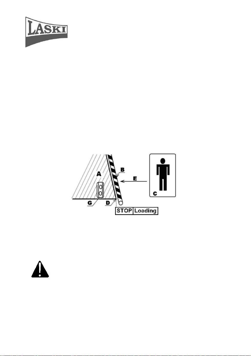
Legend:
A - loading chute, B - safety frame, C - attendant's place, D - loading chute edge,
E - infeed direction, G – buttons for control of loading and reversing
- The safety frame must be always adjusted so that the
EMERGENCY STOP must be activated before the point D – loading
chute edge.
- Do not leave the machine unattended.
30
Page 31

Chipper LS 160T
Chipping
- The chipper is powered by a tractor combustion engine. Do not
start it in confined or ill-ventilated spaces or under conditions of low
visibility.
- While chipping the chipper must always be properly coupled to a
tractor.
- It is not allowed to use the cardan shaft with its damaged guard. This guard
must be properly locked against turning. Check up locks on the sliding shaft.
- Set the discharge duct in required direction. The discharge duct cannot be
directed to the attendant's place, see following figure.
- When loading materials and during operation of the chipper the attendant
should always stand in the attendant's place, see fig.
- Having turned the chipping device on wait for speed stabilization. With that
you may soever increase or reduce the tractor PTO shaft speed. For correct
chipping functions it is necessary if the tractor PTO shaft speed is 540
rpm(1000 rpm).
- Wooden chips can be gathered in bulk or into a container located on a towing
vehicle.
- While discharging into a container, pay your attention to ejecting to avoid
ejecting chips back out off the container.
- Before displacement of the chipper to another workplace, first turn the PTO
shaft off and wait for run-out of all rotary parts. Afterwards, lift up the
machine in the top (transport) position. Never pull the machine while resting
on the ground!
31
Page 32

Chipper LS 160T
- Do not load materials with parts of metal, glass, ceramics and other similar
objects.
- Do not chip or load materials while driving.
- Having put materials in the loading chute/between loading rolls, release the
loaded material immediately and keep a certain distance from the chute.
- Do not load materials with diameters exceeding 160 mm and 3 m in length. Do
not load wooden boards with thickness more than 60 mm.
- When working, never lean over the loading chute and never pull out wooden
materials, already loaded, from the chute.
- Do not load materials with diameters exceeding 160 mm. Speed of loading
should correspond with quantity and characteristics of the material to be
loaded.
- If loaded materials are spreading with risks of catch holding of attendant's
dress being drawn in the loading chute then it is necessary to prepare such
materials accordingly (trimming, cutting).
- Pay special attention to thorny materials, such as acacia and roses, which may
easily catch your sleeves.
- Be careful while loading since materials may unexpectedly move in unwished
directions.
- In case of two attendants it is necessary to make simple signals clear before
working. During operation it is not easy to make any agreements because of
operating noise.
- Observe the working area. If any person, children or animals approach while
chipping, then stop working immediately.
- Be aware that there is a certain time period required between loading, chipping
and final ejection of chips.
- As far as possible load the chipper evenly, adapt loading speed accordingly
and keep continuous chipping.
- While loading, stand aside the loading chute.
- While loading short materials, throw them in the chute and push them forward
between the loading rolls by means of a wooden stick or a board, more than
160 cm long, to push materials between the loading rolls.
- Never use metal objects. They could cause serious damage of the loading rolls
and blades.
- When finishing the work, first wait for emptying of the loading chute.
32
Page 33

Chipper LS 160T
Recommendations:
Do chipping at rated PTO shaft speed only, i.e. at
sufficient power of the chipping wheel for ejecting chips.
Being loaded short and fine materials may deposit or clog
the space behind the loading rolls in front of the chipping
wheel. To avoid such problems and clogging put
occasionally also some longer branches.
To prolong service life of blades never put any materials
with parts of impurities, such as of metal, glass, ceramics
and other similar objects.
Optimal sharp blades reduce operating costs of the
loading and chipping equipment (reduced wear of the
chipping device).
If loaded material is free of any impurities then a grinding
interval for blades may last several months or several
hundreds m3 of loaded materials.
Blunt blades are evident on chipped edges which are not
clean but broken.
The chipper is optionally equipped with its speed regulation and the NOSTRESS
system intended particularly for tractors with power less than 30 HP.
This regulator reduces material feeding upon contingent overloading (PTO shaft
speed dropping).
The chipping wheel speed is set by the manufacturer to 900 (1100) rpm to turn the
rolls off and to 910 (1110) rpm to turn the rolls on again.
Recommendations!!
Should the loading rolls be frequently turned off while chipping,
it means that there is too much material loaded and the chipping
device is overloaded. To avoid this overloading:
reduce volume of material to be loaded, or
reduce infeed speed of the loading rolls
33
Page 34

Chipper LS 160T
The loading rolls infeed speed can be reduced by the regulating screw (see arrow
on following figure) under the hinged part of the loading chute. To change the
infeed speed, just turn the regulating screw accordingly.
Putting out of Operation
If you want to stop chipping:
- In case of loaded material wait for emptying of the loading chute.
- Wait for emptying of the discharge duct.
- Turn the tractor PTO shaft off.
Warning! The cardan shaft is equipped with a freewheel clutch. When
turned off, the rotor of the chipping device runs out – approximately 120
sec.
- Regardless of this running out, turn the switch key in the STOP position.
Emergency Situations
Put the chipper out of operation immediately in
following cases:
- If any person or animal approaches under 20 m while chipping, then stop
working immediately.
- If any breakage, damage or disengagement occurs, stop chipping immediately.
- If you heard any strange noise or vibrations or felt a strange smell while
chipping, then turn off the machine immediately and contact your dealer or
directly the manufacturer.
34
Page 35

Chipper LS 160T
- In case of fire or breakdown, stop chipping immediately.
- In case of fire use foam extinguishers only.
- If you cannot damp the fire down yourself, call for a fire brigade.
- If an attending person gets caught by rotating parts or loaded materials, stop
the loading rolls by pushing the safety frame (STOP position). Stop working
and go on only if the attending person is uninjured and fully concentrated.
- If the discharge duct gets clogged, stop loading immediately and reverse the
loading rolls by pushing the safety frame (position REVERS). Turn the PTO
shaft off and having all rotary parts stopped (after about 1-2 min) use an
elastic rod and try to release the clogged material in the end piece of the
discharge duct. Having released clogging materials, try to turn on the chipper
again. If it is not possible yet, hinge away the upper hood part and try to
remove all materials by hand (the PTO shaft must be OFF). Be aware, the
chipping wheel must be blocked properly.
- To release the discharge duct clogged, do it always at standstill only.
Technical Description
This machine consists of following main parts:
- chipping device
- loading chute
- loading rolls
- chipping wheel
- discharge duct
- frame
Chipping Device
Loading chute
The loading chute is made of welded steel plates consisting of two parts: fixed
and hinged one. The hinged part serves as an extension of the chute with a safety
frame and is protected by a terminal switch. This frame, if pushed by an attending
person or branchy materials being caught, turns the loading rolls off. The chute
itself, shaped as a square pyramid, is decreased in width toward the loading rolls
and in this way loaded materials are pressed together.
35
Page 36

Chipper LS 160T
Loading rolls
These rolls take over loaded materials and move them to the chipping wheel. Their
speed can be regulated according to the given sort of material and expected results
– chips.
Both rolls are ribbed and enable loading of materials and also pulling them out at
reverse turning if necessary (chipping wheel overloaded). Both rolls are powered
by a hydraulic motor.
If required, both rolls are outwards movable in order to adapt working to the
material to be loaded.
This machine is equipped also with loading speed regulation with sensing actual
speed of the chipping wheel. Assessment of actual speed and following speed
regulation are controlled by the NOSTRESS unit.
Chipping wheel
It is a steel disc serving also as a flywheel for absorption of shocks while chipping.
This wheel is put in ball bearings; a drive pulley is fitted on its shaft. The wheel is
equipped with two blades for cutting of loaded materials. Vanes welded on its rear
side serve for ejecting chips in the discharge duct.
The chipping wheel is installed in a rigid frame and protected by a steel plate. Its
protective shield consists of two parts and particular parts are bolted together. By
safety reasons the upper part is protected with a terminal switch for turning the
drive off if the shield was opened or got loose.
Discharge duct
This duct continuously extends the chipping wheel shielding and serves for
directing the ejected chips. The duct is turnable and its end piece (tilting gate)
serves also for setting the range of ejected chips.
Frame
This machine is attached to a rigid frame welded from hollow-space profiles. In the
front part there is a three-point hitch welded and intended for coupling to a tractor.
In the bottom frame part there are a belt gear and the machine input shaft.
36
Page 37

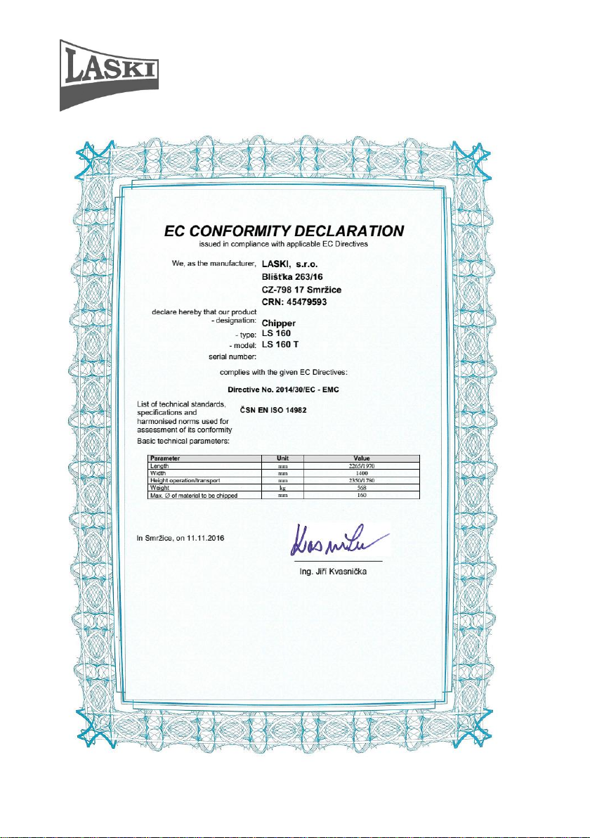
Chipper LS 160T
Parameter
Unit
Value
Overall length/transport length
mm
2265/1970
Overall width/transport width
mm
1400
Overall height/transport height
mm
2350/1780
Weight
kg
568
Chipping device:
Chipping wheel – diameter
mm
600
- number of blades
-
2
- rate of cutting
m.s
-1
40
Max diameter disposed materials
mm 160
Chipping wheel drive
-
3 x belts XBP 1700 Ld
Loading device:
Infeed hole size
mm
240 x 170
Number of loading rolls
-
2
Diameter of rolls
mm
160
Feeding speed
m.s-1
10 - 35
Drive
-
hydrostatic
Loading roll speed for turning-off
min
-1
900 (1100)
Loading roll speed for turning-on
min-1
910 (1110)
Speed regulation - NOSTRESS II
Loading chute:
Feeding profile
mm
1040 x 800
Drive:
Type
-
tractor PTO shaft
PTO shaft speed
min-1
540 (1000)
Shaft
-
six-spline
Hydraulic oil: - OH HV 46
ISO VG 46, ISO 6743/4 typ HV
CETOP RP 91 H Category HV
DIN 51 524 část 3-HVLP
Poclain P00552-13P
Hydraulic pump drive
-
1 pc belt XPA 1180Ld
Capacity of hydraulic oil tank:
l
15
Electric wiring
Supply voltage V 12
Coupling
Type, category
-
rear three-point hitch, cat. 1 or 2
Technical Parameters
Maintenance
- Any servicing of the chipper should be carried out by authorised
persons only.
37
Page 38

Chipper LS 160T
Grease cup of chipping wheel (left) and
sliding guides of loading rolls
Lubrication every 40 running hrs
(LTA 3EP MOL Lition)
Grease cup on input shaft Lubrication
every 40 running hrs(LTA 3EP MOL
Lition)
- Check up the machine for completeness and its general condition.
- Any maintenance and servicing on the machine can be done at standstill only,
i.e. the PTO shaft off, the switch key being pulled out from the ignition box,
tractor wheels blocked against unwished motion.
- While servicing the chipper should be lowered on the ground.
- Pay special attention to all safety elements.
- Check up V-belts for tightness and wear.
- Keep regular intervals for lubrication of bearings.
- Check up condition of blades and chipping wheel vanes regularly.
- Check up hydraulic hoses for wear. Replace them if necessary or every five
years.
Lubrication
38
Page 39

Chipper LS 160T
Grease cup of chipping wheel (right)
Lubrication every 40 running hrs(LTA 3EP MOL Lition)
Blade Grinding
Blades, fitted on the chipping wheel, are double-sided, i.e. reversible if one side is
blunt.
Blades edge regrinding requires high demands for keeping cutting edge shape.
While grinding it is necessary to keep its optimal geometry, see following figure.
Proper shapes prolong blade service life.
While regrinding it is necessary to keep the same weight of particular
blades because of balance of their rotating mass. For grinding use
always a grinder with its magnetic table and a special jig.
Detailed geometry of blade edge
39
Page 40

Chipper LS 160T
Grind every blade only up to minimum distance from edge to its fixing
bolt. i.e. 37,5 mm. This distance on a new blade is 100 mm, see
following figure.
Max. wear/grinding of cutting edge
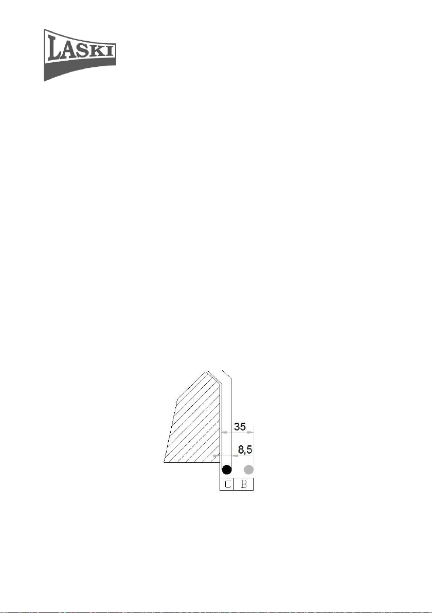
Chipping Adjustment
Optimal operation of the chipping device requires proper setting of a clearance
between the blade and the opposite cutting edge. This distance should be set (see
following figure) and checked after fitting ground blades, then it grows with their
wear and chipped branches may be squeezed between the blade and the opposite
edge. It brings deterioration in quality of chipping.
Pay attention also to blades exchange. In such case set the given clearance bigger
to avoid damage of a new blade and its opposite cutting edge.
40
Page 41

Chipper LS 160T
Recommendation: Check out conditions of blades every 40 operating hours.
Regrind blade edges if they are found blunt
Jointing elements (bolts and nuts) should be replaced together with The
blades exchange. Safety nuts should be used only once, since they lose
their self-locking properties if used repeatedly. The fixing bolts should
be tightened with torque of 100 Nm
NOSTRESS System – Speed Regulation
This system is intended for overload
protection of the combustion engine
consisting of an electronic control unit and a
speed sensor installed on the rotor shaft.
Control unit:
This control unit displays actual rotor speed
values. When the rotor stops, the unit
displays a total number of running hours
"TH" or a daily number of running hours
“DH”. To reset the current daily number, just
press both arrow buttons together, set up
the access code to “3003” and enter the main user menu. Select the submenu
“delete daily hours” and confirm the function “delete”.
Right function of NOSTRESS system:
The speed regulator reduces material feeding upon contingent overloading. For
example, the chipping wheel speed is set to 900 (1100) rpm to turn the loading
rolls off at speed loss and to 910 (1110) rpm to turn the rolls on again. Actual rotor
speed values are displayed on the control unit. However, actual engine speed
values are not displayed.
This control unit enables to set the speed according to the material to be loaded:
F1 – light branch-wood, shrubbery, twigs, hedges
41
Page 42
Chipper LS 160T
Location of sensor under hood
F2 – medium hard wood, branch and leaf wood
F3 – hard wood, needle-leaved trees, bough, timber
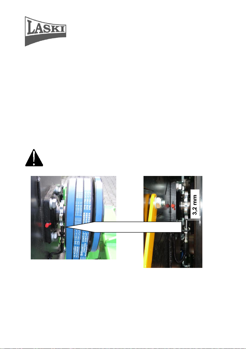
Speed sensor:
This encapsulated sensor in fitted on a holder keeping its distance of 3,2mm from
the cam lobe. In the rear part of the sensor sleeve there is an orange LED installed
flashing in case of proper sensing.
Set-up of the speed sensor distance should be done at
machine standstill only
42
Page 43

Chipper LS 160T
NOSTRESS system protection against overvoltage
Overvoltage occurrence in the electric installation blows the fuse and breaks the
TVS diode (Transient Voltage Suppressor / Transil) used to protect
sensitive NOSTRESS electronics against voltage spikes. Should the fuse (7,5 A) be
blown again, first replace the damaged TVS diode and then put a new fuse.
43
Page 44

Chipper LS 160T
V-belt Tension
It is necessary to pay special attention to the routine maintenance and proper belt
tension adjustment because the V-belts on this machine transfer the engine torque
to the chipping wheel and the hydraulic pump.
For belt tension adjustment remove two side belt guards fixed here by fixing bolts.
Under these guards there is a belt gear for power transmission to the chipping
wheel and the hydraulic pump.
While tightening the belts proceed as
follows:
- Check up tension of new belts after
first 5 service hours and
afterwards always in intervals of
25 hours. Excessive slipping or
excessive tension will wear out the
belts prematurely and reduce their
life essentially.
- Adjustment of particular belts on the
hydraulic pump and on the chipping
wheel can be done independently.
- In case of three V-belts for the
chipping wheel it is necessary to
shift the belt pulley on the input
shaft.
- For adjustment of the belts for the hydraulic pump it is necessary to shift the
pump body.
44
Page 45

Chipper LS 160T
Belts as to drive (belt
pulleys)
Finger pressure F
/N/
Slack p /mm/
Input shaft – chipping wheel
50
12
Chipping wheel – hydraulic
pump
50
7,5
Recommended belt slack and finger pressure values, see the following chart:
While tightening the belts proceed as follows:
Chipping wheel drive
- Loosen four nuts on the stretching bolts in the direction intended for pulley
shifting. For tightening loosen the nuts over the supporting plate and also the
nuts directly on the plate uniformly by 0,5 – 1 turn to let the belt pulley slide.
Having reached the recommended belt slack value, retighten all the bolts by
means of their lock nuts.
45
Page 46

Chipper LS 160T
Hydraulic pump drive
Loosen four nuts of the fixing bolts holding the pump on the frame
uniformly approximately by 0,5 turn to let the pump slide in the intended
direction by means of the stretching bolt. Having reached the recommended
belt slack value, retighten the fixing bolts on the frame and the lock nut on the
stretching bolt. To make all the bolts accessible first it is necessary to remove
the belt guards over the belt pulley of the chipping wheel shaft.
Having finished the belt tension adjustment, replace the belts
guards.
Hydraulic oil filter change
The oil filter is installed in the hydraulic circuit and accessible left under the
loading chute.
We recommend changing the oil filter element always together with the hydraulic
oil change. This oil filter element is in fact a replaceable cartridge fixed on the
central bolt of the filter body. For its exchange it is necessary first to loosen it by
means of a special wrench.
Before filling new oil first screw up a new filter element.
Fill the hydraulic oil tank up to 17 litres only (up to the MAX mark on the oil
tank).
It is strictly forbidden to put this chipper into operation without
any oil filter or with its filter element clogged or damaged.
Replace the filter element only at stillstand of the machine.
Hydraulic oil temperature should be lower than 45oC.
46
Page 47

Chipper LS 160T
Electric
Installation
Protect all wires against contact with oil products. Keep all
elements clean and avoid any damage of wires - short circuit
risk. All connections must have clean and proper contact
surfaces to avoid intermediate resistance at a wrong contact
point.
Hydraulic Oil
Change
Do the first oil change after the first 500 running hours or after
the first season. Next oil changes always after 1000 running
hours. It is recommended changing the filter element together
with the oil change.
Hydraulic Oil
Filter Change
We recommend changing the filter element together with the
oil change.
Full-flow filter allocation
Maintenance Intervals
47
Page 48

Chipper LS 160T
Operation
Component
Interval (hrs)
10
100
250
500
1000
2500
5000
Exchange
Hydraulic oil in circuit
*
Hydraulic oil filter
*
Checking
Hydraulic oil in tank
*
Cleaning
Hydraulic oil tank
*
Failure
Cause
Remedy
Wrong chipping
or loading
Blunt blades
Remove and regrind blades. If worn,
replace them for new ones.
Worn opposite cutting
edge
Remove and regrind cutting edge; set
optimal clearance between blade and
opposite cutting edge
Malfunction of loading
rolls
See Problems with hydraulics
Wrong angle geometry
Regrind in accordance with detailed
figure of edge geometry
Damage/wear of
loading rolls
Replacement
Too small, dry or rotten
materials
Mix before loading
Loading rolls do not
turn – rotor runs idle
Wrong setup of sensor for turning the
loading rolls on
service
Tractor engine
overloaded while
chipping
Wrong sensor setting
for min. speed
Switching-off speed is set too high
service
Blown fuse in
regulation circuit
Fuse replacement
Faulty control unit in
regulation circuit
Replacement
Speed sensor defective
Replacement
Loading rolls do not
turn
Safety circuit not closed
Tilt rear part of the loading chute and
check up hood position protected with
terminal switch
Checking, Oil Exchange
(*) clean daily under special conditions
(**) clean every 4 – 5 hrs under extreme dusty conditions
(***) see recommended oils
(o) if clogging indicated
() first exchange
Failures and Troubleshooting
48
Page 49

Chipper LS 160T
Throttle valve closed
Check up manual speed regulation for
loading
Loading activated
Press the green button for loading
Failure of NOSTRESS
system
Measure voltage on coil of
electromagnetic valve; it should be 0
at max. speed
Faulty coil of
electromagnetic valve
Coil replacement
Broken leads
Check up wiring for integrity
Faulty hydraulic pump
Check up oil pressure
Pump replacement
Faulty electric
switchboard
Coil replacement
Loading rolls turn off
also while chipping
Loading rolls cannot
be set in motion again
after turning the
machine off
Excessive speed of
chipping wheel and
PTO shaft
Reduce the PTO shaft speed
Working speed of the chipping wheel
must not exceed 1500 rpm.
Blades touch opposite
edge
Wrong setting of
clearance
Set distance to 0,5 – 1 mm
Loosen blade bolts
Tighten up fixing bolts
Clearance of chipping
wheel bearings
Tighten up fixing bolt of wheel on its
shaft
NOSTRESS system
out
of function
Blown fuse
Replacement of fuse 7,5 A
Faulty electronic
control unit
Replacement of fuse 4 A (inside
control unit)
Faulty speed sensor –
LED is not flashing
Check up wiring
Loading chute gets
clogged
Sensor replacement
Discharge duct gets
clogged
Too low speed of PTO
shaft
Stop loading and increase speed at
chipping. Min. working speed of PTO
shaft at chipping is 350 rpm
Discharge duct
deformed
Repair/replacement
Too small, dry or rotten
materials
Mix before loading
Loading rolls
overloaded with
material
Reduce loading roll speed
49
Page 50

Chipper LS 160T
Bearings overheated
Insufficient lubrication
or wrong lubricant used
Lubrication and lubricants should be in
accordance with recommended
intervals and sorts (LTA 3EP MOL
Lition)
Too high speed of
chipping wheel
Working speed of the chipping wheel
must not exceed 1500 rpm.
Bearing loosened
Tighten up bearing housing bolts with
required torque
Bearing worn
Replacement
Waste Disposal
Any waste materials resulting from the machine operation should be disposed
in accordance with laws and regulations applicable in the given country.
Protect nature and water resources against used oil and filter elements.
Any parts of the machine should be disposed in accordance with laws and
regulations applicable in the given country.
50
Page 51

Chipper LS 160T
Warranty
The manufacturer provides warranty on this product for a period as stated in the
enclosed Warranty Certificate. The given warranty period begins after delivery to
the customer.
This warranty covers all failures resulted from faulty assembly, manufacture and
used materials.
The manufacturer bears no responsibility for damages resulted from own user's
wrong usage, such as:
Usage by an unauthorised person.
Unauthorised changes, repairs and actions on the machine.
Usage of unoriginal spare parts or parts intended for other
models.
Disobedience to instructions for use.
Damage of the machine caused by faulty handling, maintenance
or overloading.
This warranty does not cover faults resulted from damages
caused by the user.
This warranty does not cover parts being subject to ordinary wear
and tear.
This warranty does not cover any damage of machine caused by
usage of unoriginal spare parts.
This warranty does not cover consequences resulted from
weather effects.
Any warranty claims must be submitted in writing with papers concerning
acceptance for warranty or post-warranty repair.
51
Page 52

Chipper LS 160T
Service Report
52
Page 53
Chipper LS 160T
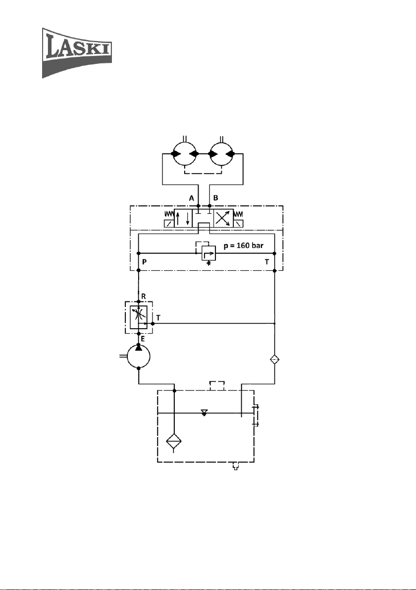
Hydraulic scheme
53
Page 54

Chipper LS 160T
ELEKTRICKÉ ZAPOJENÍ / ELEKTRISCHE SCHEMA / WIRING DIAGRAM
54
Page 55

Chipper LS 160T
ELEKTRICKÉ ZAPOJENÍ / ELEKTRISCHE SCHEMA / WIRING DIAGRAM
55
 Loading...