

Page 1
OPERATING INSTRUCTIONS
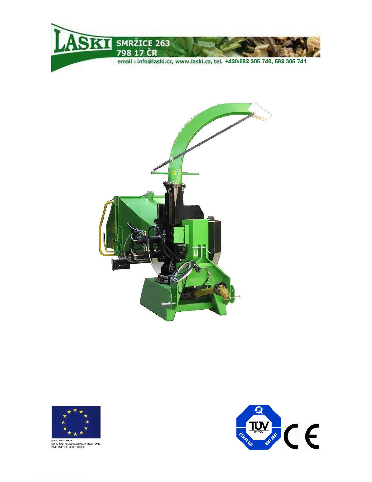
CHIPPER
LS 150 T
Orig. version: 08.2016
Page 2
2
Foreword
Thank you very much that you have just purchased our product, the chipper
LS 150 T. Our company has been engaged in production of equipment for wood residues
crushing and disposal for many years and has gained considerable experiences in this field.
Quality of our small and also powerful machines is proven in 40 countries of Europe and Asia
we export to.
Permanent innovation of the Laski s.r.o. manufacturing assortment was crowned by the Gold
Medal for our complex family of shredding and chipping equipment KDO and LS at the
occasion of the International Trade Fair.
Grand Prix Techagro 1998
Grand Prix Silva Regina 2002
Grand Prix Silva Regina 2008
This manual brings important instructions for users, i.e. instructions for putting the machine
into operation, work safety and operating experiences. You will learn how to carry out
maintenance, repairs and servicing and who is authorised for doing checks and other actions
on the machine.
Your local dealer will give you this manual with instructions for operation and maintenance
while taking this new machine over. Make sure, if you understand everything. If not, do not
hesitate and contact your dealer and ask him for explanation. It is very important for you and
your work safety to understand all instructions given in this manual.
The firm Laski spol. s r.o. does not bear any responsibility for any claims resulting from
disobedience to the instructions given in this manual.
This operation manual includes also work safety instructions in various parts of the text. If
there is any work safety rule or instruction in general description, then this instruction is
indicated with the following symbol:
Page 3

3
Contents
FOREWORD ........................................................................................................... 2
CONTENTS ............................................................................................................. 3
PRODUCT IDENTIFICATION ........................................................................... 5
WORK SAFETY INSTRUCTIONS ..................................................................... 8
UTILISATION ......................................................................................................... 8
NOT ALLOWED USE .............................................................................................. 8
GENERALLY .......................................................................................................... 8
WORK SAFETY SYMBOLS .................................................................................... 14
TRANSPORT OF PRODUCT/HANDLING ................................................................. 15
PRECAUTIONS IN DESIGN .................................................................................... 16
CONTROLS .......................................................................................................... 18
USE ........................................................................................................................ 19
TRANSPORT SAFETY ........................................................................................... 19
STORAGE ............................................................................................................. 21
BEFORE PUTTING INTO OPERATION .................................................................... 21
COUPLING TO TRACTORS .................................................................................... 23
PUTTING INTO OPERATION .................................................................................. 24
CHIPPING ............................................................................................................ 25
PUTTING OUT OF OPERATION .............................................................................. 29
EMERGENCY SITUATIONS ................................................................................... 29
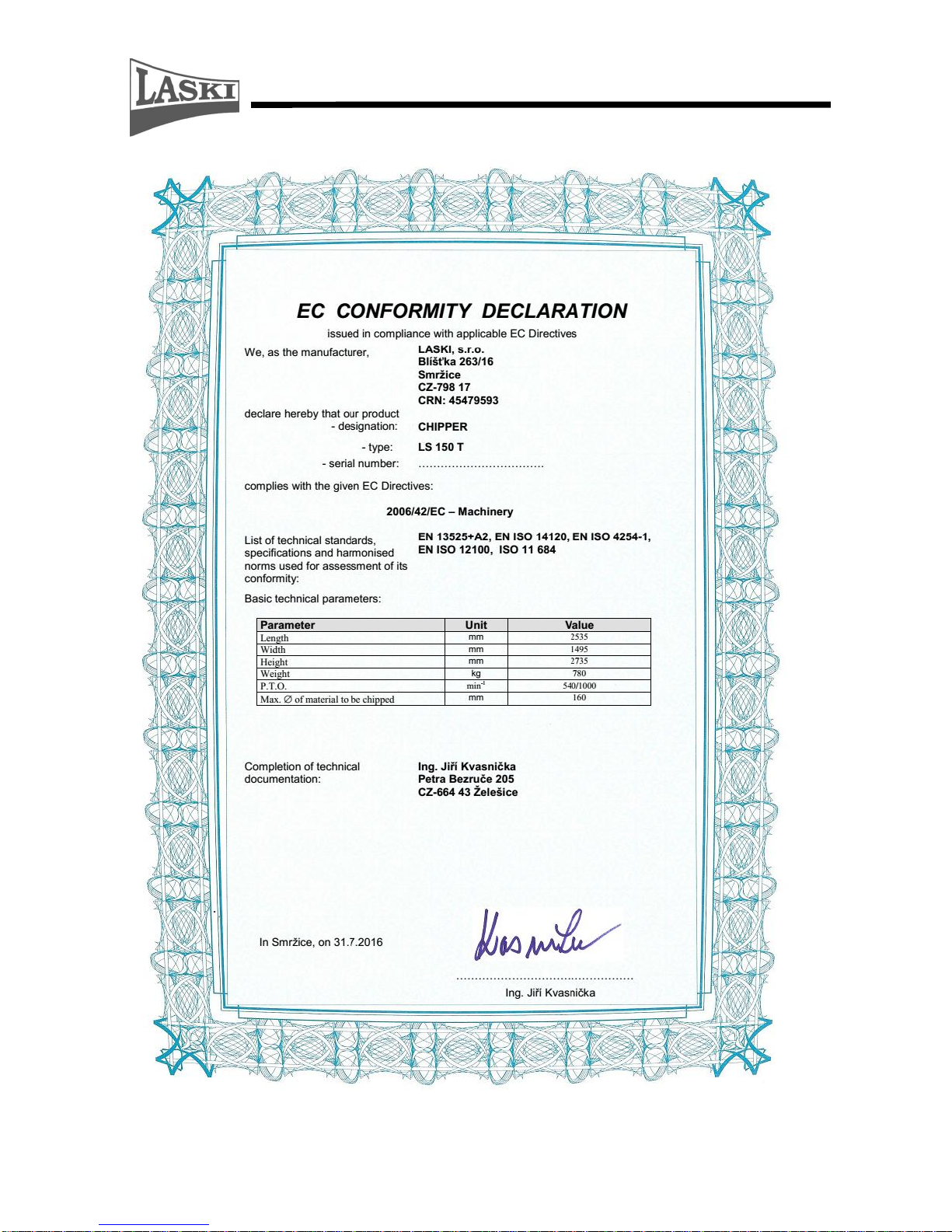
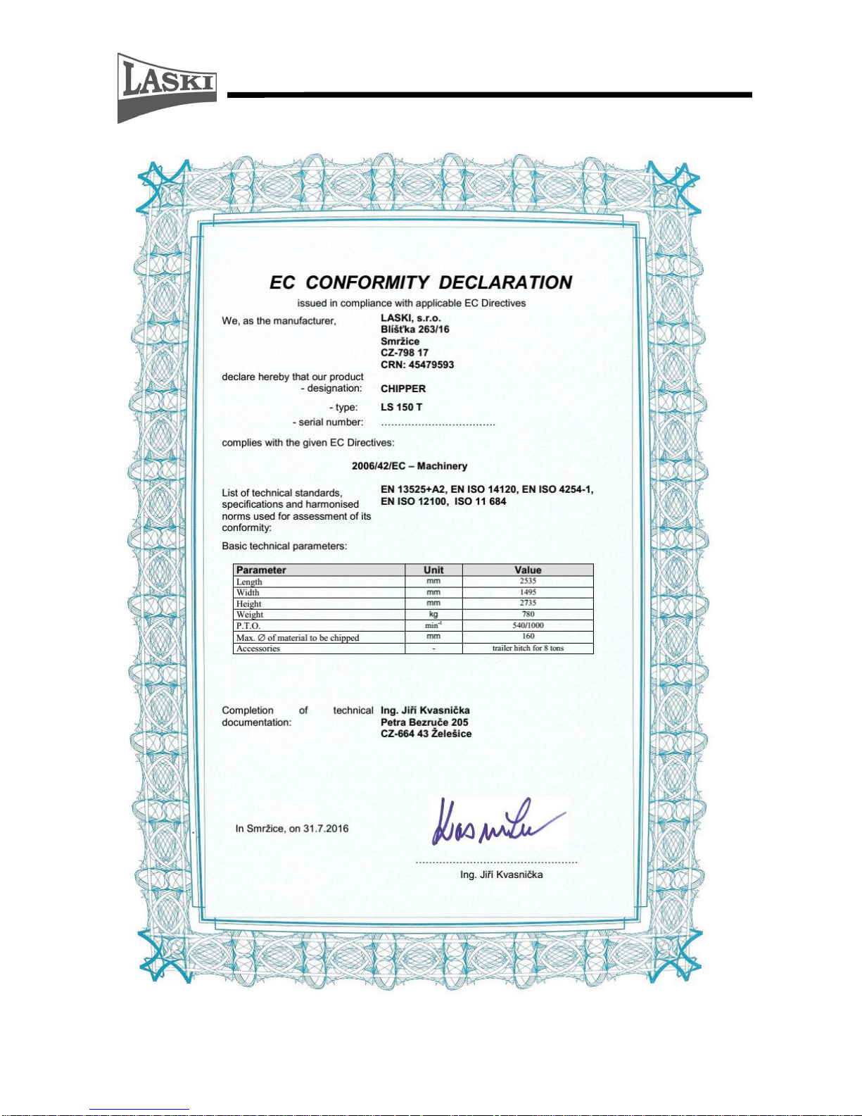
TECHNICAL DESCRIPTION ........................................................................... 30
Chipping Device ............................................................................................. 30
Frame ............................................................................................................. 31
Technical Parameters..................................................................................... 31
MAINTENANCE ................................................................................................. 32
Lubrication ................................................................ ................................ ..... 32
Blade Grinding ............................................................................................... 33
Chipping Adjustment ...................................................................................... 35
NOSTRESS System – Speed Regulation ......................................................... 36
NOSTRESS SYSTEM PROTECTION AGAINST OVERVOLTAGE ............................... 37
Maintenance Intervals .................................................................................... 38
Checking, Oil Exchange ................................................................................. 39
Page 4

4
FAILURES AND TROUBLESHOOTING .................................................................... 39
WASTE DISPOSAL ............................................................................................... 41
USE OF THE CHIPPER EQUIPPED WITH A HITCH ..................................................... 41
WARRANTY ........................................................................................................ 44
SERVICE REPORT ............................................................................................ 46
Page 5
5
Page 6
6
Page 7
7
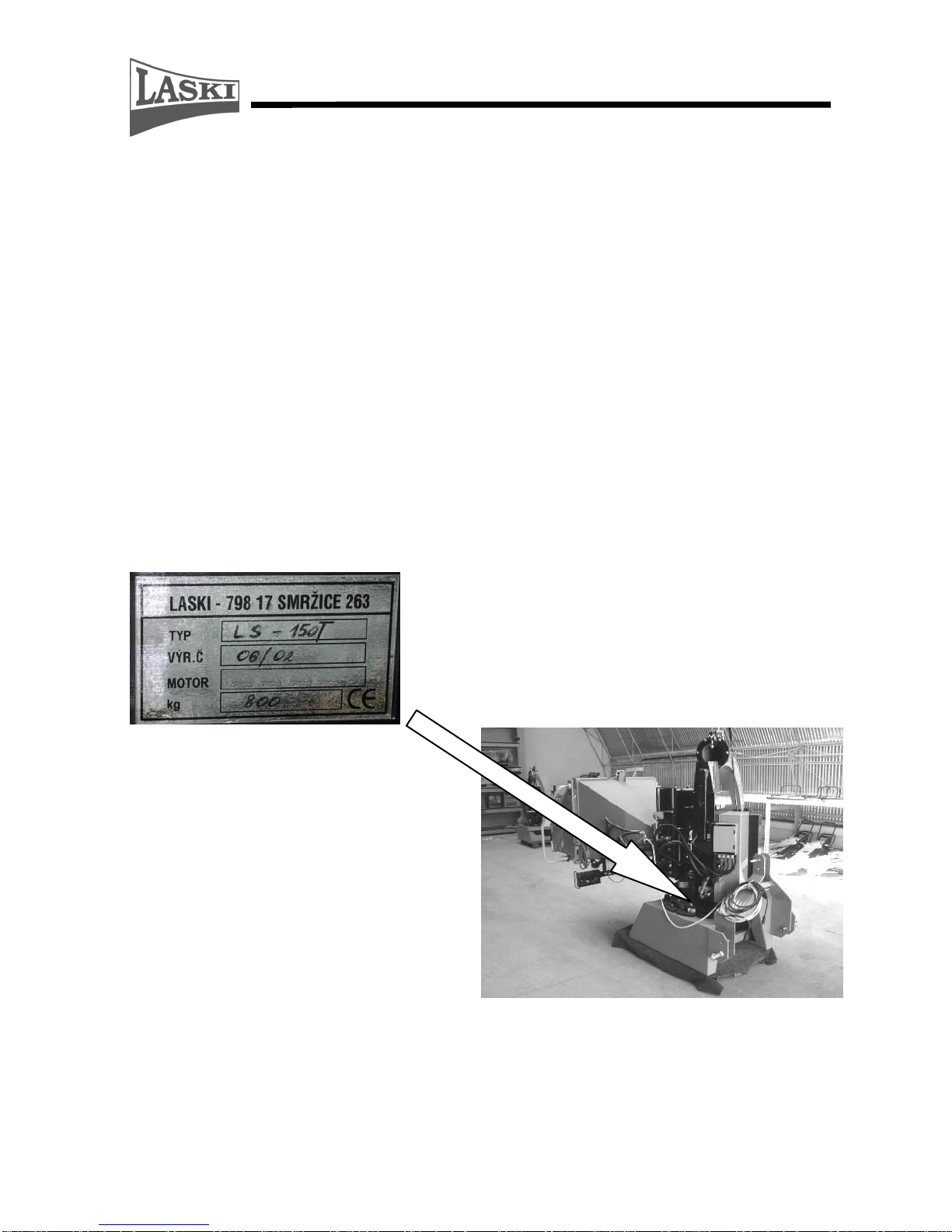
Product Identification
Our product is identified with its serial number stamped in its type plate on the frame. Upon
take-over of the product we recommend you to fill required data in the following form
concerning the given product and your dealer.
Type of product:
…………………………………………………….
Serial number of product:
……………………………………………………..
Dealer's address:
……………………………………………………..
Address of authorised service:
……………………………………………………..
Date of delivery:
……………………………………………………..
Warranty expiration date:
……………………………………………………..
Interruption of warranty period:
……………………………………………………..
This type plate includes:
- manufacturer's
data
- type
- serial number
- weight of machine
Page 8

8
Work Safety Instructions
Utilisation
This chipper, being coupled with a tractor three-point hitch, is designed for
disposal of wood waste, twigs, barks, branch-wood and other above-ground
biomass or for manufacture of chips from aforesaid materials and also for disposal
of redundant timber, such as sticks, deals, pickets etc. The chipper can dispose all
these materials with diameter up to 160 mm or flat boards and plates with thickness
up to 60 mm. These wooden pieces must be free of metal, glass and other similar
objects. While working, the chipper must be relatively levelled.
The chipper should be controlled and operated by two attendants who in turns load
materials to be chipped in a loading chute.
Not Allowed Use
The chipper is not allowed to be used for disposal of aforesaid materials with
foreign matters and objects, such as metal, steel binding bands, glass cullet, stony
debris, ceramics etc.
It is not allowed to use the chipper in the presence of unauthorised persons who
may stand or move in direction of discharge ducting. At work in residential zones
use the machine in accordance with regulations of the local authorities to avoid
disturbing of local inhabitants (noise level). It is not allowed to use the chipper, if
its loading chute height above the ground is less than 600 mm and if its cardan
shaft is deformed or damaged.
Generally
- This machine is allowed to be operated only by attendants who are over 18 yrs
old, physically and mentally capable and demonstrably instructed with its
operation.
- One of two attendants at least (a tractor driver) should have a respective
driver's license, group "T".
- This machine can be operated by two persons only.
- Any training course for attending personnel should include also practical
operation under supervision of an experienced person or your dealer and
necessary work safety instructions.
- Before working learn all functions of individual controls and safety elements
(safety frame) and carry out functional checks before any use. Check
especially loading of materials, i.e. the controller frame. By pushing the
Page 9
9
concerned controller in infeed direction this machine must stop loading
materials and by its next pushing the loading rolls should turn back while
being under permanent pressure (pushing). The controller frame have to be
advanced in front of the hinged loading chute edge so that the attendant stops
the loading rolls, or let them turn back, at pushing by using parts other than
hands (e.g. shoulder, elbow, hip, legs etc.).
- It is strictly forbidden to change or to set the controller frame so that the STOP
position is under the loading chute edge.
10
- To stop loading it is also possible to press the STOP button under the loading
chute.
- It is forbidden to tighten the fixing nuts on the safety frame with intend to
increase its resistance against unwished switching off. Required force for
switching control should remain on values preset by the manufacturer, i.e. up
to 80 N in the lower horizontal frame part.
- Any removal of safety elements and guards from the machine and any further
operation without them are strictly forbidden.
- While chipping it is not allowed to enter the area of ejected flying wooden
chips.
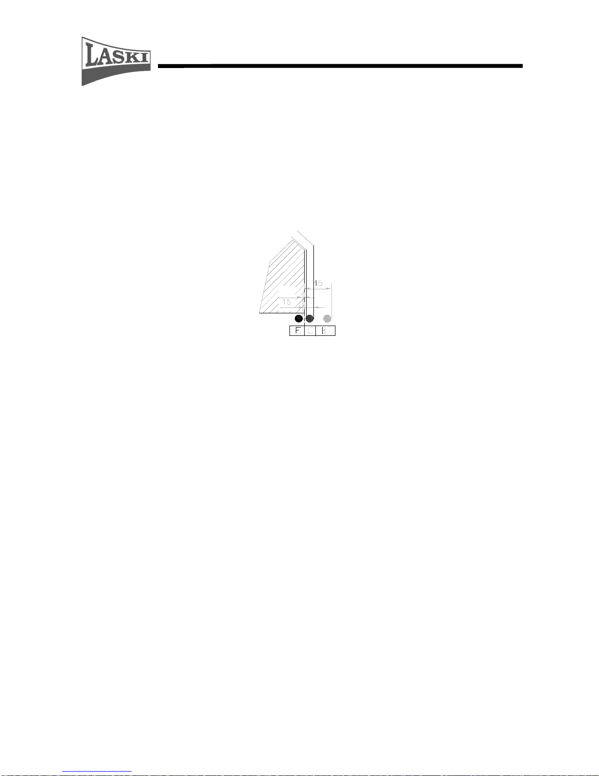
- The end piece of the discharge duct (its upper turnable part) can be set only in
angles, see following figure. Never direct it toward the attendant's place!!
Page 10
10
- While working the chipper should rest on the ground.
- Keep this machine beyond children's and unauthorised person's reach. Avoid
their attendance while chipping.
- When using the chipper without any container or closed bin, keep anybody
beyond the area where chips are being thrown.
- When using the chipper with such a bin, never look inside if the chipper is still
working.
- When leaving the machine take always the switch key out of ignition.
- Every operator of this machine is fully responsible for any injury or damage
caused to the third persons within the operating reach of the machine.
- At work in residential zones use the machine in accordance with regulations of
the local authorities to avoid disturbing of local inhabitants (noise, flying
chips).
- Warning !!! Be aware of ejected particles. They have substantial kinetic
energy. If the loaded wooden material contains not allowed parts, such as
metal, sand, glass etc., then such objects can reach a longer distance than
wooden chips. Direct the discharge duct to regulate its ejecting as needed.
- Instructions for use of the cardan shaft operation and the trailing tractor are an
integral part of this manual and should be always respected.
- While coupling the chipper to a tractor do not stand between its towing bar
and a tractor. Do not stand behind a towing tractor while backing. Ask other
person to help you with coupling.
- First it is necessary to couple the cardan shaft to the chipper input shaft, then
the lower linkage, the upper drawbar of the three-point hitch and finally the
tractor PTO shaft.
Page 11

11
While chipping the operator is obliged:
to use only such a chipper which is in optimal operating condition, not
damaged through transport, storage of from previous operation,
to check functions of all controls and safety elements, particularly the
controller frame, before putting the chipper into operation,
to avoid disturbing of other people with noise, exhaust fumes or ejected flying
particles (at windy weather),
to keep traffic rules and local regulations when going or working on or nearby
public roads,
to turn the machine off if the discharge duct is clogged.
Clean the duct at standstill only. For cleaning use only suitable hooks or bars
to release pressed materials. After repeated putting the chipper into operation
let the machine run idle in the chipping mode to empty the whole discharge
ducting. If proper cleaning is required, then take always the switch key out of
ignition before removing its hoods.
When working never lean over the loading chute and never push wooden
materials with your hand or leg only. Use always a wooden stock or a bar to
push materials between the loading rolls.
While working wear always personal protective equipment - protecting shield
or goggles, protective gloves, working shoes and working cloth properly
buttoned. Avoid wearing free parts, such as ties, scarves and shawls, belts etc.
In case of longer hairs use always a proper head piece. Otherwise, such a
person is not allowed to operate this machine.
In case of two attendants it is necessary to make simple signals clear before
working and to appoint one who will manage the work.
If any object, not allowed to be chipped, falls down into the loading chute, do
not try to pull it out with your hand. It is very hazardous for your health and
operational safety. Turn always the machine off.
- Keep traffic lights and work safety symbols in proper order.
- Check materials to be loaded and remove all undesirable objects. If you see
such particles in ejected chips, stop working immediately.
- This manual describes problems and faults which could occur at work and
which may be remedied by an instructed person. In case of other problems and
faults do not hesitate and contact the manufacturer. He is always ready to help
you.
- Never do any technical changes or any actions which are neither given in this
manual nor allowed by the manufacturer. The machine, not correctly installed
or adjusted, may run without problems now but in the future it could damage
Page 12

12
any of important parts. Pay regular attention to all joints and bolts. Keep them
properly tightened.
- Do not put any objects or tools on the machine.
- The manufacturer does not bear responsibility for any damages or injures
caused to the third persons or to other equipment resulted from disobedience
to instructions given in this manual.
- When handing the machine over to another person make sure if all controls,
guards and other safety elements are complete and fully functional.
- Never remove guards and other safety elements. They serve for your safety.
- Keep the given intervals for checks of bolted joints.
- Always after work clean all parts of the machine properly. Pay your attention
especially to any oil spots or fuel leakage. Clean any oily spots.
- Some parts of the machine can be hot while in operation. Avoid any settling of
flammable chipped materials on such parts or close to fuel tank, hydraulic oil
tank and exhaust manifold. Stop working if such deposits exceed 1 mm.
- Any servicing can be done only if the machine was put out of operation, its
battery was disconnected and the cardan shaft was uncoupled. If the chipper is
still coupled to the three-point hitch, block the tractor (wheels) against
unwanted motion.
- Do not use petrol as a cleaning agent.
- Keep open fire away while filling the tank.
- Keep the machine beyond reach of open fire.
- Some parts of the machine run warm, such as hydraulic elements, belts and
pulleys. Do not touch them when the engine is still running or having been just
stopped.
- Do not let the engine running in high speed unreasonably.
- Do not start the machine in confined or ill-ventilated spaces.
- Combustion gases outgoing from a tractor are toxic!
- Do not use the machine under conditions of low visibility, especially at foggy
weather on public roads.
- Do not use the machine without prior reading this manual.
- Do not carry out any repairs that are specified for authorised services only.
- Do not carry out any repair where its solution exceeds your experiences.
- It is strictly forbidden to work with the chipping device damaged (out-of-
balance, vibrations while running).
- While servicing the chipping device, or in the vicinity thereof, it should be
always blocked against unwilling motion (with its safety pin inserted).
Page 13

13
Before transport on public roads:
Set the machine in the transport position, i.e. with its discharge duck tilted
backwards and locked against motion. Be aware that traffic lights must remain
visible.
Couple the chipper to a towing vehicle properly and check proper pin
coupling.
Plug and check traffic lights of the chipper.
If necessary, remove all mud, especially from tires, before coming to a public
road.
Transport on public roads
When going on roads the chipper must be lifted at least 25-30 cm above the
ground.
Any transport on public roads is allowed only with the PTO shaft turned off
and the discharge duck tilted.
Any transport of persons or of any load on the machine is not allowed.
Never exceed max. allowed transport speed.
While putting the coupled chipper aside block the tractor wheels against
unwilling motion by means of scotch blocks.
Pay attention to handling performance on roads. Cornering, turning, braking
make new demands on driving.
Adjust driving speed to ambient conditions, especially at turning, obstacle
crossing, exits to plots etc.
This machine is approved to transport on public roads. Some restrictions are
given in your registration papers. Take these papers always with you.
Before coupling to a tractor check up the allowed weight limit in the tractor
hitch and compare it with the weight of your chipper. If a load on the tractor
front axle is less than 20% total weight, any coupling to a tractor is forbidden.
Note: Be aware that traffic rules and regulations in different countries may differ.
Page 14
14
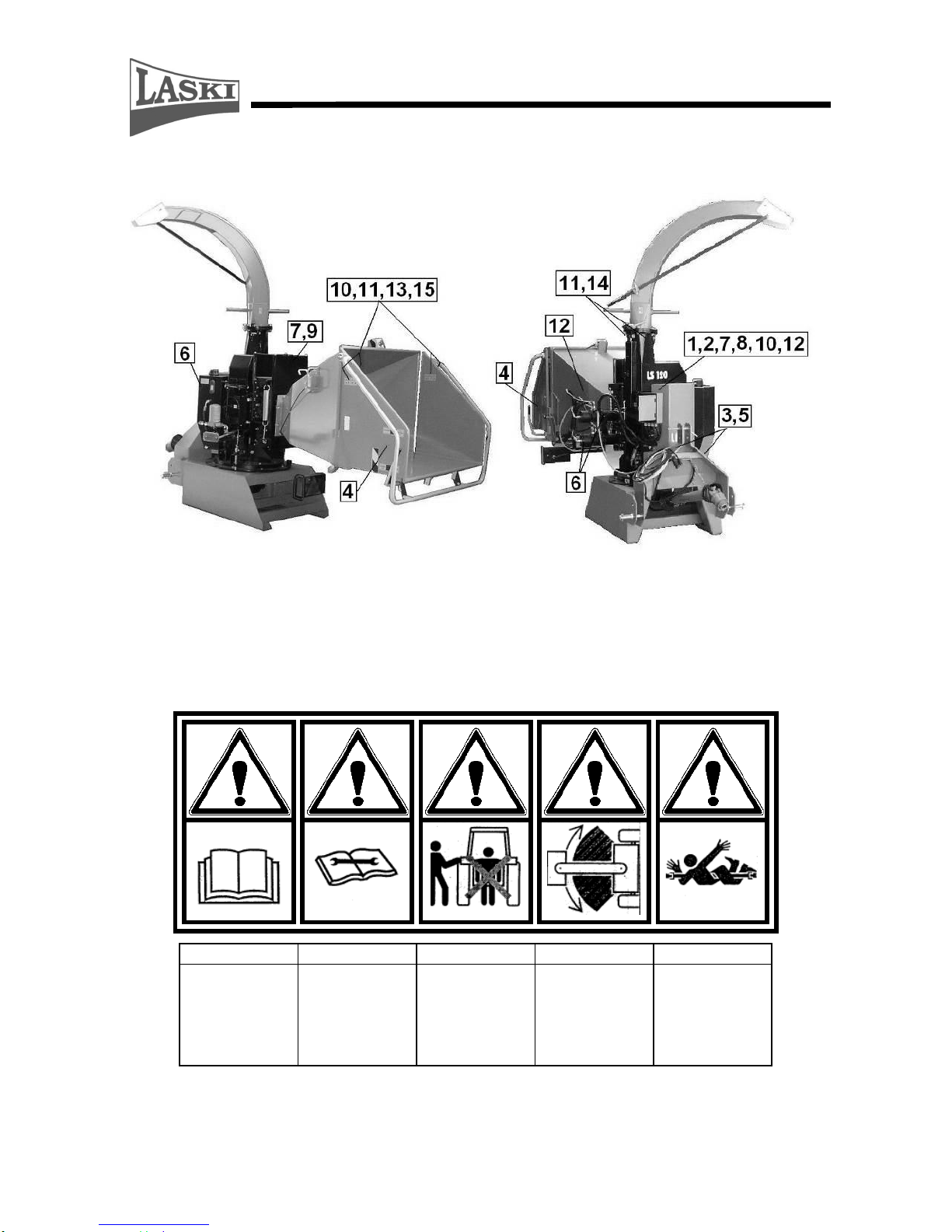
Work Safety Symbols
This article introduces work safety symbols (pictographs) used on this machine.
Under the given pos. number there is their location on the machine. These work
safety symbols warn the operator against risks connected with the machine use.
Your respect to the symbol meanings is a precondition for your work safety.
1 2 3 4 5
Read this operating
manual before use.
Always follow the
manual while
maintaining,
servicing or repairing
the machine and take
always the switch
key out of ignition.
Do not stand
between tractor and
equipment while
coupling.
Warning! It swings
out while turning.
Warning! Rotating
parts - accident risk.
Page 15
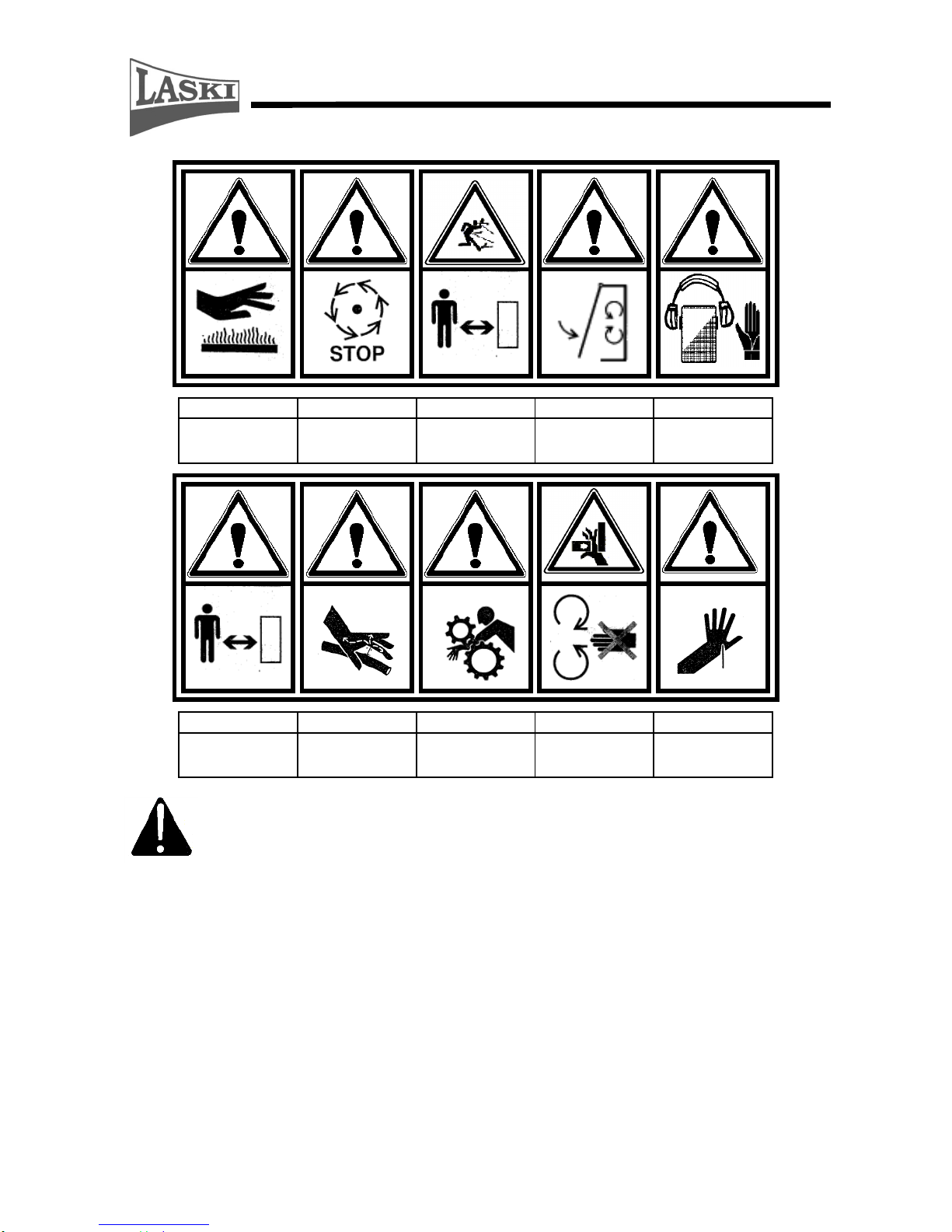
15
6 7 8 9 10
Warning! Hot parts.
Warning! Turning
part is running out.
Warning! Ejected
objects hazard. Keep
away.
Warning! Close all
guards before
starting the machine.
Wear personal
protective
equipment.
11
12
13
14
15
Keep safety distance.
Warning! Risk of
high-pressure liquid
leakage
Warning! Rotating
rolls. Pull-in hazard.
Warning! Hazard of
extremity injury by
rotating part
Warning! Accident
risk.
The user is obliged to keep all the work safety symbols legible, clear and
undamaged. In case of any damage or illegibility ask your local dealer or
an authorised service for a new relevant pictograph.
Transport of Product/Handling
- This product is delivered completely mounted and fitted on a wooden pallet.
- While handling the chipper you may use a lift truck.
- After coupling to a tractor any further handling is possible only according to
tractor technical parameters. The chipper should not bring any negative
impacts on tractor stability.
- Uncouple and put the chipper aside always on compact, flat and sufficiently
bearing surface only.
- Any work with the chipper is supposed on slopes with gradient up to 8o
only
.
Page 16
16
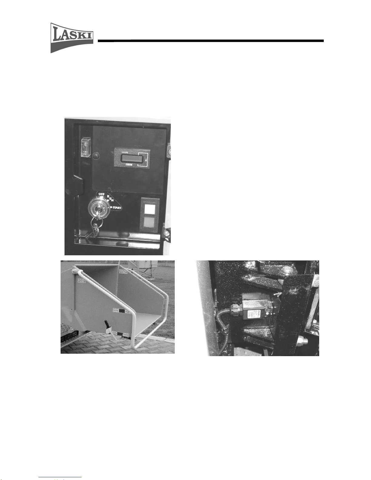
Precautions in Design
This product is equipped with hoods and covers protecting rotary and hot parts
against touching. Protective covers are usually fixed, bolted down on framing.
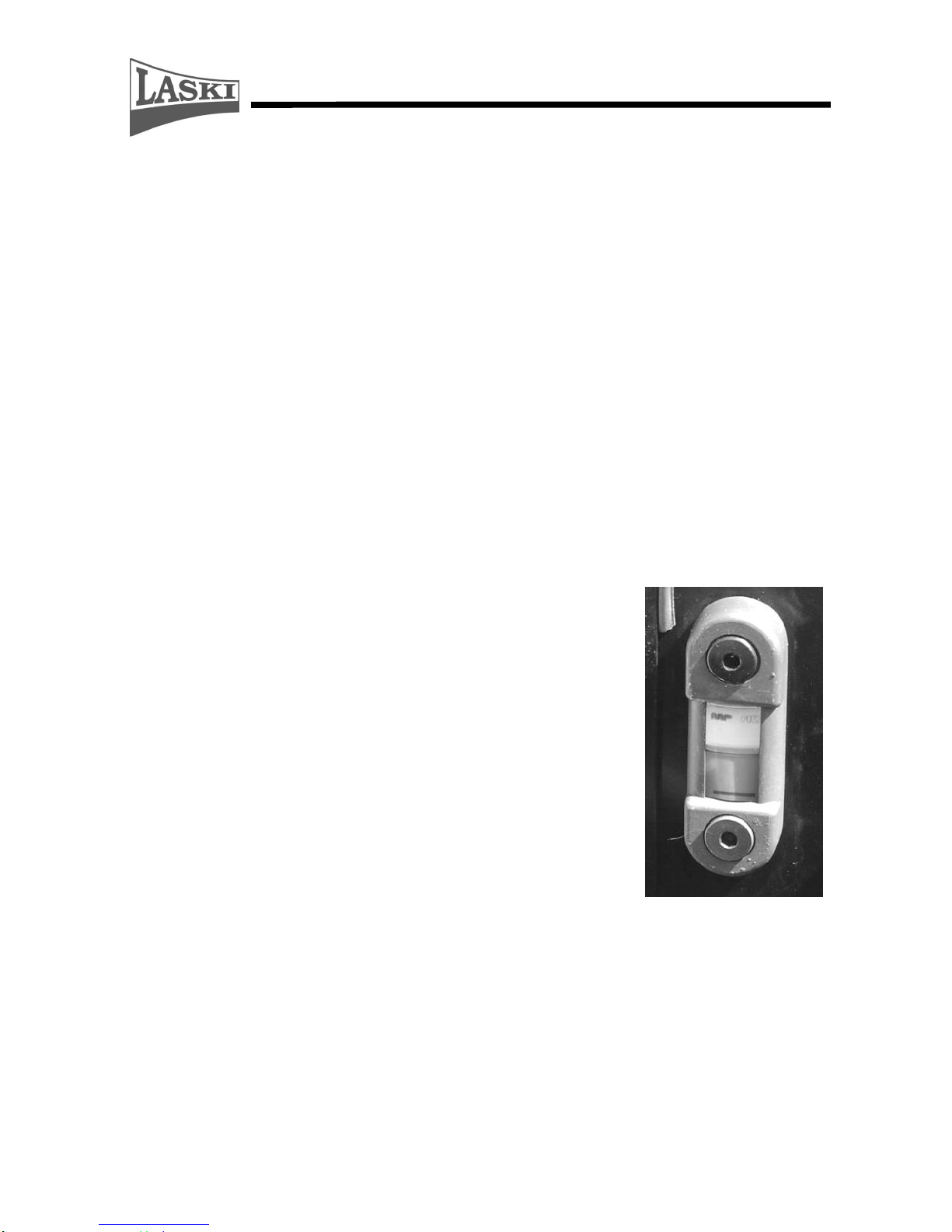
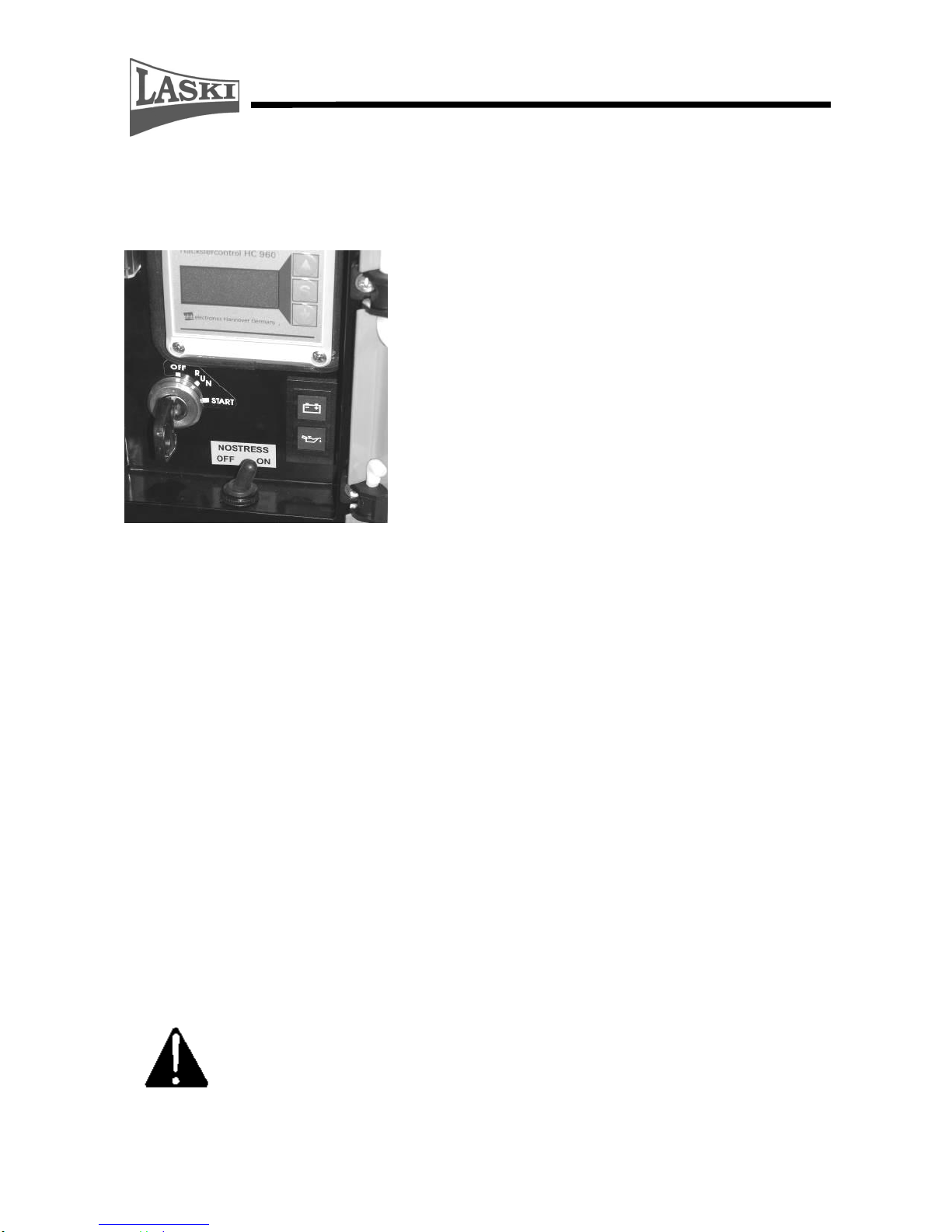
Ignition box for starting, completed
with a removable switch key. Any
confusion with another ignition keys is
not possible. Turn the key in the RUN
position and the orange LED lights on,
i.e. the electric installation of the
machine is in its standby mode being
correctly connected to a towing tractor.
For correct function of the loading rolls
it is necessary to activate the safety
circuit by turning the key in the START
position. The green LED lights up, i.e.
the safety circuit is activated. After any
interruption of the safety circuit it is
necessary to activate it again.
Safety frame for material loading
serves as an actuator for the loading rolls
control, i.e. their stopping or reversing.
Once being pushed the chipper stops
loading motion immediately, the next
pushing brings reverse turning of loading
rolls.
Dangerous space behind the loading
rolls is protected with a hinged cover
and by a terminal switch which blocks
the drive if the cover remains opened.
Once opened the driving hydromotor
stops immediately. This cover is locked
with two bolts that should be properly
tightened.
Page 17
17
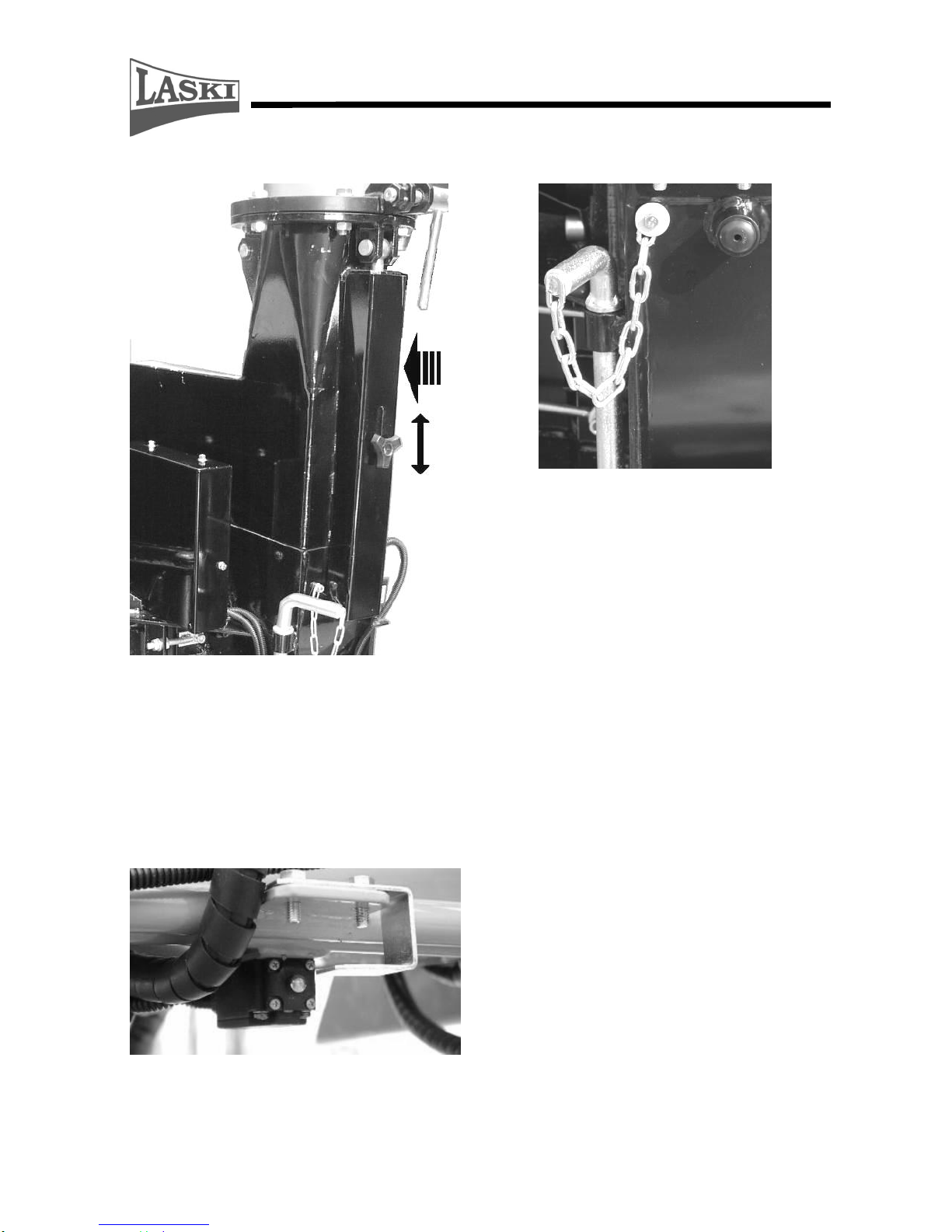
Dangerous space of the chipping wheel
is secured by a terminal switch. To swing
the discharge duck away or to open the
upper half of the chipping wheel guard it
is necessary to unlock the guard and
move it in the arrow direction, see figure.
It is not possible to set the loading rolls
in motion if the guard remains opened.
Safety pin of the chipping device
rotor serves for rotor blocking at
blades exchange and servicing. The pin
is chained on the machine side. A hole
for pin inserting is covered with a
rubber stopper. The chipping device is
blocked if the pin is inserted into a bush
on the rotor.
Terminal switch of a hinged part of the
loading chute turns the driving engine
off if the chute is tilted.
Page 18

18
Emergency STOP button blocks
loading immediately – similar function
as that of the safety frame.
Controls
Ignition box – used for supply and control of the
safety circuit.
CAUTION: Despite the fact that this machine is not
equipped with any driving engine, its ignition key,
analogously to engine starting, must be set in the
START position and afterwards in the RUN position.
The "S" key serves for control of the running hours
counter (daily, total).
Safety frame for material loading with following
positions:
As seen from the attendant's place:
position for MATERIAL LOADING, middle position for
ENERGENCY STOP, by pushing and under
permanent pressure for REVERSE RUN.
This lever controls loading start, stopping and
reversing
Page 19
19
Controller of loading speed - installed under
a hinged part of the loading chute
Change of loading roll speed
Speed regulation in range from 0 to 40 m/min
Emergency STOP button blocks loading
immediately – similar function as that of the
safety frame.
Use
Transport Safety
- For transport the chipper should be coupled to a tractor and locked properly in
its hitch.
- Avoid any side swinging of the chipper and set the lower drawbar tighteners
accordingly.
- Set up the upper drawbar so that the chipper is aligned.
- Plug traffic lights (seven-pole plug socket).
- Checks before drive:
lights
machine for completeness
depositing of cardan shaft (if not coupled)
locking of turnable parts in transport position
depositing and locking of discharge duct
Page 20

20
locking of hinged part of loading chute in transport position
fitting of triangular symbol for slowly vehicles on framing
- It is strictly forbidden to transport the chipper with the PTO shaft on.
- It is not allowed to transport any objects or loads on the chipper.
- Never couple another machine or implement to the chipper.
- Keep side marker lights clean.
- Avoid any damage of side marker lights.
- If necessary, remove all mud and other deposits before coming to a public
road.
- Putting the chipper aside block the tractor against unwilling motion by means
of scotch blocks and mark it as a transport obstacle.
- While going on public roads, keep all traffic rules not to endanger other road
users.
- While working along public roads, keep direction of ejected chips away from
other road users and avoid any road fouling.
- In case of any fault repair the machine always off the road.
- While repairing, avoid any site fouling with oil products, dirty rags etc.
Transport position
Hinged part of loading chute up and locked, discharge duct locked
against turning.
Page 21
21
Storage
Store the chipper always in a dry shelter to protect it against weather effects.
- During storage keep the switch key separately.
- Keep the stored machine beyond unauthorised persons reach.
- Before storage clean all parts of the machine. For cleaning use pressure water.
Should the water be in the chipping device space, wipe it off and let it dry.
- Clean especially oily spots.
- Exchange all damaged or worn parts. Use always original spare parts. For
spare parts contact your dealer or authorised services.
- Do not apply any grease or similar agents on elastic hydraulic hoses.
- Always put the machine aside on a flat and solid floor or on a wooden pallet
for further handling.
- Do not put any objects or tools on the machine.
Before Putting into Operation
- Before the first putting into operation check up the machine for contingent
damages and completeness after its transport and storage.
- Check tightening of bolted joints, especially guards,
grids and completeness of other parts.
- Check movability of turnable parts (loading chute,
discharge duct etc.).
- Check work safety labels for completeness and
legibility. Replace any damaged and illegible label, if
necessary.
- Grease bearings and sliding parts.
- Check the hydraulic oil level (level indicator) and refill
if necessary. The oil level must be between both marks
(MIN and MAX).
- Do not try to repair the machine if it is beyond your
competence. Any servicing, especially of rotating
parts, should be carried out by authorised persons only.
- Check conditions of blades. Replace them if worn or damaged.
- The chipping wheel can be optionally completed with a breaker. According to
the material to be chipped install/remove a breaker on/from the chipping
wheel.
- For replacement use always original spare parts. Parts, such as rotors and
blades, must be balanced properly.
- All blades should be replaced always at the same time as a set. Pay special
attention to their fixing bolts. Replace them if worn or damaged.
Page 22
22
- Avoid spillage at filling hydraulic oil. Use always a proper filling funnel. If
any oil is spilled or overflowed then wipe off the spots immediately.
- Do not use petrol or similar inflammable matters as a cleaning agent.
- It is strictly forbidden to do any technical changes on the machine without any
prior approval of the manufacturer in writing.
- If any adjustment is required, do it always at standstill only. Remember
blocking the wheels against unwilling motion.
- Check conditions and proper tightening of V-belts.
- It is strictly forbidden to start the chipper with removed hoods and guards.
This chipper can be optionally equipped with an optional breaker which is to be
installed close to the blade output opening in order to break transversely cut wood
slices. It is not included in a standard delivery.
RECOMMENDATION:
The breaker should not be used for small and short wooden pieces, leaved or
coniferous branch wood (with low weight) which may bring fouling due to
shortage of woody mass. To clean the fouled ducting just put some more woody
materials inside the loading chute.
Page 23
23
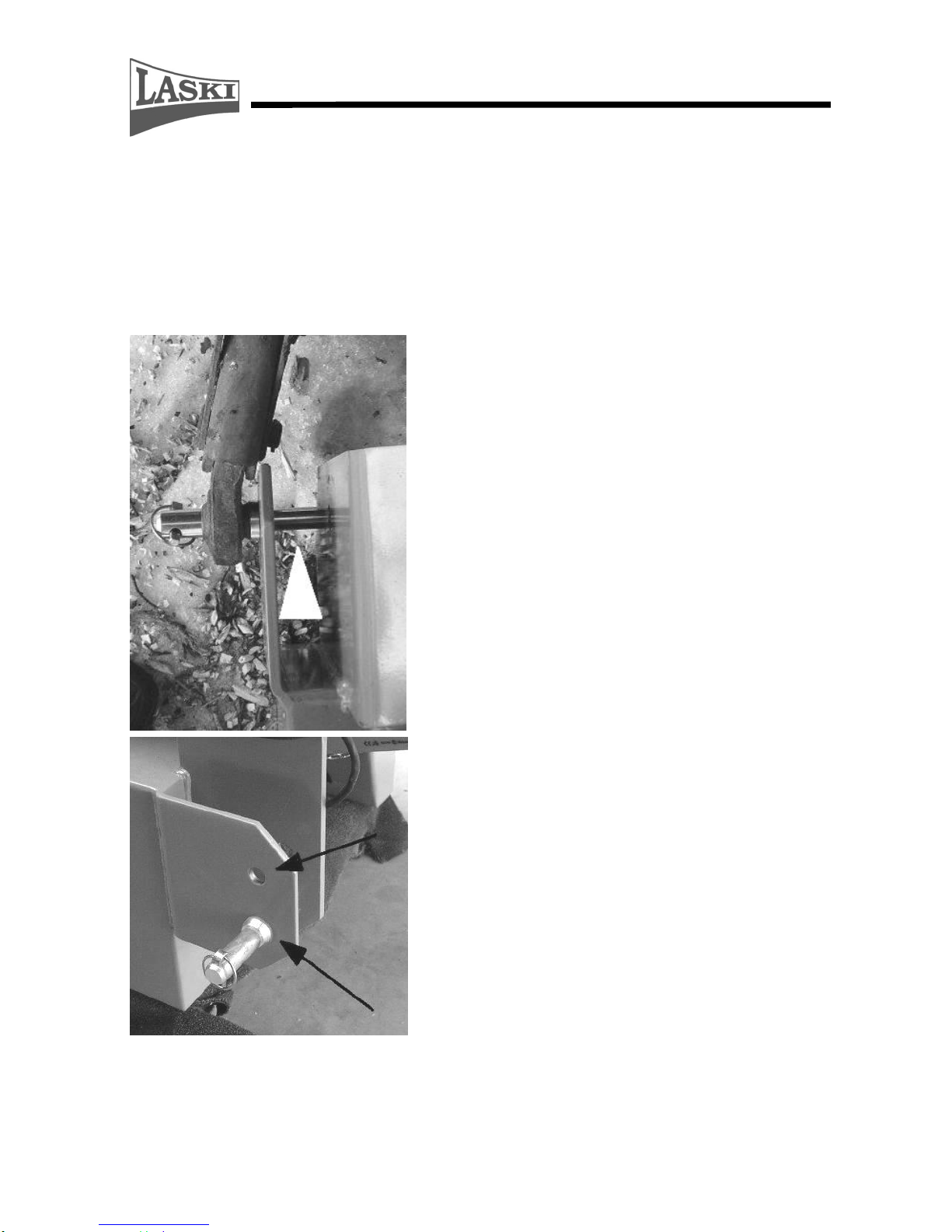
Coupling to Tractors
This chipper can be coupled to a tractor which is equipped with a three-point hitch,
category I or II and a PTO shaft. This hitch coupling can be done from outside by
means of locking pins, Ø 27 mm for the category II or Ø 22 mm for the category I.
The chipper is height-adjustable (according to tractor tires size) when inserting
pins in other holes, see following figure.
The lower drawbar of the three-point
hitch can be coupled to a pin Ø 27 mm
from outside. The white arrow shows
a coupling point where the lower
drawbar is to be hinged. In both cases
the locking pin must be properly
locked.
Height adjustment by means of a hinge
pin
Page 24
24
When coupling the chipper to a tractor just let the lower drawbars go down in a
similar height as the coupling pins are. Go back slowly with the tractor to the
chipper hinge.
While coupling the chipper no person is allowed to stand between the
chipper and the tractor
Lock the lower drawbars by means of locking pins in the chipper
hinge. Make sure that the pins/drawbars are locked properly.
Connect power supply by means of a plug and a socket used for a service lamp
Putting into Operation
Before start check if the loading chute and the discharge duct are free of
any materials. Direct the discharge duct out of possible motion of other
persons or prevent other persons to enter the working area. At work
proceed always very carefully.
- Let the three-point hitch go down on the ground.
- Swing away the hinged part of the loading chute and lock it.
- Swing away the discharge duct and lock it by a locking nut.
- Set the guard under the discharge duct in the upper position and lock it by a
locking nut.
- Set the safety lever in the central STOP position to block the loading rolls.
- Close all guards (if opened).
- Turn the PTO shaft on and let it running at slightly increased speed, as rated
for 540 rpm shaft speeds.
As soon as the PTO shaft starts turning, the chipping wheel and V-belts
are set in motion. Keep away from these rotating parts.
- Set the control lever in the position for LOADING.
- Set the switch key in the START position and then release the key in the
position for RUN. Now the loading rolls start turning.
- Having turned the chipping device on wait for speed stabilization. With that
you may soever increase or reduce the tractor PTO shaft speed.
- CAUTION !!! As soon as the PTO shaft is ON, the tractor hydraulic
circuit is under pressure and the loading rolls start turning according to
actual setting of the safety frame or of the control lever.
- CAUTION !!! As soon as the PTO shaft is ON then chips from previous
operation may be ejected from the discharge duct.
Page 25
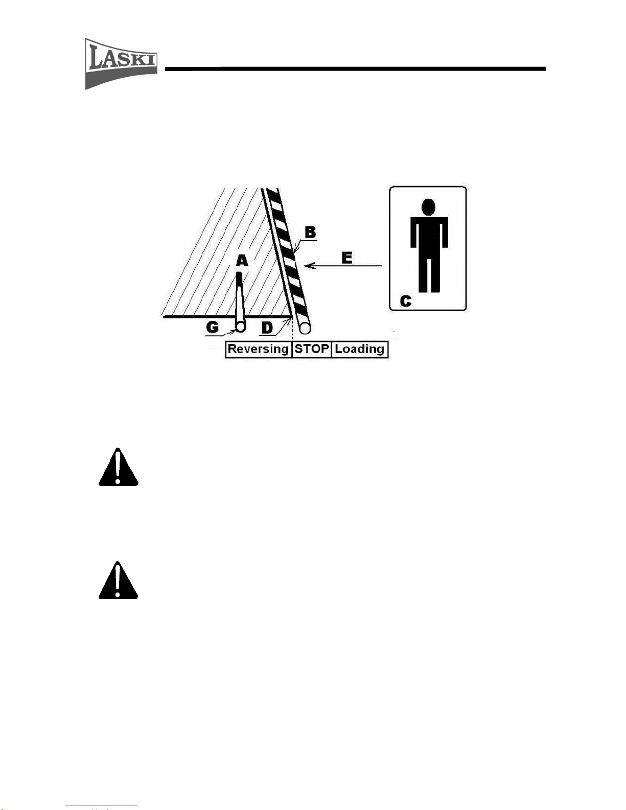
25
- Carry out a functional check of the safety frame of the loading chute. Set the
lever in the infeed position and the loading rolls start turning (loading). By
first pushing the frame the rolls should stop loading immediately
(EMERGENCY STOP), the next pushing behind the chute edge (D) brings
their reverse turning.
Legend:
A - loading chute, B - safety frame, C - attendant's place, D - loading chute edge,
E - infeed direction, G - control lever
- The safety frame must be always adjusted so that the
EMERGENCY STOP must be activated before the point D –
loading chute edge.
- Do not leave the machine unattended.
Chipping
- The chipper is powered by a tractor combustion engine. Do not
start it in confined or ill-ventilated spaces or under conditions of
low visibility.
- While chipping the chipper must always be properly coupled to a
tractor.
- It is not allowed to use the cardan shaft with its damaged guard. This guard
must be properly locked against turning. Check up locks on the sliding shaft.
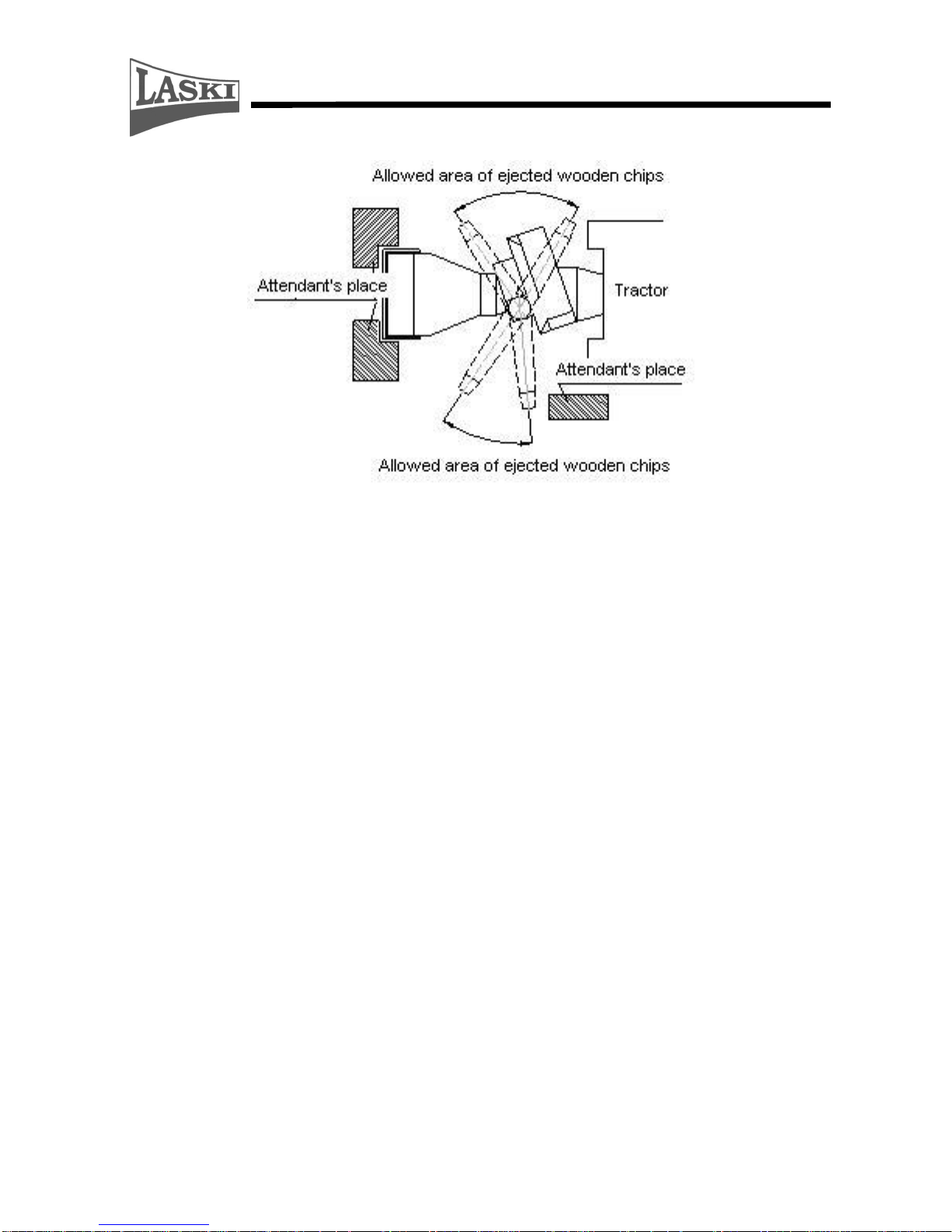
- Set the discharge duct in required direction. The discharge duct cannot be
directed to the attendant's place, see following figure.
Page 26

26
- When loading materials and during operation of the chipper the attendant
should always stand in the attendant's place, see fig.
- Having turned the chipping device on wait for speed stabilization. With that
you may soever increase or reduce the tractor PTO shaft speed. For correct
chipping functions it is necessary if the tractor PTO shaft speed is 540
rpm(1000 rpm).
- Wooden chips can be gathered in bulk or into a container located on a towing
vehicle.
- While discharging into a container, pay your attention to ejecting to avoid
ejecting chips back out off the container.
- Before going to another working place it is necessary to turn the PTO shaft off
and wait for total stopping of the cardan shaft. Before going lift up the chipper
above the ground by means of the three-point hitch and tractor hydraulics.
- Do not load materials with parts of metal, glass, ceramics and other similar
objects.
- Do not chip or load materials while driving.
- Having put materials in the loading chute/between loading rolls, release the
loaded material immediately and keep a certain distance from the chute.
- When working, never lean over the loading chute and never pull out wooden
materials, already loaded, from the chute.
- Do not load materials with diameters exceeding 150 mm.
- If loaded materials are spreading with risks of catch holding of attendant's
dress being drawn in the loading chute then it is necessary to prepare such
materials accordingly (trimming, cutting).
- Pay special attention to thorny materials, such as acacia and roses, which may
easily catch your sleeves.
Page 27

27
- Be careful while loading since materials may unexpectedly move in unwished
directions.
- In case of two attendants it is necessary to make simple signals clear before
working. During operation it is not easy to make any agreements because of
operating noise.
- Observe the working area. If any person, children or animals approach while
chipping, then stop working immediately.
- Be aware that there is a certain time period required between loading, chipping
and final ejection of chips.
- As far as possible load the chipper evenly, adapt loading speed accordingly
and keep continuous chipping.
- While loading, stand aside the loading chute.
- When loading short materials, throw them in the chute and push them forward
between the loading rolls by means of a wooden rod or another branch.
- Never use metal objects. They could cause serious damage of the loading rolls
and blades.
- When finishing the work, first wait for emptying of the loading chute.
- Lengths of materials to be loaded should not exceed 3 meters.
Recommendations:
Do chipping at rated PTO shaft speed only, i.e. at
sufficient power of the chipping wheel for ejecting chips.
Being loaded short and fine materials may deposit or clog
the space behind the loading rolls in front of the chipping
wheel. To avoid such problems and clogging put
occasionally also some longer branches.
To prolong service life of blades never put any materials
with parts of impurities, such as of metal, glass, ceramics
and other similar objects.
Optimal sharp blades reduce operating costs of the
loading and chipping equipment (reduced wear of the
chipping device).
If loaded material is free of any impurities then a grinding
interval for blades may last several months or several
hundreds m3 of loaded materials.
Page 28

28
Blunt blades are evident on chipped edges which are not
clean but broken.
The optionally used breaker for crushing brings increased
costs for energy consumption.
The breaker should not be used for small and short
wooden pieces, leaved or coniferous branch wood (with
low weight) which may bring fouling due to shortage of
woody mass.
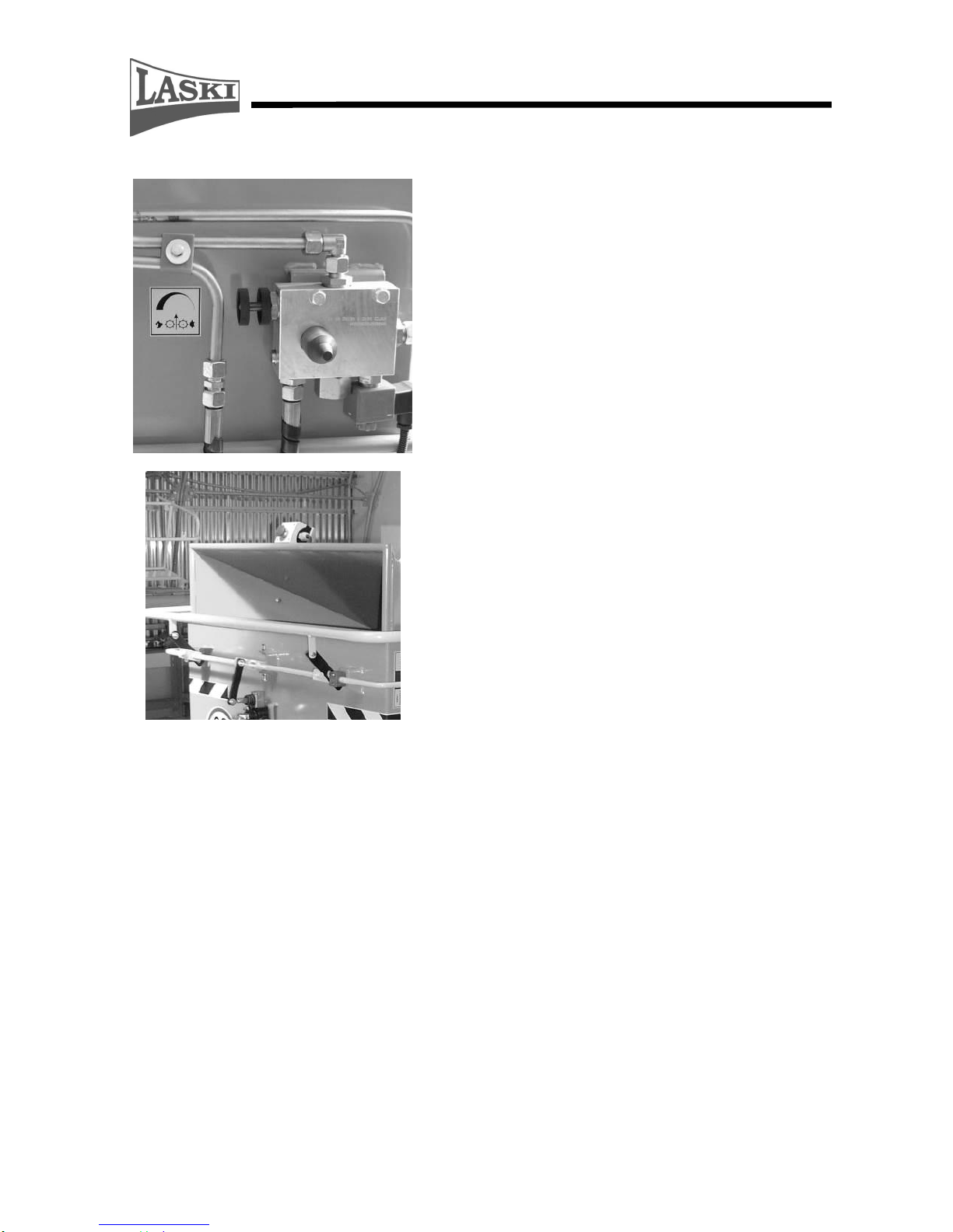
The chipper is optionally equipped with its speed regulation and the NOSTRESS
system intended particularly for tractors with power less than 30 HP.
This regulator reduces material feeding upon contingent overloading (PTO shaft
speed dropping).
The chipping wheel speed is set by the manufacturer to 1450 rpm to turn the rolls
off and to 1500 rpm to turn the rolls on again.
Recommendations!!
Should the loading rolls be frequently turned off while chipping,
it means that there is too much material loaded and the chipping
device is overloaded. To avoid this overloading:
reduce volume of material to be loaded, or
reduce infeed speed of the loading rolls
The loading rolls infeed speed can be reduced by the regulating screw (see arrow
on following figure) under the hinged part of the loading chute. To change the
infeed speed, just turn the regulating screw accordingly.
Page 29

29
Putting out of Operation
If you want to stop chipping:
- In case of loaded material wait for emptying of the loading chute.
- Wait for emptying of the discharge duct.
- Turn the tractor PTO shaft off.
Warning! The cardan shaft is equipped with a freewheel clutch. When
turned off, the rotor of the chipping device runs out – approximately 120
sec.
- Regardless of this running out, turn the switch key in the STOP position.
Emergency Situations
Put the chipper out of operation immediately in
following cases:
- If any person or animal approaches under 20 m while chipping, then stop
working immediately.
- If any breakage, damage or disengagement occurs, stop chipping immediately.
- If you heard any strange noise or vibrations or felt a strange smell while
chipping, then turn off the machine immediately and contact your dealer or
directly the manufacturer.
- In case of fire or breakdown, stop chipping immediately.
- In case of fire use foam extinguishers only.
- If you cannot damp the fire down yourself, call for a fire brigade.
- If an attending person gets caught by rotating parts or loaded materials, stop
the loading rolls by pushing the safety frame (STOP position). Stop working
and go on only if the attending person is uninjured and fully concentrated.
- If the discharge duct gets clogged, stop loading immediately and reverse the
loading rolls by pushing the control lever in the REVERSE position. Turn the
PTO shaft off and while having all rotary parts stopped (after about 120 sec)
use an elastic rod and try to release the clogged material in the end piece of the
discharge duct. Having released the clogged material, try to turn on the PTO
shaft again. If it is not successful, remove the upper hood part and try to
remove all materials by hand (the chipping wheel must be blocked properly
while removing materials).
Page 30

30
Technical Description
This machine consists of following main parts:
- chipping device
- loading chute
- loading rolls
- chipping wheel
- discharge duct
- frame
Chipping Device
Loading chute
The loading chute is made of welded steel plates consisting of two parts: fixed
and hinged one. The hinged part serves as an extension of the chute with a safety
frame and is protected by a terminal switch. This frame, if pushed by an attending
person or branchy materials being caught, turns the loading rolls off. The chute
itself, shaped as a square pyramid, is decreased in width toward the loading rolls
and in this way loaded materials are pressed together.
Loading rolls
These rolls take over loaded materials and move them to the chipping wheel. Their
speed can be regulated according to the given sort of material and expected results
– chips. The top roll is ribbed and the bottom one smooth. These rolls enable
loading materials and also pulling them out at reverse turning, if necessary
(chipping wheel overloading). The top roll is height-adjustable according to the
given material. The rolls are powered by a hydraulic motor. This infeed device is
equipped also with speed regulation based on chipping wheel speed sensing. Its
evaluation and following switching is controlled by a logical unit in the driving
part.
Chipping wheel
It is a steel disc serving also as a flywheel for absorption of shocks while chipping.
This wheel is put in ball bearings; a drive pulley is fitted on its shaft. The wheel is
equipped with two blades for cutting of loaded materials. Vanes welded on its rear
side serve for ejecting chips in the discharge duct. This chipping wheel can be
optionally completed with a breaker which is to be installed close to the blade
output opening in order to break transversely cut wood slices, e.g. for further
mechanical processing or heating.
Page 31

31
The chipping wheel is installed in a rigid frame and protected by a steel plate. Its
protective shield consists of two parts and particular parts are bolted together. By
safety reasons the upper part is protected with a terminal switch for turning the
drive off if the shield was opened or got loose.
Discharge duct
This duct continuously extends the chipping wheel shielding and serves for
directing the ejected chips. The duct is turnable and its end piece (tilting gate)
serves also for setting the range of ejected chips.
Frame
This rigid frame is equipped with three-point hitching for coupling to a tractor.
In the lower part of the frame there is a gearbox with an input shaft. The chipper
itself is fitted on a swivel base.
Technical Parameters
Parameter
Unit
Value
Overall length/transport length
mm
2535/2135
Overall width/transport width
mm
1495/1490
Overall height/transport height
mm
2735/2025
Weight
kg
780
Chipping device:
Chipping wheel – diameter
mm
560
- number of blades
-
2
- number of breakers
-
2
- rate of cutting
m.s
-1
42
Max diameter disposed materials
mm 160
Chipping wheel drive
-
3 x belts B 17 x 1422 La
Loading device:
Infeed hole size
mm
290 x 220
Number of loading rolls
-
2
Diameter of rolls
mm
190
Feeding speed
m.s-1
12 - 40
Drive
-
hydrostatic
Loading roll speed for turning-off
min
-1
1525
Loading roll speed for turning-on
min-1
1550
Speed regulation
-
NOSTRESS
Loading chute:
Feeding profile
mm
920 x 800
Drive:
Type
-
tractor PTO shaft
PTO shaft speed
min-1
540 (1000)
Shaft - six-spline
Hydraulic oil:
-
OH HV 46
Page 32
32
ISO VG 46, ISO 6743/4 typ HV
CETOP RP 91 H Category HV
DIN 51 524 část 3-HVLP
Poclain P00552-13P
Capacity of hydraulic oil tank:
l
15
Gear Oil -
SAE 80W/90, API GL-4
Recommended amount of gearbox
l
1,5 + 1,5
Maintenance
- Any servicing of the chipper should be carried out by authorised
persons only.
- Check up the machine for completeness and its general condition.
- Any maintenance and servicing on the machine can be done at standstill only,
i.e. the PTO shaft off, the switch key being pulled out from the ignition box,
tractor wheels blocked against unwished motion.
- While servicing the chipper should be lowered on the ground.
- Pay special attention to all safety elements.
- Check up V-belts for tightness and wear.
- Keep regular intervals for lubrication of bearings.
- Check up condition of blades and chipping wheel vanes regularly.
- Check up hydraulic hoses for wear. Replace them if necessary or every five
years.
Lubrication
Grease cups of chipping wheel
Lubrication every 40 running hrs
(LTA 3EP MOL Lition)
Grease cups of loading rolls
Lubrication every 40 running hrs
(LTA 3EP MOL Lition)
Page 33
33
Grease cups of loading roll slides
(LTA 3EP MOL Lition)
Grease cups of swivel base
(LTA 3EP MOL Lition)
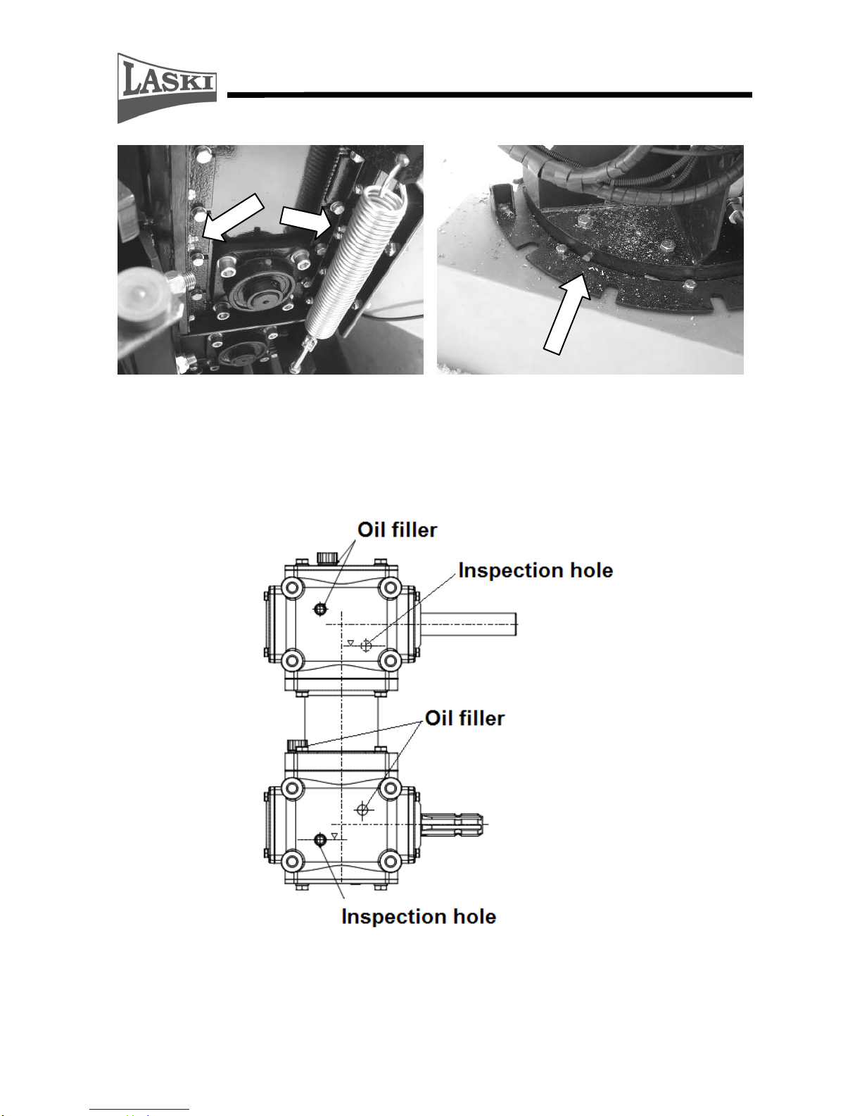
Oil change in gearboxes
Gearbox oil - SAE 80W/90, API GL-4
Oil charge – 1,5l per 1 gearbox, in total 3l oil
Oil change after 2500 working hours or 5 years
Page 34
34
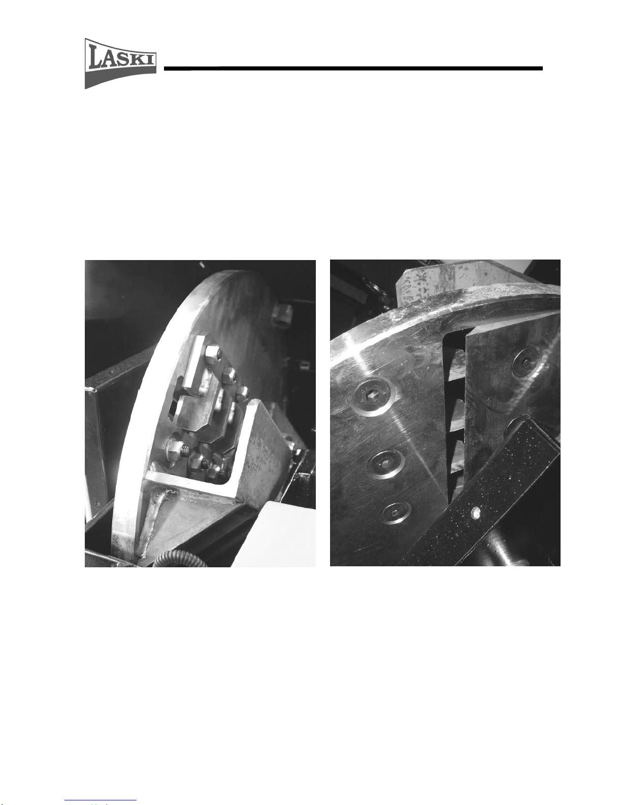
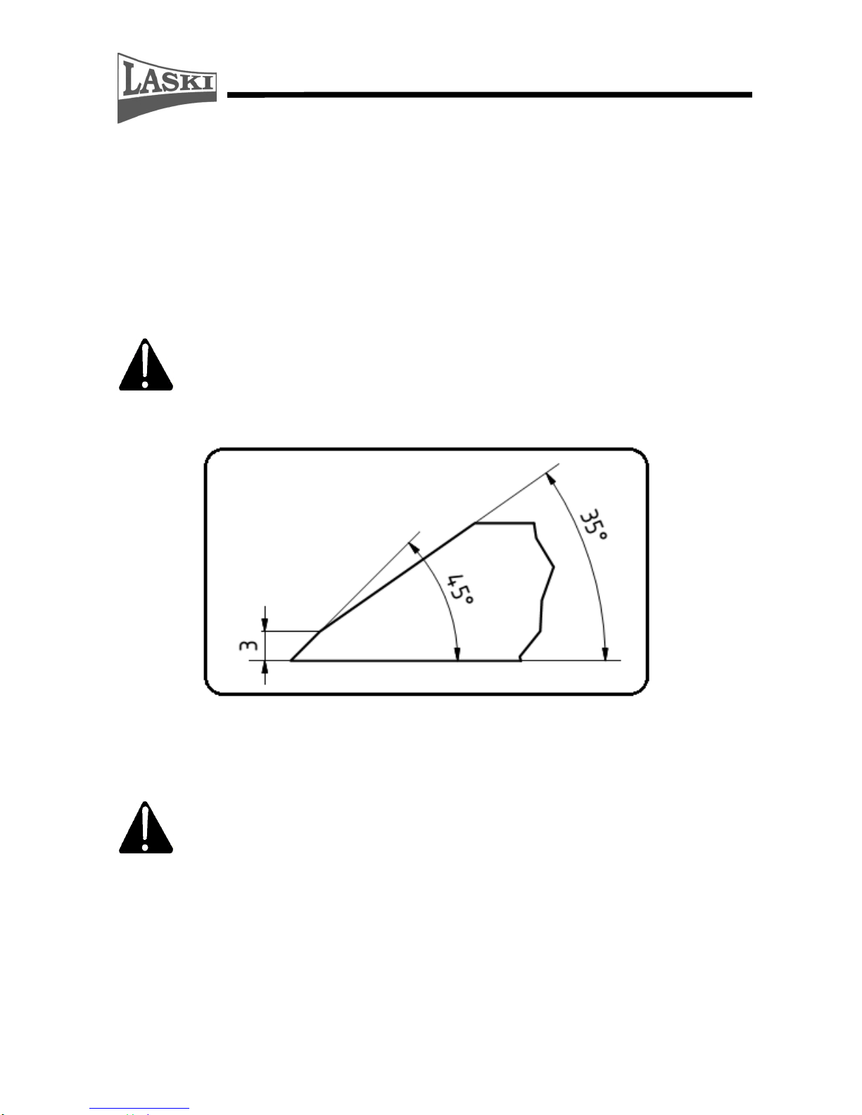
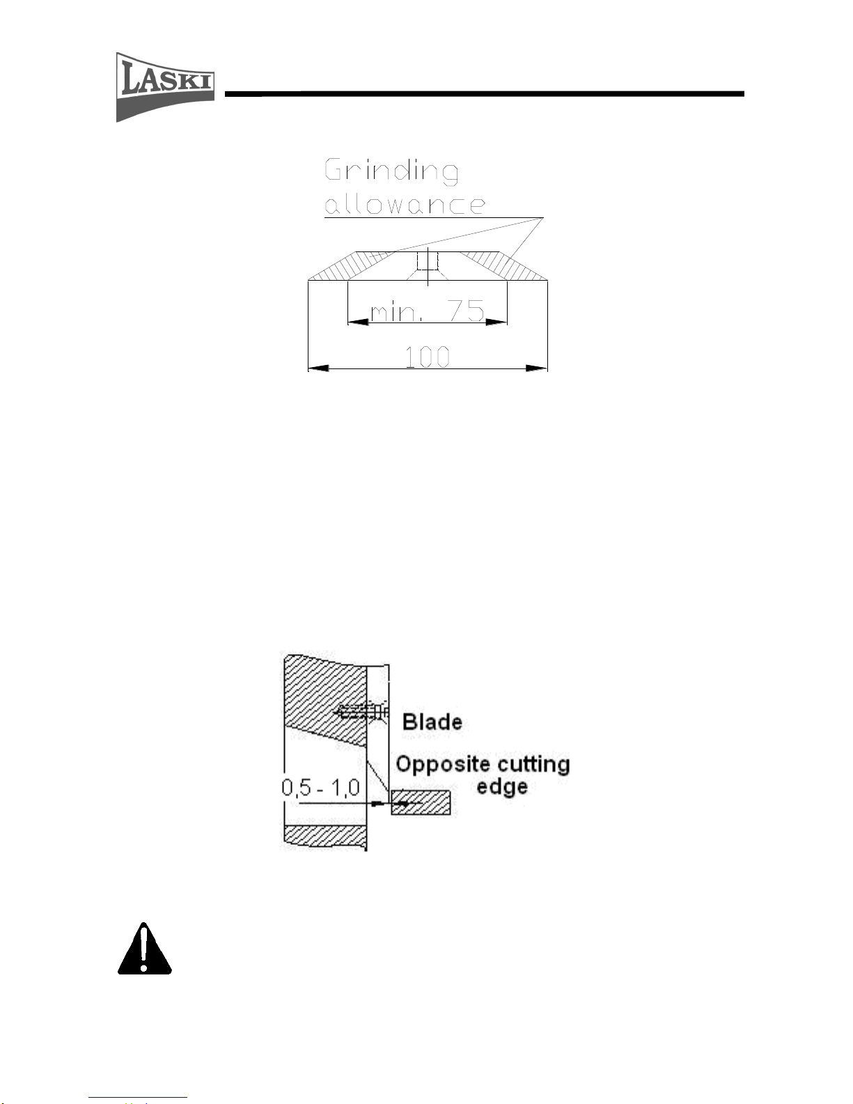
Blade Grinding
Blades, fitted on the chipping wheel, are double-sided, i.e. reversible if one side is
blunt.
Blades edge regrinding requires high demands for keeping cutting edge shape.
While grinding it is necessary to keep its optimal geometry, see following figure.
Proper shapes prolong blade service life.
While regrinding it is necessary to keep the same weight of particular
blades because of balance of their rotating mass. For grinding use
always a grinder with its magnetic table and a special jig.
Detailed geometry of blade edge
Grind every blade only up to minimum distance from edge to its fixing
bolt. i.e. 37,5 mm. This distance on a new blade is 100 mm, see
following figure.
Page 35
35
Max. wear/grinding of cutting edge
Chipping Adjustment
Optimal operation of the chipping device requires proper setting of a clearance
between the blade and the opposite cutting edge. This distance should be set (see
following figure) and checked after fitting ground blades, then it grows with their
wear and chipped branches may be squeezed between the blade and the opposite
edge. It brings deterioration in quality of chipping.
Pay attention also to blades exchange. In such case set the given clearance bigger
to avoid damage of a new blade and its opposite cutting edge.
Recommendation: Check out conditions of blades every 40 operating hours.
Regrind blade edges if they are found blunt
Jointing elements (bolts and nuts) should be replaced together with
The blades exchange. Safety nuts should be used only once, since they
lose their self-locking properties if used repeatedly. The fixing bolts
should be tightened with torque of 100 Nm.
Page 36
36
NOSTRESS System – Speed Regulation
This system is intended for overload protection of
the combustion engine consisting of an electronic
control unit and a speed sensor installed on the
rotor shaft
No Stress ON – the machine chipping with
automatic regulation the infeed of the material (
there is no overload of the combustion engine
consisting)
No Stress OFF – this one use only when the No
Stress control unit is fail so that the Chipper does
without automatic regulation the infeed of the
materiál.
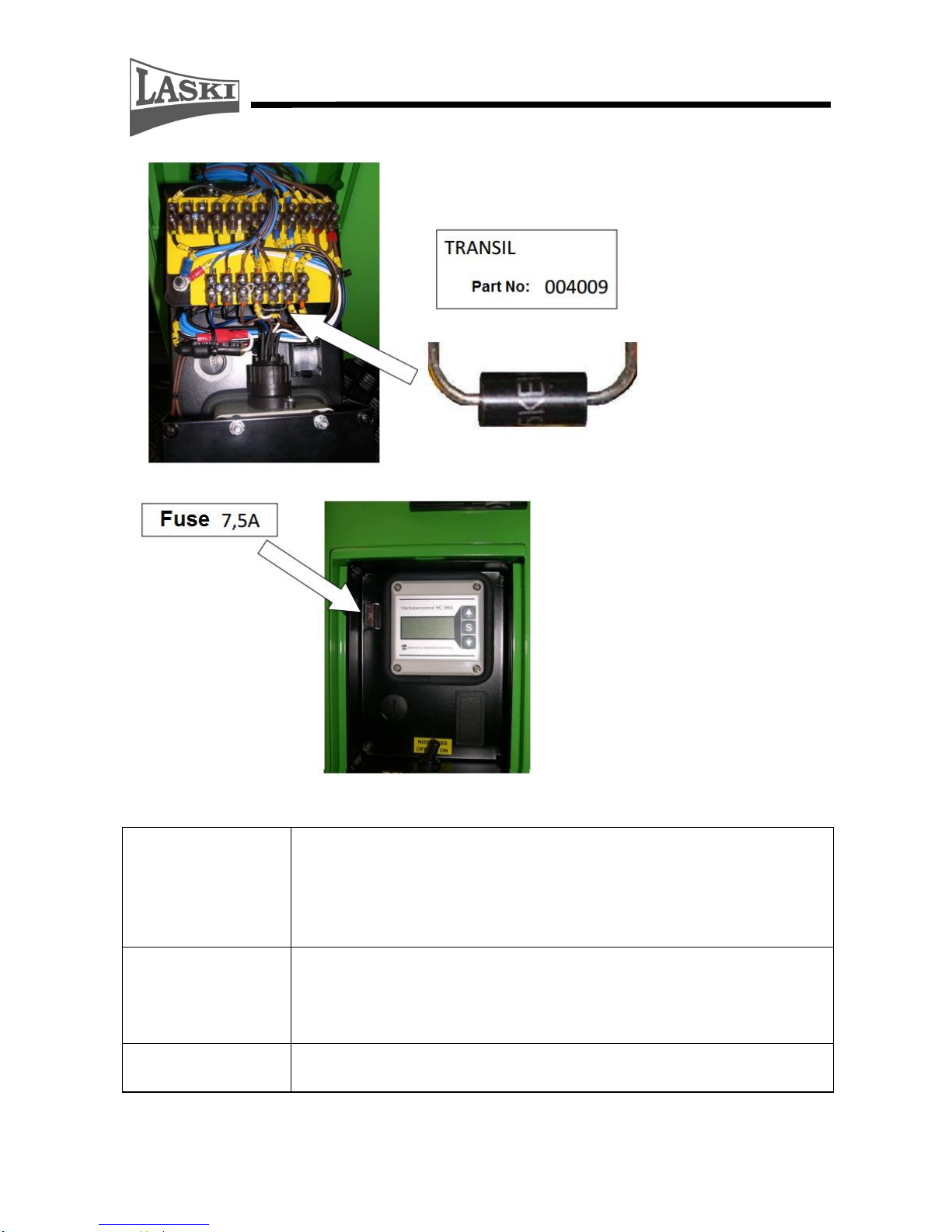
Control unit:
This control unit displays actual rotor speed values. When the rotor stops, the unit
displays a total number of running hours "th". To display a daily number of
running hours, just press the button "S". To reset this daily number, just press the
button "S" once to display a total number of running hours "th" and then press it
again and hold for total resetting. This control unit is protected by two fuses: 7,5 A
– installed just by the unit and 4 A – installed inside.
Right function of NOSTRESS system
This speed regulator reduces material feeding upon contingent overloading. The
chipping wheel speed is set by the manufacturer to 1525 rpm to turn the loading
rolls off and to 1550 rpm to turn the rolls on again. Actual rotor speed values are
displayed on the control unit.
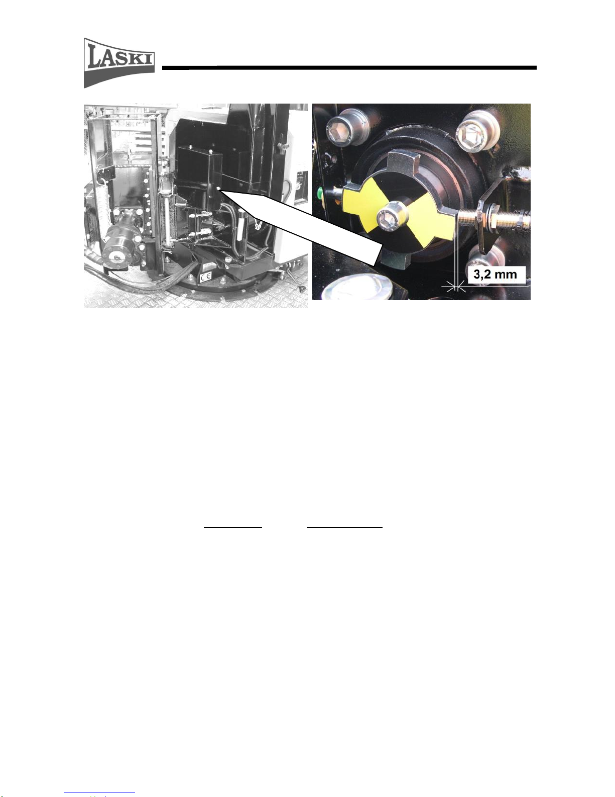
Speed sensor:
This encapsulated sensor in fitted on a holder in a distance of 3,2 mm from the cam
lobe. In the rear part of the sensor sleeve there is an orange LED installed which
should be flashing in case of proper sensing.
The own setup (respectively check-up) of the speed sensor should
be done at standstill only.
Page 37
37
Location of sensor under hood
NOSTRESS system protection against overvoltage
Overvoltage occurrence in the electric installation blows the fuse and breaks the
TVS diode (Transient Voltage Suppressor / Transil) used to protect
sensitive NOSTRESS electronics against voltage spikes. Should the fuse (7,5 A) be
blown again, first replace the damaged TVS diode and then put a new fuse.
Page 38
38
Maintenance Intervals
Electric
Installation
Protect all wires against contact with oil products. Keep all
elements clean and avoid any damage of wires - short circuit
risk. All connections must have clean and proper contact
surfaces to avoid intermediate resistance at a wrong contact
point.
Hydraulic Oil
Change
Do the first oil change after the first 500 running hours or after
the first season. Next oil changes always after 1000 running
hours. It is recommended changing the filter element together
with the oil change.
Hydraulic Oil
Filter Change
We recommend changing the filter element together with the
oil change.
Page 39

39
Checking, Oil Exchange
Operation
Component
Interval (hrs)
10
100
250
500
1000
2500
5000
Cleaning
Hydraulic oil tank
*
Hydraulic oil filter
*
Checking
Hydraulic oil in tank
*
Exchange
Hydraulic oil in circuit
*
Exchange
Oil gear
*
(5
years)
(*) clean daily under special conditions
(**) clean every 4 – 5 hrs under extreme dusty conditions
(***) see recommended oils
(o) if clogging indicated
() first exchange
Failures and Troubleshooting
Failure
Cause
Remedy
Wrong chipping
or loading
Blunt blades
Remove and regrind blades. If worn,
replace them for new ones.
Worn opposite cutting
edge
Remove and regrind cutting edge; set
optimal clearance between blade and
opposite cutting edge
Malfunction of loading
rolls
See Problems with hydraulics
Wrong angle geometry
Regrind in accordance with detailed
figure of edge geometry
Damage/wear of
loading rolls
Replacement
Too small, dry or rotten
materials
Mix before loading
Breaker fouled
Load longer materials with higher
weight
Loading rolls do not
turn – rotor runs idle
Wrong setup of sensor for turning the
loading rolls on
service
Tractor engine
overloaded while
chipping
Wrong sensor setting
for min. speed
Switching-off speed is set too high
service
Blown fuse in
regulation circuit
Fuse replacement
Faulty control unit in
regulation circuit
Replacement
Faulty sensor – LED
does not burn
Replacement
Loading rolls do not
turn
Faulty electric
switchboard
Coil replacement
Page 40

40
Throttle valve closed
Check up manual speed regulation for
loading
Control lever in wrong
position
Press the lever in loading direction
Failure of NOSTRESS
system
Measure voltage on coil of
electromagnetic valve; it should be 0
at max. speed
Faulty coil of
electromagnetic valve
Coil replacement
Broken leads
Check up wiring for integrity
Faulty hydraulic pump
Pump replacement
Safety circuit not closed
Tilt rear part of the loading chute and
check up hood position protected with
terminal switch
Blades touch opposite
edge
Wrong setting of
clearance
Set distance to 0,5 – 1 mm
Loosen blade bolts
Tighten up fixing bolts
Clearance of chipping
wheel bearings
Tighten up fixing bolt of wheel on its
shaft
NOSTRESS system
out
of function
Blown fuse
Replacement of fuse 7,5 A
Faulty electronic
control unit
Replacement of fuse 4 A (inside
control unit)
Vibrations on discharge
ducting
Control unit replacement
Faulty speed sensor –
LED is not flashing
Check up wiring
Loading chute gets
clogged
Sensor replacement
Discharge duct gets
clogged
Too low speed of PTO
shaft
Stop loading and increase speed at
chipping. Min. working speed of PTO
shaft at chipping is 350 rpm
Discharge duct
deformed
Repair/replacement
Too small, dry or rotten
materials
Mix before loading
Loading rolls
overloaded with
material
Reduce loading roll speed
Bearings overheated
Insufficient lubrication
or wrong lubricant used
Lubrication and lubricants should be in
accordance with recommended
intervals and sorts (LTA 3EP MOL
Lition)
Too high speed of
chipping wheel
Optimal speed should not exceed 1900
rpm (PTO shaft: 620 rpm)
Page 41

41
Bearing loosened
Tighten up bearing housing bolts with
required torque
Bearing worn
Replacement
Waste Disposal
Any waste materials resulting from the machine operation should be disposed
in accordance with laws and regulations applicable in the given country.
Protect nature and water resources against used oil and filter elements.
Any parts of the machine should be disposed in accordance with laws and
regulations applicable in the given country.
Use of the chipper equipped with a hitch
The tractor-mounted chippers LS 150T can be optionally equipped also with a
hitch for towing of a trailer during chipping.
The hitch, mounted on the chipper rear, is intended solely for towing of a trailer
during chipping, i.e. for gathering of ejected wooden chips. It is forbidden to
couple a trailer to the chipper for its transport on public roads. This restriction can
be found also on a safety plate on the chipper.
Usage of a trailer coupled to the chipper can reduce running costs at chipping. It is
possible to displace the chipper to another site on short distances by means of one
towing tractor only, instead of two. The second tractor can be used only for
bringing of an empty trailer and removal of a loaded trailer.
For coupling of a trailer and its safety handling our chippers can be optionally
equipped with the hitch Rockinger, type 810B30, homologation
E1*89/173*2000/1*0296**00.
Besides the hitch on the machine rear there are also air-brake couplers for trailers
with two-line braking systems installed here: the red one as a filling line and the
yellow one as a control line. Both lines of the trailer braking system are to be
coupled through air hoses to the same couplers on the tractor rear.
On the machine rear there is also a 7-pin receptacle installed for the trailer lights
which should be interconnected through the corresponding plug on the machine
with the 7-pin receptacle on the tractor rear.
Page 42

42
Conditions for use of the hitch for towing of a trailer during chipping
1. The hitch, mounted on the chipper rear, is intended solely for towing of a
trailer during chipping, i.e. for gathering of ejected wooden chips.
2. It is forbidden to couple a trailer to the chipper for transport on public roads
3. While working on or nearby public roads the towing tractor must be equipped
with a beacon of orange colour for flashing and the chipper must be equipped
with 2 safety plates with red-white hatching, sight lights, reflector glasses and
a warning triangle for marking of slow-moving vehicles. The beacon on the
tractor cab must be turned on.
4. All the given lights, glasses and plates must be approved for transport on
public roads complying with applicable EU standards and local regulations. Be
aware that traffic rules and regulations in different countries may differ.
5. Max. permissible trailer gross weight is 8 000 kg.
6. Max. permissible vertical coupling load is 50 kg.
Page 43

43
7. Due to low permissible vertical coupling load it is forbidden to couple trailers,
resp. semi-trailers, with axles centrally mounted.
8. The trailer to be coupled must be in good technical condition and its brakes,
tyres and lights must by fully functional. The trailer must comply with
applicable EU standards and local regulations.
9. Min. drawbar length of the trailer must comply with legal requirements
applicable for tractor trailers. In case of doubts this length is to be checked
before the first use: the drawbar must not collide with the chipper in any
working position of the chipper or trailer.
10. While coupling, you must always interconnect both air-brake couplers and the
7-pin plug of the trailer with the tractor.
11. While chipping, the chipper should rest on the ground, the entire train must be
braked mechanically or blocked by means of scotch blocks. At work on hilly
terrain the trailer must be braked by means of its parking brake and in addition
to that its wheels must be blocked by scotch blocks.
12. The attendant is obliged to check efficiency of the braking system of the entire
train.
13. Set the loading chute so that it is accessible in any position of the coupled
trailer for material loading. When using a coupled trailer, you should direct the
discharge duct and its end piece to allow safe gathering of ejected chips in its
loading space.
14. While chipping in the vicinity of a road-side ditch or close to a terrain slope,
pay special attention to undulations of the ground to avoid any risk of slipping
or falling.
15. For displacement of the chipper to another site on short distances it is
necessary to set the loading chute in the tractor axis, to lift up the chipper
about 25 to 30 cm above the ground and to release the trailer brakes
respectively to remove the scotch blocks. For this displacement the trailer
Page 44

44
brakes and lights must be fully functional and the chipper engine must be
turned off.
16. If the chipper works in the same workplace for a longer time, it is necessary,
before its displacement, to check out safe coupling of the trailer, its air-brake
couplers and electric plug and to test their functionality.
17. At public road transport the tractor driver must keep all local regulations valid
for public roads. It is not allowed to exceed max. permissible speed of the
tractor or of the trailer.
18. Always before work with the trailer it is necessary to make checks of the hitch,
safe trailer coupling, interconnection of the tractor/trailer braking and
lightning systems and to keep them in proper technical condition.
Warranty
The manufacturer provides warranty on this product for a period as stated in the
enclosed Warranty Certificate. The given warranty period begins after delivery to
the customer.
This warranty covers all failures resulted from faulty assembly, manufacture and
used materials.
The manufacturer bears no responsibility for damages resulted from own user's
wrong usage, such as:
Usage by an unauthorised person.
Unauthorised changes, repairs and actions on the machine.
Usage of unoriginal spare parts or parts intended for other
models.
Disobedience to instructions for use.
Damage of the machine caused by faulty handling, maintenance
or overloading.
This warranty does not cover faults resulted from damages
caused by the user.
This warranty does not cover parts being subject to ordinary wear
and tear.
Page 45

45
This warranty does not cover any damage of machine caused by
usage of unoriginal spare parts.
This warranty does not cover consequences resulted from
weather effects.
Any warranty claims must be submitted in writing with papers concerning
acceptance for warranty or post-warranty repair.
Page 46

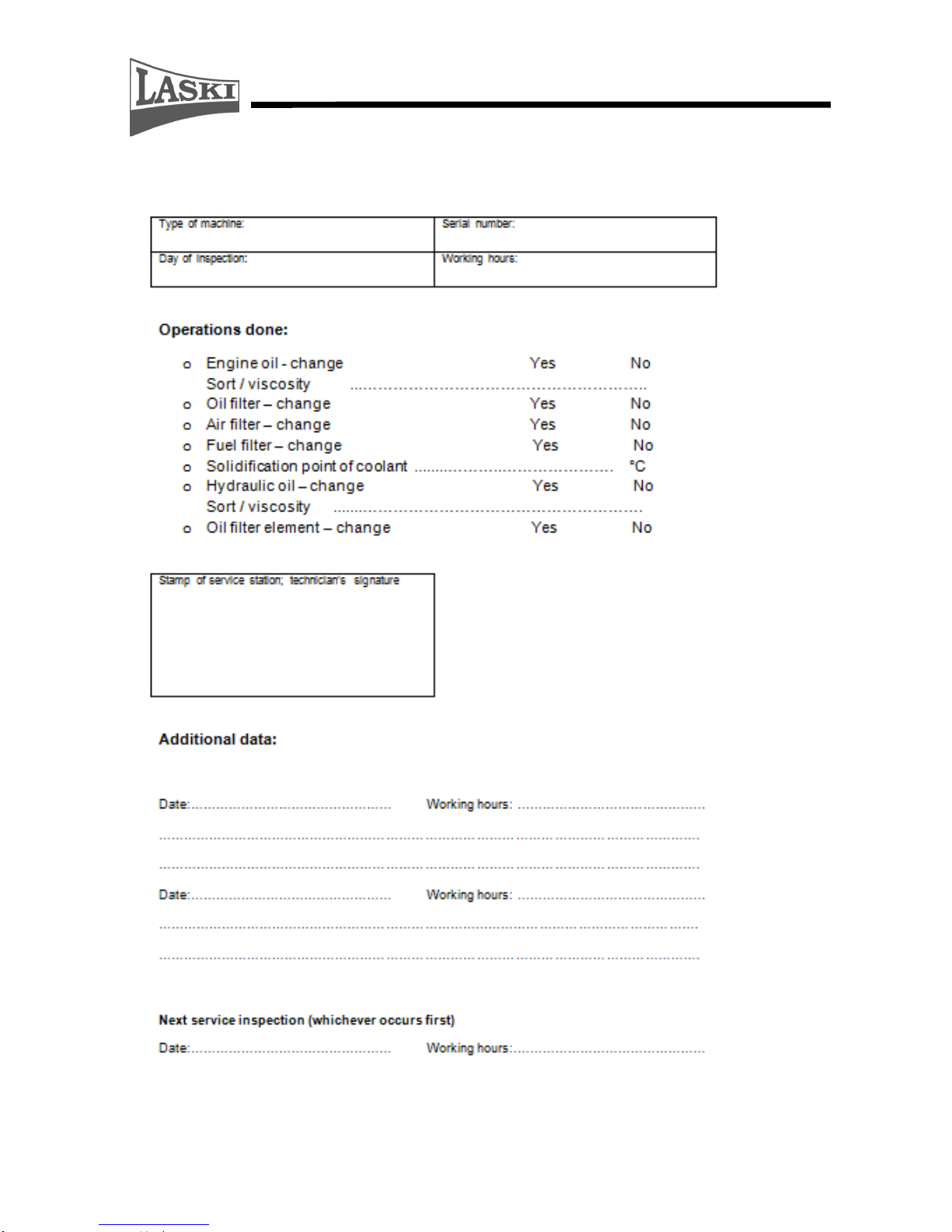
46
Service Report
Page 47

47
Service Report
Page 48
48
Service Report
 Loading...