


COD. 79101EN.00
11/2013
BIOSELF
MULTIFUEL BOILER
USER AND INSTALLATION MANUAL

COD. 79101EN.00
11/2013
2
COD. 79101EN.00
11/2013
3
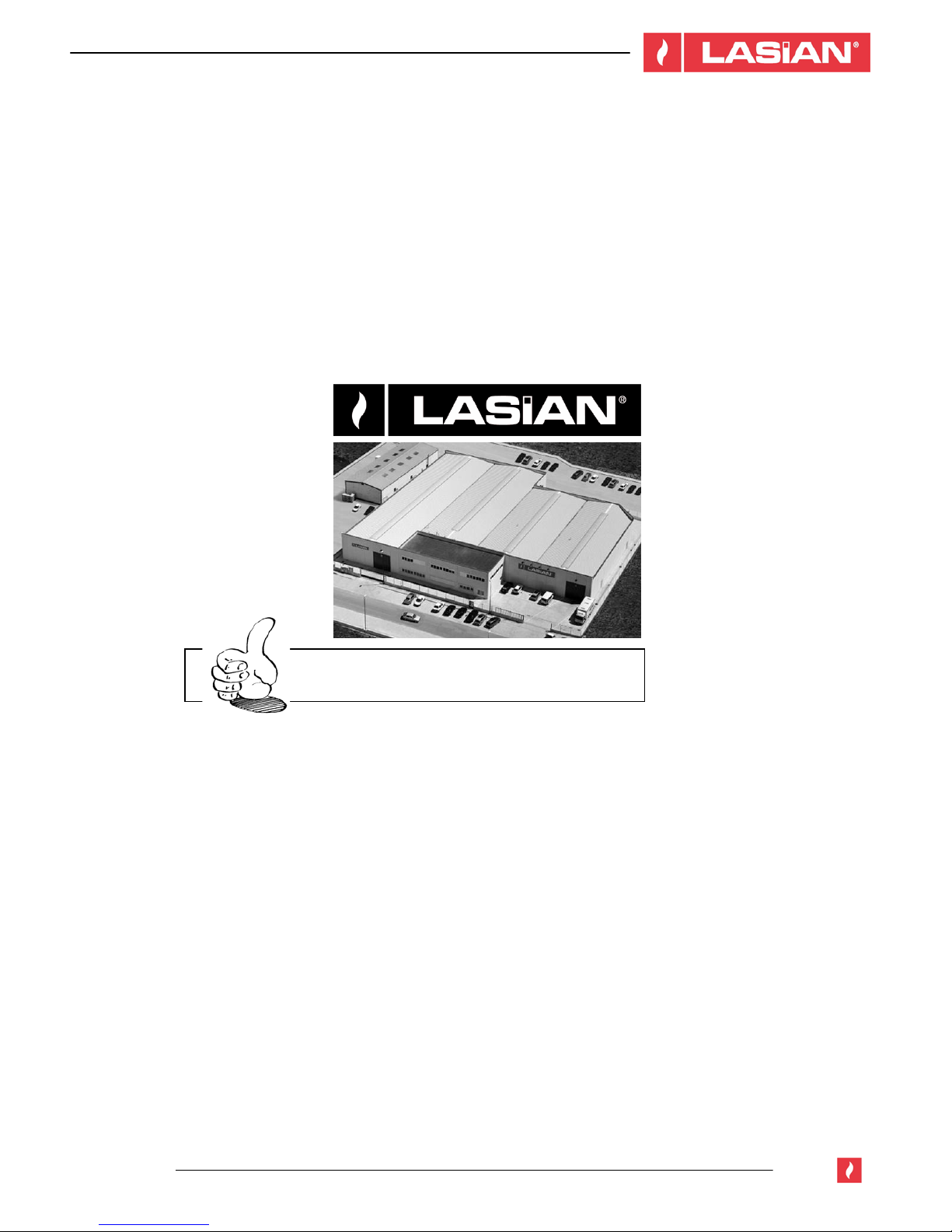
LASIAN Tecnología del Calor, S.L.
g
ives thanks for trust in us
¡THANKS FOR PURCHASING THIS PRODUCT!

COD. 79101EN.00
11/2013
4

COD. 79101EN.00
11/2013
5
DECLARATION OF CONFORMITY
In compliance with the requirements of the COUNCIL OF THE EUROPEAN UNION
The Company LASIAN Tecnología del Calor, S.L.
with C.I.F. B50141894, and registered address at:
Políg. Ind. Las Norias, parcela nº 7 - 50450 MUEL (Zaragoza) - SPAIN
Manufacturer of boilers for production of heating and A.C.S,
brand: LASIAN
In its different models:
BIOSELF 18 kW
BIOSELF 24 kW
WE HEREBY DECLARE, under our sole responsibility, that the above mentioned products are
manufactured in accordance with the following directives and standards:
98/37 CE
2006/95 CE
89/336/ CEE
Real Decreto 1027/2007
UNE - EN 303-5
Muel, 20th March 2013
The characteristics and manufacture date on each unit are indicated in the technical documentation that accompanies each
boiler.
COD. 79101EN.00
11/2013
6
Users of this boiler must read and understand this entire manual. The manual and all the documentation provided
must be kept during all the life-cycle of the boiler in an easily accessible place.
Care of the manual and how to consult it
Take care of this manual and keep it in an easily accessible place.
Should the manual be misplaced or ruined, request a copy from your installer or directly from the manufacturer
giving the identification details of the product.
“Bold text” requires particular attention.
Text in “italics” is used to draw your attention to other paragraphs in this manual or any additional explanation.
SYMBOLS USED IN THE MANUAL
SYMBOL MEANING: EXPLANATION, ADVICE, NOTES
ATTENTION!
Carefully read and understand the relative message. Failure to comply with
what is written can cause serious damage to the boiler and put the user’s
safety at risk.
OPERATING SEQUENCES
Sequence of buttons to be pressed to access the menus or make adjustments.
INFORMATION
Important information for a good performance of the boiler. Failure to comply
with these provisions will compromise the use and performance of the boiler.

COD. 79101EN.00
11/2013
7
INDEX
1. IMPORTANT INSTRUCTIONS ................................................................................................................................9
2. TECHNICAL DATA.................................................................................................................................................10
3. FUEL.......................................................................................................................................................................12
4. INSTALLATION ......................................................................................................................................................13
4.1 GENERAL NOTES...........................................................................................................................................13
4.2 UNPACKING ....................................................................................................................................................13
4.3 DOMESTIC FIRE PREVENTION.....................................................................................................................13
4.4 MINIMUM SAFETY DISTANCE.......................................................................................................................14
4.5 FLOOR PROTECTION ....................................................................................................................................15
4.6 DUCT OR CHIMNEY .......................................................................................................................................16
4.7 FLUE DUCT OUTLET ......................................................................................................................................17
4.7.1 GENERAL NOTES ...................................................................................................................................17
4.7.2 PIPES AND MAXIMUM USABLE LENGTHS ...........................................................................................17
4.7.3 HOLE IN FLUE DUCT PIPE .....................................................................................................................18
4.7.4 USE OF A TRADITIONAL TYPE CHIMNEY ............................................................................................18
4.8. USE OF EXTERNAL CHIMNEY .....................................................................................................................19
4.9 EXTERNAL CHIMNEY.....................................................................................................................................19
4.10 FRESH AIR INTAKE ......................................................................................................................................21
4.11 MINIMUM DISTANCES FRESH AIR INTAKE ...............................................................................................21
5. CONNECTIONS .....................................................................................................................................................22
5.1 ELECTRICAL CONNECTION..........................................................................................................................22
5.2 HYDRAULIC CONNECTION ...........................................................................................................................22
6. USE ........................................................................................................................................................................23
6.1 WARNINGS......................................................................................................................................................23
6.2 CONTROL BEFORE IGNITION.......................................................................................................................23
6.3 LOADING THE PELLETS ................................................................................................................................24
6.4 IGNITION OF THE BOILER.............................................................................................................................24
6.5 CLEANING .......................................................................................................................................................24
6.6 LOAD................................................................................................................................................................24
6.7 PAUSE .............................................................................................................................................................24
6.8 WAITING FOR THE FLAME ............................................................................................................................24
6.9 FLAME STABILIZATION..................................................................................................................................24
6.10 IN OPERATION..............................................................................................................................................24
6.11 SHUTDOWN ..................................................................................................................................................25
6.12 NOT WORKING .............................................................................................................................................25
6.13 STANDBY ......................................................................................................................................................25
6.14 PROTECTION CONTROL OF THE BOILER OFF OR IN STANDBY............................................................25
6.15 WATER PUMP CONTROL.............................................................................................................................25
7. CONTROL PANEL INSTRUCTIONS .....................................................................................................................26
7.1 START-UP SCREEN .......................................................................................................................................26

COD. 79101EN.00
11/2013
8
7.2 PROGRAMS MENU.........................................................................................................................................27
7.3 BOILER TEMPERATURE PROGRAMMING...................................................................................................27
7.4 DATE AND TIME ADJUSTMENT ....................................................................................................................27
7.5 PROGRAMMED START-UP AND SHUTDOWN.............................................................................................28
7.6 FUEL ................................................................................................................................................................32
7.7 PRESSURE H
2
O..............................................................................................................................................32
7.8 ALARM DESCRIPTIONS.................................................................................................................................33
7.9 SAFETY TEMPERATURE LIMITER AND ROOM THERMOSTAT.................................................................34
8. WARNINGS AND MAINTENANCE ........................................................................................................................35
8.1 DOOR OPENING .............................................................................................................................................35
8.2 DISPOSAL OF ASHES ....................................................................................................................................35
8.3 BRAZIER CLEANING ......................................................................................................................................35
8.4 ASH PAN CLEANING ......................................................................................................................................35
8.5 COMBUSTION CHAMBER CLEANING ..........................................................................................................36
8.6 HEAT EXCHANGER CLEANING ....................................................................................................................36
8.7 SMOKE CHAMBER CLEANING......................................................................................................................37
8.8 UNLOAD INSTALLATION CLEANING ............................................................................................................37
8.9 PEEPHOLE GLASS BREAKAGE ....................................................................................................................37
8.10 ORDINARY AND EXTRAORDINARY MAINTENANCE ................................................................................37
* WARRANTY CONDITIONS

COD. 79101EN.00
11/2013
9
1. IMPORTANT INSTRUCTIONS
This instruction manual has been prepared by the manufacturer and it is an essential part of the product. Should
the boiler be sold or transferred, it should always be accompanied by the manual as it contains information that is
necessary for the buyer and all persons involved in the installation, maintenance and use of the product.
Carefully read and understand the instructions and technical information contained in this manual before
proceeding with the installation, use and maintenance of the product. Familiarization of the instructions in this
manual ensures the safety of people and a longer life performance of the product.
The manufacturer disclaims any liability for damage caused by failure to read the rules and instructions for
installation, use and maintenance listed in the book of instructions, unauthorized product modification or use of
non-original spares.
Installation and use of the product should be in accordance with the manufacturer's instructions, obeying European,
national and local regulations.
Installation, electrical connection, maintenance and repairs must be performed only by a qualified, authorized
person and with a proper knowledge of the product.
The product should not be installed near wooden walls or combustible material. For a proper installation it is
necessary to consult the chapter "Safety distance". Check the flatness of the floor where the product will be
installed. Use of appropriate gloves is advised when handling coated parts to avoid leaving traces that are difficult
to remove in the first cleaning. The assembly of the boiler should be carried by at least two people.
Connect the boiler to the mains only after connecting the chimney. The power cable must be accessible after the
installation of the boiler. To start the boiler refer to chapter "FUEL". Never use liquid fuels to start the boiler.
Provide sufficient ventilation during the installation. In case of malfunction, the fuel supply will be interrupted.
Restart the product only after having the cause of the problem solved. Stop using the product in case of failure or
malfunction. Do not lift the grating which lies inside the fuel hopper. Any accumulation of unburned fuel in the
burner resulting from misfire must be removed before ignition.
While the boiler is working, it is recommended not to touch the hottest parts like handle, door and chimney. Pay
attention to keep anyone not involved in the installation away from the boiler. Inform persons in the vicinity of the
boiler of the necessary precautions while the product and possible products are working. In case of problems or
misunderstandings of the instructions, contact the installer. Do not place non heat-resistant objects on the boiler or
within the prescribed minimum safety radius of the boiler.
Do not open the door during operation, or start the boiler if the peephole glass is broken.
For terms, limits and exclusions refer to the warranty certificate supplied with the product. The manufacturer may
make changes deemed appropriate to the boiler documentation without notice, to pursue a policy of constant
development and constant renewal of the product.
This document is property of the manufacturer and can not be transferred in whole or in part to any third party
without the written consent of the company. All rights
reserved.
DIRECTIVES AND STANDARDS
All our products are manufactured according to the following directives:
89/366 CEE
2004/108 CE
2006/95 CE
89/106 CEE
All our products are manufactured according to the following standards:
EN 60335-1; EN 60335-2-102;
EN 61000-3-2; EN 61000-3-3;
EN 50366; EN 55014-1; 55014-2
EN 303-5

COD. 79101EN.00
11/2013
10
2. TECHNICAL DATA
The technical label indicates data and performance of the appliance.
The handling, removal or lack of technical label hinders any installation and maintenance, since it is not possible
to identify the product. In case of damage, request a duplicate of it to the service center. Given the importance of
the label, we recommend installing the boiler respecting the distances so that it is always visible.
MODEL
BIOSELF 18 kW BIOSELF 24 kW
Nominal thermal output
min./max.
kW
6,2 - 18
8,5 - 24
Nominal thermal output to
water
kW
16
20
Efficiency %
>92 >89
Consumption hourly
min./max.
kg/h
1,3 – 3,7
1,9 - 5,1
Tank capacity
kg
95 95
Electric absorment in work
W
50 - 150
50 - 150
Flue duct Ø
80 mm 80 mm
Weight
kg
177 182
Dimensions
LxBxH 550x700x1450 550x700x1450
COD. 79101EN.00
11/2013
11
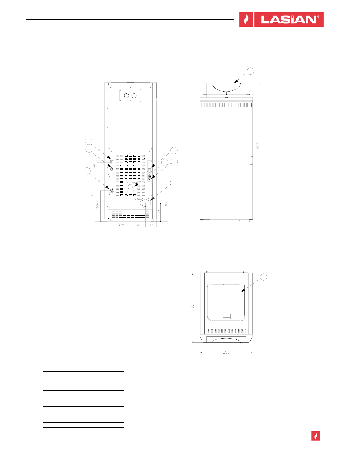
DIMENSIONS AND COMPONENTS MODELS BIOSELF 18 / 24 kW
BIOSELF 18 / 24 kW
2
1
7
6
4
5
3
9
8
COMPONENTS
1 Control panel
2 Ø 80 Flue duct
3 Safety valve
4 ¾ male discharge
5 ¾ male return
6 Air intake
7 Electrical outlet
8 Hopper lid
9 Room thermostat connection
COD. 79101EN.00
11/2013
12
3. FUEL
The multi-fuel boiler is designed to burn fuels derived from solid biomass:
Wood pellet: is a fuel made from compacted sawdust extracted from the remains of the production and processing
of dried natural wood; the compactness of the product is guaranteed over time by a natural substance contained in
the wood: the lignin. The typical form resembling small cylinders is achieved by wire drawing.
On the market there are various types of pellet with quality and features that change depending on the kind of
production and type of wood materials used.
Solid biomass: biomass is a type of fuel recovered and produced directly or indirectly from the disposal of
industrial processing, from substances such as olive, almond, hazelnut, rape or pruning cuts, or from the disposal
during wood processing or the remains. These fuels are materials such as shredded vegetables including olive pits,
almonds or hazelnut shells; other types are the pellet boiler and pellet olive of a diameter of 6 or 8 mm. etc. This
LASIAN boiler has an ash cleaning system that allows these fuels to be used in the devices, choosing the specific
program that is already recorded for the fuel we use:
FUEL PROGRAMS:
Combustible 1 DIN PLUS
Combustible 2 PELLET QUALITY MEDIUM
Combustible 3 PELLET QUALITY LOW
Combustible 4 OLIVE PITS
Combustible 5 SHREDDED ALMOND SHELL
The importation of these programs can be found in chapter 8 Operation of the control panel, in the
paragraph 8.6.
ATTENTION!
The boiler is provided with two burners, one for the pellets and shredded almond shell
combustion (which is factory assembled) and another specific burner for olive pits combustion.
When you select the program “Combustible 4” for burning olive pits, the pellet burner must be
replaced by the olive pits burner, which has smaller holes.
The following types of fuel are excluded for its use; splinters - wood chunks - branches in
general.
Because the characteristics and fuel quality influence significantly in the autonomy, performance and
proper operation of the boiler, it is advised to:
AVOID the use of fuel containing powder of mixed sawdust, resins or chemical, additional or binder substances.
AVOID the use of wet fuel.
The choice of unsuitable fuel causes:
- brazier and smoke exhaust dust jam,
- increase in fuel consumption,
- decrease in performance,
- does not guarantee the normal operation of the boiler,
- glass dirt,
- production of unburned granules.
The presence of moisture in the fuel increases the volume of the capsules and breaks them causing:
- malfunctions of the load system,
- bad combustion.
Fuel must be stored in a dry place and special attention must be paid to the handling of the sacks in order to avoid
grinding them and form sawdust.
In order to use a fuel with size and calorific characteristics calorific different to the ones specified, it could be
necessary to modify the operating parameters of the boiler. Should that be your case, contact an authorized service
center.
COD. 79101EN.00
11/2013
13
The use of fuel not according to the manufacturer's instructions can damage the boiler and
compromise its performance, resulting in the invalidation of the warranty and in the end of the
liability of the manufacturer on the product.
4. INSTALLATION
4.1 GENERAL NOTES
Do not install the boiler in bedrooms, locations with bath or shower and in places where there is another heating
unit devoid of an adequate airflow (chimney, stove, etc.), outside exposed to the atmospheric agents or in wet
areas.
The installation of the boiler must be in a location that allows a safe and easy use and a simple maintenance. This
place must also be equipped with an electrical outlet with a regulatory earth connection.
The external air intake must meet the requirements of paragraphs 4.10 and 4.11.
ATTENTION!
Ensure that the plug for the electrical connection is accessible after the boiler
installation.
4.2 UNPACKING
Unpack the product carefully so it does not get damaged or scratched. Remove from the tank of the boiler, the
accessory and home box possible pieces of polystyrene or cardboard used to block the removable parts, etc.
Also keep out of reach of children parts of the packaging (plastic bags, polystyrene, etc.) that could be potentially
dangerous and dispose according to the existing laws.
4.3 DOMESTIC FIRE PREVENTION
- The installation and use of the boiler must comply with the manufacturer's instructions and local siting
regulations.
- Always consult the instructions given in this manual for a correct use of the boiler and the electronic devices
connected to it.
- When a chimney crosses a wall or ceiling it is necessary to perform particular operations (protection, thermal
insulation, distance of heat sensitive materials, etc.)
- The chimney connection pipe should never cross a combustible surface.
- Do not connect this boiler to another smoke duct already used by another device.
- It is recommended to keep out of the heat source area and at least at one meter all flammable or combustible
items such as wooden beams, furniture, curtains, flammable liquids, etc...
- In the event that there are flammable or heat sensitive coatings in the surrounding space, a protective layer of
insulating and not combustible material must be placed. If the floor is made of combustible material, fireproof
material protections projected 15 cm laterally and 30 cm from the front must be placed.
- For further information refer to local regulations.
- If the flue should catch fire, be equiped with a suitable systems for suffocating the flames or request help from
the fire service.
COD. 79101EN.00
11/2013
14
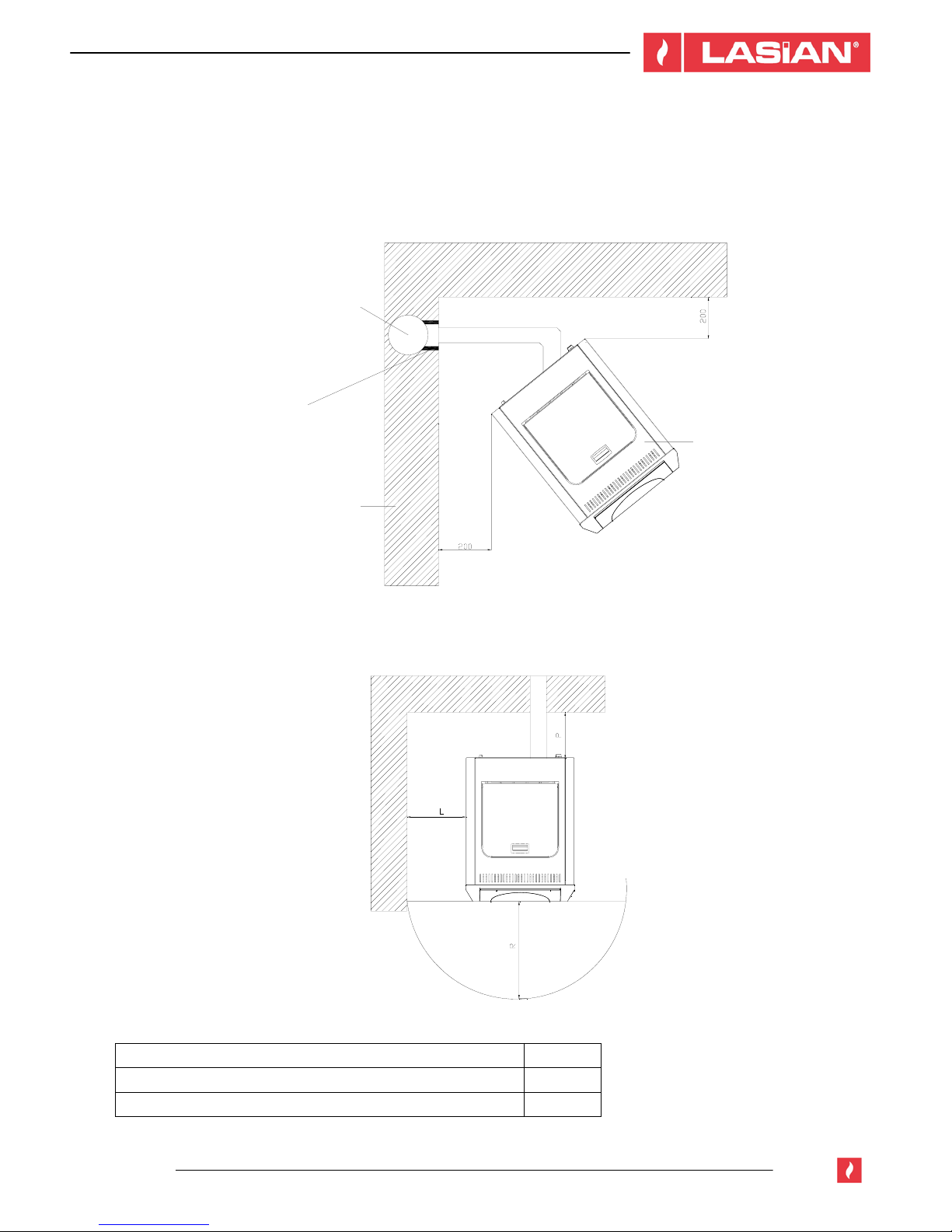
4.4 MINIMUM SAFETY DISTANCE
The following figures show the minimum safety distance that must always be guaranteed.
INSTALLATION IN ANGLE (mm)
INSTALLATION TO WALL (mm)
Safety distance of the flammable material mm
minimum distance air from flammable posterior wall P = 400
minimum distance air from flammable side wall L = 400
front distance of flammable material R = 1000
Chimmey
Passing pipe
insulation
Walls
Boiler

COD. 79101EN.00
11/2013
15
DISTANCE FROM FALSE CEILINGS OR
FLAMMABLE CEILINGS (mm)
DISTANCE FROM THE FLUE DUCT OF
FLAMMABLE WALLS INSTALLATION (mm)
4.5 FLOOR PROTECTION
In case of heat sensitive or flammable floors is necessary to use a floor protection, eg: Steel sheet, marble or tiles.
Whatever type of protection is chosen, it must protrude at least 300 mm from the front, and at least 150 mm from
the sides of the boiler, support the weight of the boiler and have a thickness of at least 2 mm fig. 6 and 7.
Fig. 6
Fig. 7
2 mm protection
Floor
Boiler
Protection

COD. 79101EN.00
11/2013
16
4.6 DUCT OR CHIMNEY
Each appliance must have a vertical duct or chimney to expel outside the fumes produced by combustion.
Flue duct must meet the following requirements:
Do not connect to any other fireplace, boiler, boiler or any kind of extractor (fig. 1)
It must be adequately separated from combustible or flammable materials by a cavity wall or an insulating material.
The inner section should be uniform, preferably circular: square or rectangular sections must have rounded edges
with a radius of at least 20 mm; regular bends without discontinuities, deviations from the axis no greater than 45°
(Fig. 2).
Each appliance must have its flue duct with a section equal to or greater than the diameter of the flue outlet duct of
the boiler and a height of not less than that declared (See table in paragraph 4.7.2).
Two boilers, fireplace and a boiler, an oven and a wood boiler, etc. should never be used in the same environment
since the draw of one may damage the other. Collective type ventilation ducts cannot be used either as they could
cause a vacuum in the environment of installation, even if installed in adjoining or communicating rooms.
It is forbidden to perform fixed or mobile openings in the chimney to connect a different appliance.
It is advisable that the flue is equipped with a solid material collection chamber and possible condensations
beneath the mouth of the duct to be easily opened and inspected from the door hermetically.

COD. 79101EN.00
11/2013
17
4.7 FLUE DUCT OUTLET
4.7.1 GENERAL NOTES
ATTENTION!
The use of various fuels distinguishes this boiler from the others. The draw of the smoke is
forced thanks to an extractor that keeps the combustion chamber in depression and all the
discharge pipes under a slight pressure. It is required to verify that this extractor is installed
correctly and completely tight and firm, both for performance and safety.
The exhaust duct must be built by specialized staff or companies, as indicated in this manual. Always carry out the
unloading installation so that periodic cleaning is assured without having to dismantle any part.
Pipes should ALWAYS be sealed with silicone, not cement-based, which retains their strength and elasticity at high
temperatures, 250 ° C, and should be fixed with a Ø3, 9mm. self-tapping screw.
- Do not install dampers or valves that could block the passage of flue gas.
- Do not connect to a flueway where other appliances (boilers, extractor hoods, etc.) discharge fumes or vapours.
4.7.2 PIPES AND MAXIMUM USABLE LENGTHS
Pipes of painted aluminium-clad steel (minimum thickness of 1.5 mm), stainless steel (Aisi 316) or enameled steel
(minimum thickness of 0.5 mm) with a nominal diameter of 80 mm can be used; for pipes which run inside the flue
the maximum diameter is 150 mm.
Hoses are admitted if they meet the specifications set by law (stainless steel with a smooth inner wall) and malefemale connectors must have a minimum length of 50 mm.
The diameter of the pipes depends on the type of installation; the boiler was designed to take Ø80 mm pipes, as
shown in the specifications of the model chosen, and in some cases and models it is necessary to use Ø100 mm
double-walled pipes.
TYPE OF INSTALLATION WITH Ø 80 mm PIPE
WITH DOUBLE-WALLED
Ø 100 mm PIPE
Minimum length 1.5 m 2m
Maximum length (with three 90° bends) 4.5 m 8m
For installations more than 1200m above the sea - required
Maximum number of bends 3 4
Length of horizontal sections with minimum
5% gradient
2m 2m
NOTE: Losses in pressure associated with a 90 ° bend can be compared to those incurred by one meter of pipe;
an inspectable union-tee can be considered equivalent to a 90 ° bend.
Tee
Ø80>Ø100 connection
Sealing plug
Direction of cleaning
Direction of cleaning
Direction of
cleaning
Tee
Tee
Tee
Max. 2m (min 5%)

COD. 79101EN.00
11/2013
18
4.7.3 HOLE IN FLUE DUCT PIPE
Once the boiler location is established, it is necessary to make the hole for the flue duct pipe. This varies
depending on the type of installation, diameter of the unloading pipe and type of wall or ceiling that it is going to
pass through.
The insulating barrier must be mineral-based (rock wool, ceramic fiber) with a nominal density greater than 80
kg/m
3
.
Diameter flue duct pipe [mm]
Ø80
Up to 24 kW
Ø 100
From 28 kW
Insulation
thickness [mm]
Diameter holes to be done [mm]
Wall in flammable wood or with
flammable parts
100 280 300
Wall or ceiling in cement 50 180 200
Wall or ceiling in brick 30 140 160
4.7.4 USE OF A TRADITIONAL TYPE CHIMNEY
If you wish to use an existing chimney it is strongly recommended that you have it checked by a professional
chimneysweep to ensure that it is completely airtight. The reason for this is that the smoke, because it is slightly
pressurized, can infiltrate any cracks in the flue and escape into living spaces.
If upon inspection you find that the chimney is not completely sound, it is recommended that you insert piping made
of new material.
If the existing chimney is wide enough, we recommend a pipe with a maximum diameter of 150 mm; it is also
recommended that you insulate the chimney flue. Fig. 1 and 2 represent the solutions to be adopted if you want to
use an existing chimney.
Fig. 1
Fig. 2

COD. 79101EN.00
11/2013
19
4.8. USE OF EXTERNAL CHIMNEY
An external flue can be used provided it complies with the following requirements:
• Use only insulated double-walled
stainless steel pipes fixed to the
building.
• There must be an inspection opening at
the base of the flue to permit periodic
checks and maintenance.
• The chimney must be fitted with a down-
draught cowl ensuring compliance with
the safety distance from the edge of the
building as outlined in paragraph 4.9.
• The drawing represents the solution
adopted to use an exteral chimney.
4.9 EXTERNAL CHIMNEY
The flue duct must be equipped, in its upper part, with an appliance called chimney, which facilitates the discharge
of combustion gases outdoors.
The external chimney must comply with the following requisites:
- To have an internal section equivalent to the flue pipe.
- To have a useful outlet section of not less than twice of the flue pipe section.
- The chimney which emerges from the ridge or that remains in contact with the outside (e.g. the case of an
open roof) must be covered with brick elements and perfectly insulated. They must be built in such a way to
prevent the penetration of rain, snow or foreign matter, and in the event of winds from all directions and angle,
discharge of the combustion products is assured (chimney stack with down-draught cowl).
- The external chimney must be installed to ensure the adequate dispersion and dilution of the combustion
products outside the reflux area. This area has different sizes and shapes depending on the angle of inclination
of the roof, and it is therefore necessary to adopt the minimum heights shown in Fig 1 and Fig 2.
- The chimney must be a windproof type and surpass the ridge height like in fig.1 and fig.2.
- Any building or other obstacles that exceed the chimney height cannot be near the chimney itself (Fig. 1).
- Never cover the chimney with nets.
Inspection
Fresh air intake with nonclosable grille

COD. 79101EN.00
11/2013
20
Fig. 1
Fig. 2
Pitch of the roof
[°]
Horizontal width of reflux
area from ridge axis A[m]
Minimum height of
outlet from roof
Hmin =Z+0.50m
Height of reflux area Z
[m]
15 1.85 1.00 0.50
30 1.50 1.30 0.80
45 1.30 2.00 1.50
60 1.20 2.60 2.10
Surpass

COD. 79101EN.00
11/2013
21
4.10 FRESH AIR INTAKE
- The boiler must have the necessary air to ensure a trouble-free and correct performance of the combustion, as
well as a good environment.
- Make sure the room where the boiler is installed has adequate ventilation, and if not, install an air supply duct
from the outside with a recommended minimum section of 100 cm².
- The fresh air intake must be communicated directly with the environment of the installation of the boiler, placed
so that it avoids to get obstructed, and it is protected with a permanent grid or another suitable guard provided
it does not reduce the minimum section.
- The air flow can also be obtained from an adjacent room to the place of the installation, provided this air flows
freely through permanent apertures that cannot be closed, and communicate with the outside.
- The adjacent room must not be used as a garage, store for combustible materials or for activities with a risk of
fire.
4.11 MINIMUM DISTANCES FRESH AIR INTAKE
The combustion air intake cannot be connected to any air distribution duct or to the air intake placed in the
wall.
These distances must be respected to prevent the combustion air being released from another source; for example
opening of a window can take the fresh air causing the lack of it to the boiler.
Air intake must be placed at least:
1.5 m Under
1.5 m Horizontally far from
0.3 m Above
Doors, windows, flue duct,
cameras, etc.
1.5 m Far from Flue duct

COD. 79101EN.00
11/2013
22
5. CONNECTIONS
5.1 ELECTRICAL CONNECTION
The system must be suitable for the electrical power of the boiler.
The boiler is supplied with a power cable that needs to be connected to
a 230V 50Hz outlet.
The connection of the outlet to the back of the boiler is shown in the
figure.
Ensure that the main switch of the boiler is at 0, and then connect the power cord first behind the boiler and then
into an electrical outlet on the wall. The main switch located on the back wall will be activated only when the boiler
is lit; otherwise, it is advisable to remove the cable from the boiler.
Maximum electrical absorption while ignition (6 min) 490 Wat
Electrical absorption (Wat) 120 Wat
Voltage and supply frequency 230 V / 50Hz
By law, the installation requires an earth connection and residual-current circuit breaker (RCCB). Make sure the
power cord, in its definitive position, does not make contact with hot parts.
5.2 HYDRAULIC CONNECTION
For the connection of the input water, output water, unloading and filling pipes, use long
flexible tubes of at least 70 cm to facilitate the movement of the boiler for maintenance.
INDICATIVE HYDRAULIC SCHEME
From the aqueduct to
water reintegration
Output water heating installalation
Input water heating installation
Closing flange
Non-returning valve
Pressure reducing valve

COD. 79101EN.00
11/2013
23
6. USE
6.1 WARNINGS
- Do not use the appliance as an incinerator or in any other way different to the purpose it has been designed
for.
- Do not use liquid fuel.
- The appliance, especially the external surfaces, reaches high temperatures during operation; maneuver
carefully to avoid burns.
- Do not make any unauthorized modification to the appliance.
- Use only original spare parts recommended by the manufacturer.
- Try to familiarize yourself with the commands given by the panel or by the remote control.
- Try to incidentally memorize the boiler messages displayed on the screen.
- To prevent the escape of fumes, the combustion chamber must be kept closed, except during cleaning
operations, which are conducted with the boiler off.
- Do not remove the protective grille inside the tank.
- Do not touch the boiler with wet hands, as this is an electrical appliance. Always remove the power cord before
intervening in the unit.
- Incorrect installation or poor maintenance (non-compliant to what it was stated in this manual) may cause
damage to people, animals... In this case, Lasian will be exempt of any civil or criminal liability.
- If during the ignition phase, this does not occur and you notice a lot of smoke in the combustion chamber, turn
off the boiler and replace the fuel as the humidity could be too high. Remove any rest of fuel in the crucible
caused by misfire before restarting the boiler.
During the first ignition, it is important to increase the boiler temperature gradually avoiding
using the maximum power or overheating it.
The boiler is subject to expansion and contraction during the ignition and cooling phases. The
phenomenon is quite normal since the structure is made of steel and therefore should not be
considered a defect.
6.2 CONTROL BEFORE IGNITION
Make sure you have followed all the safety conditions seen before. Having read and understood the operating
instructions:
- Remove from the boiler anything that can get burned (instructions, labels, stickers).
- Check that the brazier is standing properly on its base.
Ensure that all doors and air intake of the combustion chamber and ash pan are closed properly to avoid drops in
performance and possible leakage of fumes during operation.
After a long inactivity, the remains of pellets will need to be removed from the tanks as they may
have absorbed some moisture, changing its original features and not being suitable for
combustion.

COD. 79101EN.00
11/2013
24
6.3 LOADING THE PELLETS
The load of fuel is made through the upper side of the boiler. Pour the pellet in the tank.
Never remove the protection grille inside the tank. During the load, prevent the sack of pellet
from contacting hot surfaces. Fill the tank only with the fuel that meets the aforementioned
specifications.
6.4 IGNITION OF THE BOILER
Press the button ON/OF during more than 3 seconds, the boiler will pass to mode on, on the screen will appear
the word “FIRE”.
Subphases “ON”:
The start phase is composed by 5 phases which occur in the following order: “CLEANING”, “LOAD”,
“PAUSE”, “WAITING FLAME” and “FLAME STABILIZATION”. These phases are described below.
6.5 CLEANING
Burner cleaning phase. The burner motor is working for a defined time and the fume motor at a defined speed.
6.6 LOAD
Continuous load of fuel into the burner, preheating of the resistor. The burner motor turns off, while the fume motor
continues running at the defined speed.
6.7 PAUSE
Loading auger still, fume motor at the defined speed and resistor on.
6.8 WAITING FOR THE FLAME
Waiting phase when the ignition must take place; the auger motor starts working again for a defined time. The
transition to the next phase is permitted when the fumes temperature exceeds the threshold and during the next 90
seconds there is an increase of 3 ° C of such temperature. If such increase does not occur in the first 90 seconds,
other records are made, always in intervals of 90 seconds, until it reaches an increase of at least 3 ° C; all within a
time limit defined by a parameter. If the waiting for the flame phase does not come to fruition, the alarm of " FAILED
IGNITION" will be activated. During this phase, the fume motor rotates at a defined speed.
6.9 FLAME STABILIZATION
Stabilization phase after the presence of the flame with an intermediate load of fuel. The fume motor, at a defined
speed, and the auger, at a defined speed, are active while the resistors for the ignition of the flame are off.
6.10 IN OPERATION
Phase of regular operation of the burner with a variation of the power from 1 to the maximum programmed in
function of the temperature of the boiler. The modulation of the operating conditions is made according to the
parameters.
During this phase 3 types of control take place:
Temp. Control. Maximum fumes: if the maximum temperature of the fumes is exceeded, the auger starts working
in regimen 1.

COD. 79101EN.00
11/2013
25
Temp. Control. Maintenance: if the fumes temperature falls below the maintenance temperature for more than 3
minutes, the current regimen of operation is increased to the next regimen.
Extinct of flame control: if the fume temperature decreases below the extinction of the flame temperature, flame
extinction alarm is activated.
6.11 SHUTDOWN
Timed shutdown phase subdivided into two subphases regulated by two parameters:
1) fume motor at maximum regimen and the auger off;
2) fume motor at maximum regimen and start-up of the burner motor.
If after this subphase the fumes temperature is still higher than the shutdown temperature programmed by the
parameter, the fume motor continues running while the burner motor shuts off.
NOTE: if you press the button ON / OFF during 3 seconds, the boiler is forced to pass from the TURN OFF state to
the OFF state.
6.12 NOT WORKING
NOTE: If at this stage the fumes temperature is higher than the initial temperature, the fume motor is activated.
During the ignition phase (load, pause, wait and flame stabilization), it is not possible to switch
off the boiler: you need to wait.
Similarly, if it is in the shutdown phase, the ignition cannot be forced again.
6.13 STANDBY
The boiler pass from the “ON” state to the “STANDBY” state in the following cases:
1) When the water temperature of the boiler is higher than the SET POINT temperature + the value of the
“OVERTCIMP” parameter;
2) When the "ROOM THERMOSTAT" has reached the required temperature.
The boiler returns to the “ON” state when the ROOM THERMOSTAT contact closes (the ignition will start when the
water temperature is lower than the SET POINT temperature, which is of 5 ºC).
6.14 PROTECTION CONTROL OF THE BOILER OFF OR IN STANDBY
If under these operating conditions is detected a boiler temperature higher than the protection temperature, the
pump starts working.
6.15 WATER PUMP CONTROL
If the water temperature of the boiler is lower than the “TEMP. ACC. POMPA” parameter, the pump does not run.
If the water temperature of the boiler is higher than the “TEMP. ACC. POMPA” parameter, the pump starts working
according to the conditions below:
1) If the boiler is off, the pump is inactive.
2) If the boiler is on, the pump is working.
3) If boiler is on “STAND BY”:
a) The pump starts to work if there is a water demand of the “ROOM THERMOSTAT”;
b) The pump will not work if there is not a water demand.

COD. 79101EN.00
11/2013
26
7. CONTROL PANEL INSTRUCTIONS
7.1 START-UP SCREEN
When the boiler is on, after a few seconds from the ignition, the display shows the following information on the
screen:
* During the operation phase, the screen shows the power of the boiler from 1 to 6. Using ▲ and ▼ the
power of the boiler can be increased or decreased manually.
Current date
current time
Mon
Operation regimen
from 1 to 6 when the
boiler is on *
Boiler state
Room temperature

COD. 79101EN.00
11/2013
27
Temp. boiler
Hours
Ignition
Pressure H2O
Combustible
7.2 PROGRAMS MENU
From the main screen you can access to the menu programs by pressing the SET button; using ▲ and ▼
the following screens will be displayed sequentially, from where you can leave at any time by pressing the
button
.
Once the parameter has been chosen, you can display/modify pressing the SET key to go to the submenu
or exit by pressing they key ON/OFF.
7.3 BOILER TEMPERATURE PROGRAMMING
After pressing Set to access the menu, press SET again to enter the submenu Temp. boiler.
It allows you to select the maximun temperature for the water boiler: Use
▲ and ▼ to set the temperature.
The range goes from 10 °C to 80 °C. Press SET to confirm and save or
the
to exit without saving the modification.
7.4 DATE AND TIME ADJUSTMENT
After pressing Set to access the menu, press SET again to enter the submenu Hours.
It allows you to change the day of the week: use the keys ▲ and
▼ to modify the day; press SET to confirm and access the
screen hours, or with the key
to pass to the screen hours
without modifying the day of the week.
Day of
week Tue
E
SC
SET <- ->
E
SC
SET <- ->
E
SC
SET <- ->
E
SC
SET <- ->
E
SC
SET <- ->
boiler 22.5oC
Temperature H
2
O
A
ccording to the screen, the function
of the keys change.
ESC SET
<- ->
Temp. boiler

COD. 79101EN.00
11/2013
28
It allows you to reschedule the current time. With the keys ▼
and ▲ you can modify the time; press SET to confirm or the key
to exit without saving the modifications.
7.5 PROGRAMMED START-UP AND SHUTDOWN
After pressing Set to access the menu, press SET again to enter the submenu Ignition.
This function allows you to switch on/off the boiler with
scheduled times: thanks to the internal clock and buffer battery
(CR2032 3V), which keep date and time in memory even without
power. There are up to 16 programs available, and each of them
allows you to define the start-up and shutdown time, and the
day/days of the week affected by each programming.
To activate the time: use they keys ▲ and ▼, to activate and
deactivate the time, when it is active, the green led is on. Pressing
SET the command is confirmed, and with the key
you exit
without saving any modification. If you activate the timer, you
access automatically to the first screen of programs.
This screen on the left will appear if we activate the timer, from
which we can see and modify the programs:
- TimerXX: number of program
- mtwtfss: days of the week from Monday to Sunday
- on00:00: time of activation
- off00:00: time of shutdown
Below you can see an example of a weekly schedule:
Example:
From Monday to Friday, the boiler starts at 10 am until 2 pm, and then from 5 pm to 11 pm. On Saturday and
Sunday from 8 am to 8 pm.
Go to the screen "IGNITION" and after selecting the keys ▲ and ▼ "SI", press the key SET, to gain access to the
programs screen.
The text “Timer01” flashes to show which program is selected.
To change the program it is necessary to press SET and then
change the value with the keys ▲ and ▼. In this case we leave
“Timer01“.
To go to the next parameter, press the key ▲ and this time the list with the days of the week flashes.
Pressing the key SET, the list "mtwtfss" will stop flashing and only
the first day of the week will be flashing. Now we need to decide
whether we include it in the schedule (Timer 01) or not. To switch
the active day, press ▲ and the flashing moves to the following
day. Every time you press ▼, the active day changes from lower
case to capital letter (and vice versa). The remaining days in capital
letter will be included in the schedule “on/off” of this program.
Hours
11:08
Ignition
Trigger
Timer YES
Timer01 mtwtfss
on00:00 off00:00
Timer 01 mtwtfss
on00:00 off00:00
Timer 01 mtwtfss
on00:00 off00:00

COD. 79101EN.00
11/2013
29
As you can see, only the days from Monday to Friday are
capitalized. Once the days are selected, press SET
to confirm: now the text “MTWTFss” will start flashing again.
To go to the next parameter, press the key ▲. The text “on00:00”
will now flash.
Now we can choose the desired start-up time for program 1
“Timer 01”, pressing SET and the text “on00:00” will stop
flashing.
With ▲ and ▼ we can select 10:00 and press SET to confirm. The
text "on10:00" will flash again. To move to the next parameter,
press ▲, and this time the text "off00: 00" flashes.
Now we can choose the desired shutdown time for program 1
“Timer01”, pressing SET and the text “off00:00” will stop
flashing.
With the keys ▲ and ▼ you can select the time 14:00 and press
SET to confirm it. From now on the text “off 14:00” will start
flashing again.
Now we are going to set the afternoon program from Monday to
Friday. We will follow the same procedure used to set the morning
programming but using “Timer 02”.
To start, we need to press ▲ so that the text “Timer 01” flashes.
When “Timer01” is flashing, it indicates that the programming is in
selection.
To be able to move to another programming, you need to press
SET.
Timer 01 MTWTFss
on00:00 off00:00
Timer 01 MTWTFss
on00:00 off00:00
Timer 01 MTWTFss
on10:00 off00:00
Timer01 MTWTFss
on10:00 off00:00
Timer01 MTWTFss
On10:00 off14:00
Timer01 MTWTFss
On10:00 off14:00

COD. 79101EN.00
11/2013
30
The text “Timer01” stops flashing: We change the value with the
keys ▲ and ▼ until the text “Timer02” appears. You will see that
when choosing a new program, all the days of the week appear
deactivated, and the connection/disconnection time (on/off) are all in
00:00.
To go to the next parameter press ▲ and the list of days of the week
will start flashing.
When pressing SET, the list “mtwtfss” will stop flashing and only
the first day of the week will flash. Now we need to decide whether
we include it in the schedule (Timer02) or not.
To change the active day, press ▲, and the flashing pass to the
following day. Every time you press ▼ the active day pass from
lower case to capital letter (and vice versa). The days in capital
letter will be included in the schedule “on/off” of this program.
As you can see, only the days from Monday to Friday are in capital
letter. Once the days are selected, press SET to confirm: now the
text “MTWTFss” will start flashing.
To pass to the next parameter press ▲. Now the text “on00:00” is
flashing.
Now we can choose the desired start-up time for program 2
“Timer02”, pressing SET and the text “on00:00” will stop flashing
.
With the keys ▲ and ▼ we set the time at 17:00 and press SET to
confirm it. From now, the text “on17:00” will start flashing again.
To pass to the next parameter, press ▲. Now the text
“off00:00” flashes.
Now we can choose the desired shutdown time for program 2
“Timer02”, pressing SET and the text “off00:00” will stop
flashing.
With the keys ▲ and ▼ we can set the time at 23:00 and
press SET to confirm it. From now on, the text “off 23:0 0” will
start flashing again.
We still have to program the schedule for the weekend. It is the
same procedure followed in the previous program but using “Timer
03”.
Timer02 mtwtfss
on00:00 off00:00
Timer02 mtwtfss
on00:00 off00:00
Timer02 MTWTFss
on00:00 off00:00
Timer02 MTWTFss
on00:00 off00:00
Timer02 MTWTFss
On17:00 off00:00
On17:00 off00:00
Timer02 MTWTFss
Timer02 MTWTFss
On17:00 off23:00

COD. 79101EN.00
11/2013
31
To start, we press the key ▲ so that the text “Timer02” starts
flashing.
When “Timer02” is flashing, it indicates that the program is in
selection.
To change to other programs, it is necessary to press SET.
The text “Timer02” stops flashing: We change the value with the
keys ▲ and ▼ until the text “Timer03” appears. We will see that
when choosing a new program, all the days of the week appear
disabled and the times of connection/disconnection (on/off) will all be
in 00:00. To go to the next parameter press ▲ and the list of the
days of the week will start flashing.
When pressing SET the list “mtwtfss” will stop flashing and only
the first day of the week will flash. Now we need to decide whether
we include it in the program (Timer03) or not.
To change the active day, press ▲, and the flashing pass to the
following day. Every time you press ▼ the active day changes from
lower case to capital letter (and vice versa). The days in capital
letter will be included in the schedule “on/off” of this program.
As you can see, only the days Saturday and Sunday are in capital
letter. Once the days are selected, press SET to confirm: now the
text “mtwtfSS” will start flashing again.
To pass to the next parameter press ▲. Now the text “on00:00”
is flashing.
Now we can choose the desired startup time for program 3
“Timer03”, pressing SET and the text “on00:00” will stop
flashing. With ▲ and ▼ we can set the time at 08:00 and press
SET to confirm it. From now the text “on08:00” will flash again.
To pass to the next parameter press ▲. Now the text “off00:00”
is flashing.
Now we can choose the desired startup time for program 3
“Timer03”, pressing SET
and the text off00:00” will stop flashing.
Timer02 MTWTFss
On17:00 off23:00
Timer03 mtwtfss
on00:00 off00:00
Timer03 mtwtfss
Timer03 mtwtfSS
on00:00 off00:00
Timer03 mtwtfSS
on00:00 off00:00
Timer03 mtwtfSS
on08:00 off00:00
Timer03 mtwtfSS
on08:00 off00:00
on00:00 off00:00

COD. 79101EN.00
11/2013
32
With the keys ▲ and ▼ we can set the time at 20:00 and
press SET to confirm it. From now the text “off 20:00” will
start flashing again.
The schedule is finished, with only three timings the startup and shutdown time for all the week has been set.
Having 16 timers available, allows covering different time slots for each day and different days of the week.
Once the schedule is ready, press the key
.
7.6 FUEL
After pressing Set to go to the menu, press SET again to go to the submenu.
It allows you to select up to 5 types of fuel. From the settings menu
press the key ▲ until this screen appears. Then, press the key
SET and, after we select the corresponding number of fuel with
the keys ▲ and ▼. With the key SET we confirm the selection,
and with the key
we exit without saving the modification.
FUEL PROGRAMS:
Combustible 1 DIN PLUS
Combustible 2 PELLET QUALITY MEDIUM
Combustible 3 PELLET QUALITY LOW
Combustible 4 OLIVE PITS
Combustible 5 SHREDDED ALMOND SHELL
If the boiler is going to burn olive pits, the burner pellet must be replaced by the olive pits burner, which
has smaller holes.
7.7 PRESSURE H
2
O
After pressing Set to go to the menu, press SET again to go to the submenu Pressure H2O.
From the main menu you can access to the menu Pressure H
2
O
using the keys ▲ and ▼. To enter press SET and you will see
the water pressure of the installation. Press the key
to exit.
Timer03 mtwtfSS
on08:00 off20:00
Combustible 1
Pressure H
2
O
bar 01,4
ESC SET <- ->

COD. 79101EN.00
11/2013
33
7.8 ALARM DESCRIPTIONS
ALARM DESCRIPTION SOLUTION
Lack of fuel in the tank Load fuel and try to switch on the boiler again
Presence of fuel remains in the
burner
Clean the burner and try to switch on the boiler again
Lack of fuel in the burner
Empty the tank with a long neck vacuum cleaner and
check if any object that could block the good performance
of the auger has fallen
FAILED IGNITION
If the problem persists call a T.A.S. in your area
Lack of fuel in the tank Load fuel and switch on the boiler again
Fuel not appropriated for the
program
Check the settings of the fuel
Empty the tank with a long neck vacuum cleaner and
check if any object that could block the good performance
of the auger has fallen
Lack of fuel in the burner
Reset the manual thermostat. See paragraph 7.9
TURN OFF FIRE
If the problem persists, call a T.A.S. in your area
Cleaning of the heat exchanger. See paragraph 8.6
Cleaning of the exhaust duct. See paragraph 8.8
MAINTENANCE
ORDINARY
Appears after 300 hours of
operation
To cancel the message, with the boiler off press the button
during a few seconds
MAINTENANCE
EXTRAORDINARY
Appears after 1000 hours of
operation
General cleaning of the appliance and the exhaust duct
installation, contact the T.A.S of the area
Check the flue duct
Check the chimney
Reset the manual thermostat. See paragraph 7.9
PRESSOSTATO
Pressure switch aperture
If the problem persists, call a T.A.S. in your area
When the boiler has been turned off, switch off and then on
again the switch ON / OF
SYSTEM ERROR
Program error
If the problem persists, call a T.A.S. in your area
GAS PROBE
Fumes probe not connected
Contact a T.A.S. in your area
Check the flue duct
Check the chimney
Reset the manual thermostat. See paragraph 7.9
AUGER MOTOR 1
Loading auger stopped
Contact a T.A.S. in your area
MOTOR FLUE GAS
The fume motor spins too fast or
too slow
Contact a T.A.S. in your area
Reset the manual thermostat. See paragraph 7.9
TERMICO COCLEA
Boiler protection opening
Contact a T.A.S. in your area
SONDA CALDAIA
Boiler probe not connected or
damaged
Contact a T.A.S. in your area

COD. 79101EN.00
11/2013
34
Check the water pressure. See paragraph 7.7
LOW PRESSURE H2O
Water pressure sensor opening
If the problem persists, call a T.A.S. in your area
Check the water pressure. See paragraph 7.7
HIGH PRESSURE H2O
Water pressure sensor opening
If the problem persists, call a T.A.S. in your area
Reset the manual thermostat. See paragraph 7.9
TERMICO H2O
Water temperature too high, the
flame turns off
If the problem persists, call a T.A.S. in your area
CONT. OPERATION
Loading auger is working, but it
has to be sttoped
Contact a T.A.S. in your area
- Any alarm switches the boiler off.
- To cancel any of the alarms, press the key
during 3 seconds, wait another 3 seconds and press again the
key
during 3 seconds (except the mantenimiento extraordinario alarm, see paragrah 9.6).
7.9 SAFETY TEMPERATURE LIMITER AND ROOM THERMOSTAT
As you can see in Fig. 1, the safety temperature limiter is situated on the back of the boiler. To carry out the manual
reset of this one, unscrew the cap and press the red button. Return to screw the cap, and then, press the key
during 3 seconds, wait another 3 seconds and press again the key during 3 seconds.
Fig. 1
Just above the safety temperature limiter is situated the room thermostat connection (see Fig. 2). To connect,
remove the connector pressing both switches (black and red), press them again when the connector has been
removed, and connect the room thermostat electrical wiring to the two terminals.
Fig. 2

COD. 79101EN.00
11/2013
35
8. WARNINGS AND MAINTENANCE
All maintenance operations (cleaning, possible replacements, etc.) must be made with the fire off and when the
boiler is cold.
Before carrying out any cleaning or maintenance, preventively ensure that the boiler is unplugged from the mains
intervening in the general switch placed behind the boiler or disconnecting the power cable that feeds it.
A LACK OF CLEANING CAN JEOPARDIZE SAFETY
8.1 DOOR OPENING
Door must be closed while running. Door must only be opened when the boiler is off and cold to carry out the
maintenance and normal cleaning.
8.2 DISPOSAL OF ASHES
The ash pan must be emptied regularly to avoid the combustion waste getting to the brazier stand. Ashes must be
placed in a metal container with a tight-fitting lid. Until the ashes are completely extinguished, the closed container
must be placed over a non-flammable base or land and far away from flammable materials.
8.3 BRAZIER CLEANING
Never open the door of the boiler until the display shows the
message “OFF”
This boiler has an ash cleaning system but, due to the fuel quality,
some incrustations can be formed and they will hinder the good
performance of the boiler, so they must be removed.
With an ash vacuum, vacuum the ash accumulated inside the
chamber, remove the brazier and control that the holes in it are clear.
Release the holes of incrustations using a sharp-pointed tool.
The frequency of this operation is determined by the frequency of use
and the choice of fuel. It is also important to control the brazier stand
vacuuming the existing ashes.
For this type of cleaning it is necessary to have a machine to vacuum the ashes
Before switching on the boiler, check that the brazier is put back towards the pipe of the
ignition resistor.
8.4 ASH PAN CLEANING
Once a week, empty the ash tray placed at the button of the boiler.
You will find the ash pan when opening the door (see Fig. 1), pull the pan with the respective handle to take out it
(see Fig.3 and Fig.3). Once the ash pan is empty, reinsert it in its place.

COD. 79101EN.00
11/2013
36
Fig. 1 Fig. 2 Fig. 3
To remove the ashes, check paragraph 8.2.
8.5 COMBUSTION CHAMBER CLEANING
Periodically it is necessary to do the combustion chamber cleaning. With an ash vacuum, vacuum the ash
accumulated.
Take out the front element (see Fig.1) and the two side elements of the combustion chamber (see Fig.2)
unscrewing the screw situated on the top of the frontal element, then disengage the three pieces. It is also
necessary to take out the cover situated just below the brazier (see Fig.3) unscrewing the screw that fixes it.
8.6 HEAT EXCHANGER CLEANING
Cleaning is fundamental for the good performance of the boiler. Therefore, it is essential to do it periodically.
Clean the ashes accumulated on the heat exchanger with an ash vacuum or brush, paying special attention to the
ashes accumulated between the stand brazier and the heat exchanger (see Fig.1).

COD. 79101EN.00
11/2013
37
Fig. 1
These actions can ONLY be done when the boiler is off and cold.
8.7 SMOKE CHAMBER CLEANING
Usually once a year (preferably at the beginning of the season), the extraordinary cleaning of the smoke chamber
must be performed to allow a correct operation of the boiler. The frequency of this operation depends on the type of
fuel used and the frequency of use. To perform this cleaning it is advisable to contact a Technical Assistance
Center.
8.8 UNLOAD INSTALLATION CLEANING
It is recommended to proceed with this maintenance in the extraordinary cleaning phase. We suggest doing this
cleaning at least monthly removing the plug connector and cleaning the ducts. It is necessary that at least the first
time this is carried out by qualified staff.
8.9 PEEPHOLE GLASS BREAKAGE
The boiler is provided with a 4 mm thick ceramic glass resistant to a thermal shock of 750 ° C. The glass can only
break due to a strong impact or misuse. Do not shake the door or hit the glass. If the glass breaks, avoid turning on
the boiler and replace the glass only with an original spare. For replacement, contact a Technical Assistance
Center.
8.10 ORDINARY AND EXTRAORDINARY MAINTENANCE
- Precise cleaning of the combustion chamber.
- Remove the refractory walls placed inside the combustion chamber.
- With an ash vacuum cleaner, vacuum the remains deposited on the walls.
- Reassemble all components of the combustion chamber and place them into their original position.
- Precise cleaning of the heat exchanger.
- Fume motor, disassembly and cleaning of the exhaust duct, new silicone where necessary.
- Inspection and testing of the sealing of the gaskets, replace them and apply silicone where necessary.
- Control of the electrical part and electronic components.
- Cleaning and control of the pipe.
- Control and possible replacement of parts subject to war: brazier, resistor, ash pan, etc.

COD. 79101EN.00
11/2013
38

COD. 79101EN.00
11/2013
39
BOILER
Manufacturer: LASIAN Tecnología del Calor, S.L.
This complementary sheet is completed by the installer and user N. 51806.0
IMPORTANT
Read carefully the content of this warranty sheet, should you have any doubt of interpretation consult your installer, seller or T.A.S. in your area. Fill in all required information on the warranty card and
keep always this sheet, as it will be necessary to show it to our T.A.S. so any repair or inspection can be performed under warranty.
Filling in the details of the warranty card, assumes that the user knows and accepts the terms and conditions of this Warranty Certificate.
VALIDITY
1- The length of the warranty is of two years for the boiler. For electronic and electric components and fans the duration of the warranty is one year. This warranty includes the material and labor
and displacement expenses.
2- To validate the warranty it is essential that the copy of the warranty card, which is accompanied, addressed to LASIAN Tecnología del Calor, S.L. is received by our After Sales Department
within 30 days from the installation of the equipment. Just a proof of purchase will not be accepted as a document to validate the warranty.
COVERAGE
1- The manufacturer warrants his product exclusively against anomalies caused by manufacturi ng defects, consisting of repair or replacement, "in sit u" or in the service facility, of the defective
parts.
2- The warranty does NOT cover:
. Parts that require change by wear and tear, even if it occurs before the end of the warranty validity term as the painting, cleaning auger, glass, vermiculite, brazier, igniter, ceramic parts.
. Variations in color in the painted or ceramic parts cannot therefore constitute reason for dispute, as they are natural characteristics of the material and use of the product .
. FAULTS CAUSED AS A RESULT OF AN IMPROPER INSTALLATION, NEGLIGENCE IN THE USE OF THE BOILER, LACK OF MAINTENANCE AND CLEANING, HANDLING BY
UNQUALIFIED STAFF, IMPROPER OPERATION CONDITIONS, OR DAMAGE CAUSED IN TRANSPORTATION, HANDLING AND STORAGE IN HOUSING OR PROPERTY DURING
INSTALLATION OF THE BOILER.
. LASIAN is not responsible for damage caused, directly or indirectly, to persons, animals or things, as a result of the failure to follow the instructions in the manual, especially in terms of
installation, use and maintenance of the boiler.
. Breakdown of electrical components or product performance failures that may have occurred by external agent s: storms, lightning, voltage variations or supply f ailure in the power supply, lack
of earth connection, eddy currents, electromagnetic waves, etc.
. Any intervention to adjust the product in relation to the type of fuel or type of installation
. Damage caused to the boiler by using non-original parts or subsequent interventions carried out by unauthorized agent.
. Interventions that may be required for water or fuel not having proper quality:
- Water with high calcareous index or chloride concentration greater than 300 mg / l.
- Damage caused by corrosion or normal deposits of the heating systems, in particular for products with integrated heating system for "water"
- Insufficient air input grilles for the combustion.
- BIOMASS BOILER OR SOLID FUELS
- Fuels with a moisture content above 20% of humidity.
3- Cases than INVALIDATE the warranty:
. Warranty conditions have not been complied with.
. The installation was not done in accordance with applicable rules and requirements described in the manual.
. Negligence of the customer due to lack of maintenance.
. Presence of components or electrical and / or hydraulic facilities that do not meet current standards.
. Damage resulting from atmospheric, chemical, hydraulic, electrochemical agents, improper use, modification or manipulation of the product, and / or other causes not originated f r om the
manufacture of the product.
. Not having a minimum of draw or chimney section as specified in the corresponding manual.
. Improper use of the boiler.
. To install and use the product the steps and instructions given in the manual supplied with the boiler must be followed.
WARRANTY CONDITIONS
1- Warranty will be voided if the start-up of the appliance is not done by the Technical Assistance Service or by a person professionally accredited and authorized by the manufacturer.
2- If during the startup of the boiler the T.A.S. detects any anomaly or defect in the installation, deficiency in the location (space, room ventilation, gas exhaust, etc..) , the T.A.S. will not be forced to
perform the startup until the defect has been corrected and, if deemed appropriate, charge displacement expenses.
3- After the startup, the T.A.S. (or authorized person or entity if applicable) will sign and stamp the warranty validating it. Th is "user" warranty sheet will be held by the same and will always be
available when intervention in the boiler is required under the warranty concept.
4- The manufacturer reserves the right to make product changes without notice, always maintaining the technical and essential service characteristics to fulfill the purpose for which it is intended.
5- The manufacturer assumes no responsibility for damages caused to persons or things from accidents that are not exclusively from the boiler itself as an individual unit and for manufacturing
defects.
6- In case of dispute, the customer waives their own jurisdiction and agrees to submit to the courts of Zaragoza or the designated by the manufacturer.
ADDITIONAL CLAUSES
If during normal use of the product defective parts or malfunctions are found, our Technical Assistance Service (T.A.S.) in the area will replace such parts for free.
Warranty is not extended for parts replacement, for the period of inefficiency compensation is not recognized.
USEFUL TIPS
Do not handle the inside of the boiler. If you doubt of its correct performance, please read carefully the instruction manual included with each appliance or consult your local Technical Service.
To maintain an optimal operation of the boiler or heating unit LASIAN, we recommend an annual review of the same by a member of our T.A.S. or an ent ity authorized by LASIAN Tecnologí a del Calor
S.L., which for convenience we recommend you to perform it at the end of the heating season.
LASIAN
Tecnología del Calor S.L.
MANUFACTURER WARRANTY
COD. 51631.0

COD. 79101EN.00
11/2013
40

COD. 79101EN.00
11/2013
DATE WORKING HOURS INTERVENTION
TAS
SIGNATURE
USER
SIGNATURE

COD. 79101EN.00
11/2013
42
DATE WORKING HOURS INTERVENTION
TAS
SIGNATURE
USER
SIGNATURE

COD. 79101EN.00
11/2013
43
DATE WORKING HOURS INTERVENTION
TAS
SIGNATURE
USER
SIGNATURE

COD. 79101EN.00
11/2013
44
The manufacturer assumes no responsibility for damages caused to persons or things from
accidents that are not exclusively from the boiler itself as an individual unit and for
manufacturing defects.
NOTE: The manufacturer reserves the right to make product changes without notice,
always maintaining the technical and essential service characteristics to fulfill the
purpose for which the boiler is intended.
Separate this product from other types of waste and
recycle it correctly to promote the sustainable reuse of material resources.
Technical Service:
 Loading...