

Page 1
RS-400G
User Manual
Please read this manual carefully before use!
Page 2

User manual: RS-400G
Rev: 09/2009
P
age 2 of 8
Contents
SAFETY INSTRUCTIONS .........................................................................................................2
OPERATING THE LASER .........................................................................................................3
Using the laser.......................................................................................................................... 3
Control panel ............................................................................................................................ 3
ILDA mode ................................................................................................................................4
DMX mode................................................................................................................................. 4
Maintenace / cleaning .............................................................................................................5
Technical specifications...........................................................................................................5
Change scanner........................................................................................................................ 5
Adjustable mirror mounts .......................................................................................................6
Troubleshooting ....................................................................................................................... 6
ILDA signal................................................................................................................................ 6
Technical diagram.................................................................................................................... 7
Please note................................................................................................................................ 7
EU-declaration of conformity..................................................................................................8
Checking parts
Please check if all listed parts are included, and are not damaged. Included:
1 x RS-400G Laser
1 x Power cable
1 x 9-pin plug
2 x key
1 x safety cord
1 x manual
SAFETY INSTRUCTIONS
If the device has been exposed to great temperature changes, do not switch it on
immediately. Condensation water may damage your device. Leave the device
switched off until it has reached room temperature.
The laser must only be used for shows. Any operation has to be attended and
supervised by a skilled and well-trained operator.
Never leave this device running unattended and keep it away from children and
unauthorized persons.
Keep away from heaters and other heat sources. In order to safeguard sufficient
ventilation, leave 50 cm of free space around the device.
Never direct the laser beam to people or animals.
CAUTION LASER DIODE: If you open the device for cleaning, always disconnect from
mains!
-HEALTH HAZARD! Never look directly into the light source, as
sensitive persons may suffer an epileptic shock!
These lasers are considered a definite eye hazard,
particularly at the higher power levels, which WILL cause
eye damage. So these laser series models supplied with a
key switch to prevent unauthorized use, warning labels
and aperture labels affixed to the laser.
Installation safety
Prior to installation and operation of the laser, the paths of the
beams and effects should be considered, particularly with
respect to how they will reach the audience. If direct audience scanning is desired, then the
Page 3
User manual: RS-400G
Rev: 09/2009
P
age 3 of 8
laser energy in the effects needs to be considered to decide if the effects are safe for direct
viewing. Always ensure, that the maximum permissible exposure (MPE) is not exceeded in
the area accesible to the public. So install the laser in such a way, that minimum distances
and heights ensure the MPE is never exceeded in the public area.
OPERATING THE LASER
The operator has to make sure that laser radiation – also reflected laser radiation – higher
than the maximum permissible level is avoided by technical or organisational measures.
(Especially with respect to the MPE, see above.)
Make sure to use the correct voltage
If the device is used in a flying installation, the mounting brackets and an appropriate safetyrope must be fixed.
In some countries, the operator must notify the accidence insurance and the authority for
industrial safety, before operating a laser. For more information, contact the relevant
authorities.
Please consider that unauthorized modifications on the device are strictly forbidden due to
safety reasons!
If this device will be operated in any way differently than described in this manual, the
product may suffer damages and the guarantee becomes void. Furthermore, any other
operation may lead to dangers like short-circuit, burns, electric shock, etc.
Keep surrounding dry and clean. This unit should be keep dry, do not use in the rain or
damp and dusty environment. Projector should be put in a water-proof housing when
operated outside.
Regularly open the device (see “cleaning” further down) to check for dust inside, or if fog
fluid condenses in the housing (if so rearrange hazer and/or laser position).
Operating temperature is 10~35°C. In a new installation, check after some 15-30 minutes
whether the outlet air gets too warm. Regularly check the inside for dust deposits, especially
around the fans. Let laser cool off 10minutes after 2 hours of operation,to ensure maximum
lifetime for the diode.
Distance between laser aperture and projection screen should be not less than 1 meter.
Do not turn device on and immediately off again frequently.
Do not look into the laser beam directly, especially not with optical instruments.
Do not touch the device with wet hands.
When the laser diode becomes dim or broken, please
contact your dealer timely.
When returning laser to dealer/manufacturer always use
original packaging.
Maintenance should be performed every 15-day period.
See “cleaning” further down.
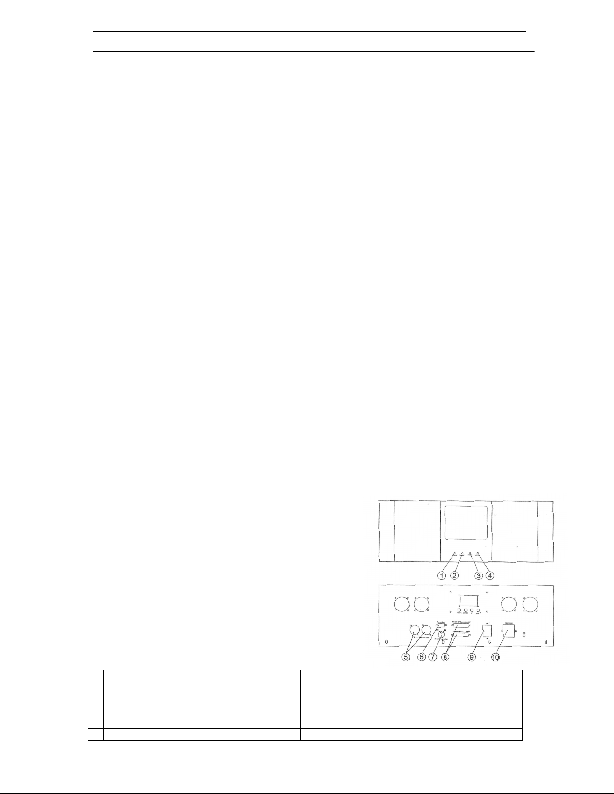
Using the laser
Make sure the correct voltage is used. Connect mains.
Connect an emergency switch to the 9-pin conector on the
backside (pins 1, 2). If you do not wish to connect an
emergency switch, connect the 9-pin plug. Depending on
the mode selected (see below), laser light should come
out of the opening on the front panel – be careful.
1 Power LED 6 Remotelock: connect emergency switch. If no
emergency switch is connected use the 9 pin plug.
2 Operation LED: controlboard working 7 Security switch: Laser on/off
3 DMX LED: DMX connected 8 ILDA connector in/out
4 ILDA LED: ILDA connected 9 Power switch: power on/off
5 DMX in/out 10 Power: connect to mains
Page 4

User manual: RS-400G
Rev: 09/2009
P
age 4 of 8
Control panel
• MODE: select mode, or go up in menu
• ENTER: confirm changes, or go down in menu
• UP/ DOWN: change DMX address
Operating modes:
Automatic mode: built-in patterns are displayed
Music active: laser is controlled from built-in microphone
“DMXAddr“: DMX512 mode-. Here you can change the DMX address:
“Open“: change address
“Up“ & “down“: increase/decrease address
“Save“: save new address
“LCD display memory function“: save settings automatically.
ILDA mode
When an IDLA compatible interface is connected to the laser, the laser is automatically
switched to ILDA mode. Output is then controlled from a PC running software.
The laser uses pins 4 and 17 of the IDLA signal to detect the presence of an ILDA interface.
Further information can be found in the software manual.
1 Operation LED
2 Working LED: controlboard working
3 DMX LED: DMX connected
4 ILDA LED ILDA connected
5 DMX In/Ou
Please note: the scanners are set to a scanspeed of ca. 22000 PPS at ca. 30°
scanangle. If you increase the scanspeed, first reduce the scanangle (image size). Otherwise
you may damage the scanners! When using with different scanspeed/scanangle
readjustment of the scanner drivers may be necessary, if in doubt, contact your dealer.
DMX mode
Channel
DMX
512
value
Func
tion
1 blue 0~63 Auto-Music Mode (Ch 1&2 valid)
64~127 Auto-mode (Ch 1&2 valid)
128~191 Music-edit mode (All channels valid)
192~255 Manual mode (All channels valid)
0~63 No Beam
64~127 Single colour laser: Strobe
Multicolour: colours
128~192 Single colour: Fluxion blanking
Multicolor: Colour change
2
Colour
193~255 On
0~42 Pattern group
1
43~85
Pattern group
2
86~128
Pattern group
3
129~171
Pattern group
4
172~214 Pattern group
5
3
Pattern group
215~255
Group 6 cartoons
4 Pattern
0~255
32 patterns
5 Speed
0~255
slow to fast
0~63 No function
64~127 Rotate horizontally
128~191 Rotate vertically
6
Rotation
192~255 Rotate h. & v.
0~63 No function
64~127
Rotating
7 Dot rotation
192~255
Rotating & Dotting
0~63
No function
64~127 Move horizontally
128~191 Move vertically
8 Move
192
~255 Move h. & v.
Page 5

User manual: RS-400G
Rev: 09/2009
P
age 5 of 8
0~63 No function
64~127 Extend horizontally
128~191 Extend vertically
9 Extend
192~255 Extend h. & v.
0~85 No functi
on
86~169 Small to large
10 Zoom
170~255 Large to small
11 Drawing speed
0~255
slow to fast
12 Scan speed
0~255
slow to fast
13 Colour
speed 0~255
slow to fast
0 Original size
14 Size
1
~255 Small to large (120 = original)
Maintenace / cleaning
Always disconnect from mains before cleaning/opening the laser. You can open the device
by removing the top: remove the mounting bracket (4 quick locks), the 5 Philips screws, and
the eye bolt.
Regularly clean the interior from dust, especially ensure operation of the fans. To clean the
mirrors, ideally use acetone and lens cleaning paper (fold paper to get an edge with which to
clean the mirrors). If not available, you can also use window cleaner, and a paper towel. Be
careful, even light scratches reduce the output power of the laser; always clean with strokes
in one direction, to minimize the effect of scratches. Mirrors need cleaning, when a “halo” is
noticeable around the beam, or an unusual high amount of diffuse light can be seen inside
the device.
When fog fluid condenses in the device, clean all traces, and rearrange the position of hazer
and/or laser.
Technical specifications
•
Output power: typical: 400mW, guaranteed: 300mW 532nm grün
•
Lasersources: aircooled DPSS laser
•
Laser class: 3b
•
Modes: ILDA, DMX 512, auto, music active
•
ILDA: 25pin ILDA standard Sub-D shaped 25pin connector
•
Galvos: 50k scanspeed
•
DMX 512: 14 channels
•
Patterns: 160
•
Scanangle: set to ca. 40° optical (60° max)
•
Beam: ca. 3mm/1mrad
•
Accessories: power cable, key switch, interlock plug, manual, safety cord
•
The laser comes in a flightcase.
•
Input voltage: AC 100~120V or 200~240V switchable 50/60Hz
•
Power consumption: 120W
•
Operating temperature: 10-35°C
•
Size: 550 x 320 x 310mm (W x D x H)
•
Weight: 15kg Laser, total: 28kg (with flightcase)
Change scanner
1. Unscrew UK M6 screws and disconnect signal cable.
2. Loosen M4 x 10 screw and remove galvo.
3. Insert galvo, reconnect and fix signal cable.
4. Rotate galvo to centre projection. Fix galvo.
Adjustable mirror mounts
Page 6

User manual: RS-400G
Rev: 09/2009
P
age 6 of 8
1. Loosen setscrews, then adjust with X/Y
adjustable screws. Make sure beam is
centered on scanner mirrors.
2. Adjust Z-screw simultaneously.
3. Tighten setscrews.
4. When combining beams (RGY/RGB laser),
first make sure the beams are (roughly) on
the same spot on the mirrors/dichros. Then
use a test pattern (e.g. rectangle) to do fine
adjustment. For adjustments, always turn
output power down (if possible).
Troubleshooting
Problem Possible reason Damaged part Replacement
Fuse blown Fuse 09-00-3001-01 No power
Power supply defective +-24V 16-03-0039-00
Microphone defective Microphone 16-03-0001-00
Control board defective Control board 26-2A-LT12V2-00
Potentiometer defective Potentiometer 04-03-0104-01
Music mode not working
CPU defective IC 00-89C516RD-00
Scanner defective Galvo 15-01-2215-00
CPU defective IC 00-89C516RD-00
Control board defective Control PCB 26-2A-LT12V2-00
Power supply defective +-24V 16-03-0039-00
X and/or Y axis no
deflection
Scanner driver board defective Scanner driver board 26-2A-6800A-00
Lenses / mirrors dirty Clean with alcohol
Laser diode defective Laser diode Inquire
Control board defective Control board 26-2A-LT12V2-00
Laser dark or dim
Configuration / wrong mode Check configuration (see
paragraph control panel)
Configuration / wrong mode Check configuration (see
paragraph control panel)
Control board defective Control PCB 26-2A-LT12V2-00
Power supply defective +-24V 16-03-0039-00
Display board defective Display 26-2A-YX2012DI-00
No output
Pins 4 and 17 of the ILDA signal
not connected
See below
Laser does not switch to ILDA mode:
• The interface does not connect pins 4 and 17 of the IDLA signal. See interface manual
• The cable does not connect pins 4 and 17. Use a cable that connects pins 4 and 17.
• Use an adapter, that connects pins 4 and 17 (Interlock).
ILDA signal
Pin out of the standard ILDA signal:
1 Scanner X+ -10V..+10V 14 X- +10V..-10V
2 Scanner Y+ -10V..+10V 15 Y- +10V..-10V
3 Intensity/Blanking+ 0V..+2.5V 16 Intensity/Blanking- 0..-2.5V
4 Interlock A 17 Interlock B
5 Red+ 0..2.5V 18 Red- 0..-2.5V
6 Green+ 0..2.5V 19 Green- 0..-2.5V
7 Blue+ 0..2.5V 20 Blue- 0..-2.5V
8 – 12 Not used 23-24 Not used
13 Shutter +5V, max. 20 mA 25 GND Signal ground
Page 7

User manual: RS-400G
Rev: 09/2009
P
age 7 of 8
Technical diagram
Schematic, not all colours may be present in the actual laser, depending on the model of the laser.
Please note
This device has left our premises in absolutely perfect condition. In order to maintain this
condition and to ensure a safe operation, it is absolutely necessary for the user to follow the
safety instructions and warning notes written in this user manual.
Laserworld cannot be made liable for damages caused by incorrect installations and unskilled
operation!
For service please contact your dealer, or see http://en.laserworld.com/en/reclamation-service.html
Page 8

User manual: RS-400G
Rev: 09/2009
P
age 8 of 8
EU-declaration of conformity
We hereby confirm that the following device
Laserworld RS-400G
complies with the essential safety requirements, laid down in the regulations of the
committee to assimilate the provisions of law of all participating EU states on the
electromagnetic compatibility (89/336/EWG) and with the requirements relating to the Low
Voltage Directive (LVD 2006/95/EG) was based on the following standards:
DIN EN 61000-3-2:2000 + A2: 2005
DIN EN 61000-3-3:1995 + A1: 2001
Furthermore, the device is verified in correspondence to the laser class regulations DIN EN
60825-1, if properly set up according to the upper mentioned laser safety regulation.
After installing the device, an inspection and official approval is indispensable for the overall
setup. The inspection must follow the european guidelines EN 60825-1 and corresponding
regulations for the prevention of accidents BGV-B2.
This declaration is executed on behalf of the Laserworld RS-400G manufacturer
Laserworld (Switzerland) AG
Oberstrasse 1
8274 Tägerwilen
SWITZERLAND
Authorized person:
Supervisory board Ms Rhea Gössel
place of business: 8274 Tägerwilen / SWITZERLAND
company number: CH-440.3.020.548-6
Commercial Registry Kanton Thurgau
www.laserworld.com
info@laserworld.com
representative according to EMVG:
Cleantech Europe GmbH
Managing Director: Thomas Schulze
Fürkhofstr. 5
81927 München / DE
 Loading...