

Page 1
1
LASER SOUND
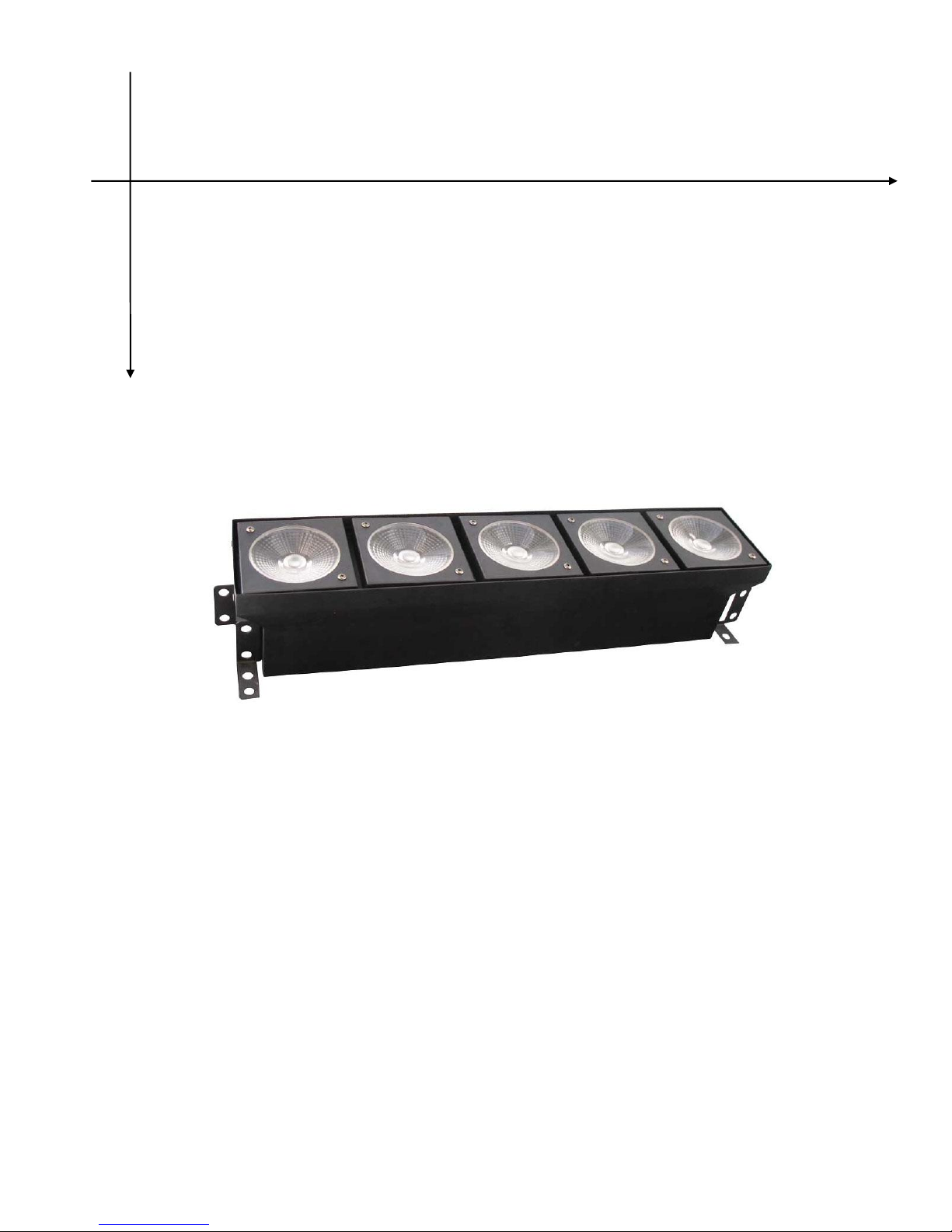
LED Matrix
DR-E01 5X15W RGBW 4IN1
USER MANUAL
Ver1.0
Page 2

2
Table of contents
1. Before you operating
···············································
3
1.1 Packing list···························································································3
1.2 Unp a ck in g in st ru ct io ns ··························································3
1.3 AC Po wer ··························································································· 3
1.4 Safety instructions············································································· 3
2. Introduction
······························································
4
2.1 Features································································································ 4
2.2 DMX ch an ne l··················································································4
3. Setup
·······································································
5
3.1 Fi x ture li n kin g ·················································································5
Dat a ca bl in g ····················································································· 6
DMX dat a ca b le ·············································································· 6
3-Pin to 5-Pin conversion chart························································6
3.2 Setting up a DMX serial data link···················································· 6
3.3 Setup······································································································· 7
4. Operating instructions··············································· 7
4.1 Navigating the control panel ·························································· 7
4.2 Men u ma p ·························································································· 7
4.3 Use r con f igurat io ns ····································································· 8
Set-up 1pcs light`s menu mode(Auto-running)·······························8
Setup DMX mode··················································································8
4.4 DM X ch an ne l va lu es ·································································· 9
5. Technical specifications··········································· 12
Page 3
3
Warning! Confirm the voltage to select switch which can be
matched the circuit with the light. If it is different from the supply
power and light, it will damage the light! All the light must be
connected the earth, not all the lights have the switch to be
selected.
Please connect the correct voltage!
1. Before you operating
1.1 Packing list
Product name
quantity
LED Matrix Light
1 pcs
Power -cable
1 base
1.2 Unp ac ki n g in st ru ct io ns
When you get this product, please take it from carton carefully to
make sure whether all the accessories are in and damaged or not
When you find that there are any parts or wrong sign with the carton,
or non-operation, please inform us and to keep the carton and
shipping bill completely.
1.3 AC Po we r
Please check the manual book before you operate the light. The
rating current of the light listed which shows the average
current-consume under the normal circumstances.
All the lights must be offered shoot-through circuit, it could not be
connected dimmer circuit, although the dimmer channels are
completely for 1-100% switch.
Before the light’s working, please confirm the correct voltage.
1.4 Safety instructions
Page 4
4
Please read these instructions carefully, it includes important
information about the light’s installation, usage and maintenance of
this product.
Please confirm the same voltage to the light.
The light could not be water-proof, it only allow to be used in door.
Don’t expand the light in wet or rain day, to avoid fire or damaged
light.
Please confirm there is no flammable material around the light.
The light must be set up the ventilating place. The distance is ≥
51cm around approach material. To check the air passage is OK at
any time.
The Maximum temperature is ≤40℃(104℉).
When the lights has problems, please stop to use to contact the
supplier. Don’t repair it by yourself!
Don’t connect by a dimmer.
To confirm the power wire is straight and non-damaged. Don’t pull it
directly.
Don’t look at the bulb when the light is working to avoid any hurt.
2. Introduction
2.1 Features
8 or 24 DMX channels.
RGBW LED light source,(R5,G5,B5,W5)
life long is 50000-10000 hours.
Variable electronic dimmer(0-100%).
Strobe:0-16Hz
Control mode:Auto,music,DMX512 mode
Beam angle:30°
Cool:Fan cooling
2.2 DMX cha n ne l
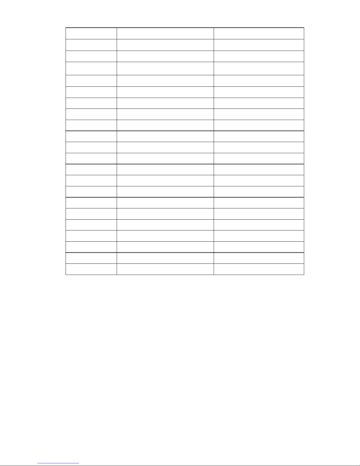
Channel
24CH
8CH
1
Dimmer
Dimmer
2
Strobe
Strobe
Page 5
5
3
Performance Function
Performance Function
4
Performance Speed
Performance speed
5
Red(the first led)
Red(ALL)
6
Green(the first led)
Green(ALL)
7
Blue(the first led)
Blue(ALL)
8
White(the first led)
White(All)
9
Red(the second led)
10
Gree(the second led)
11
Blue(the second led)
12
White(the second led)
13
Red(the third led)
14
Green(the third led)
15
Blue(the third led)
16
White(the third led
17
Red(the fourth led)
18
Green(the fourth led)
19
Blue(the fourth led)
20
White(the fourth led)
21
Red(the fifth led)
22
Green(the fifth led)
23
Blue(the fifth led)
24
White(the fifth led)
Note: *When the channel is opening, please confirm the channel
1stis phase-in.
3. Setup
3.1 Fi xt ur e li nk in g
When you control the light’s master/slave or DMX 512 signal
agreement, the lights can be connected by signal wire which the
distance is ≤500m,The maximum connect lights are 32pcs more or
less, and adapt DMX light pair to segregate the signal zoom
equipment, in order to protect the light’s signal won’t be interrupted by
other signal. Moreover, it won’t affect by the signal wire’s length
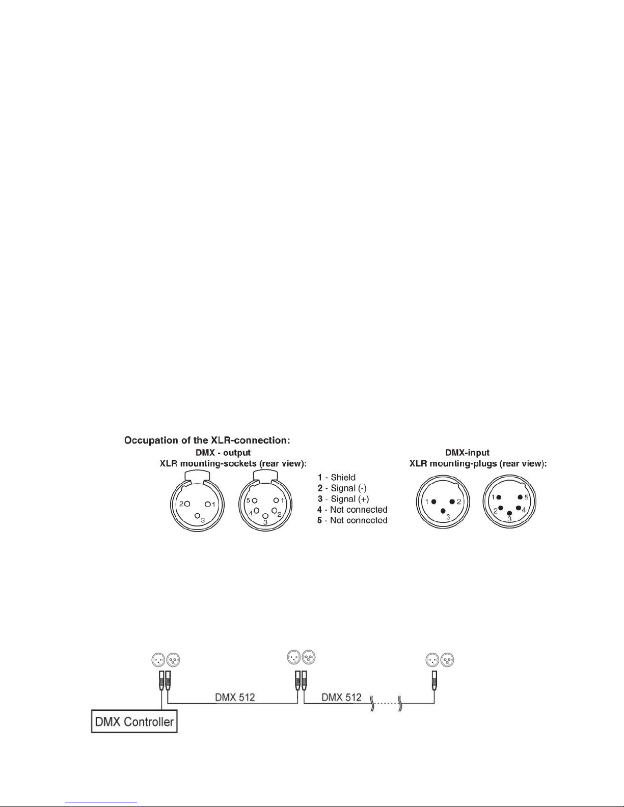
Dat a co nn ec t
Page 6
6
Data cable is connected by DMX data wire, and XLR. Please use
hi-quality data cable signal wire, it won’t be interrupted by magnetic.
Cha ra ct er is ti cs of DM X da t a cab l e
2 conductors’ double tree lace and shield.
The maximum capacitance of the conductors-30 pF/ft.
The maximum capacitance of the conductor and shield -55 pF/ft.
The maximum resistance is 20 ohms/1000ft.
The nominal impedance 100-140 ohms.
DMX opt coupler segregate signal zoom equipment’s 3 pin(5 pin) XLR
plug.
Cable wire’s adapter:
The two sides of signal cable wire is consisted of 1 pair female and
male 3 XLR plug, which is correspond the lights or DMX controller,
3-P in t o 5- Pi n co nv ersi o n cha r t
Note! If you use a controller with a 5 pin DMX output connector. you
will need to use a 5pin to 3 pin adapter
CHAUVET Model No:DMX5M. or DMX 5F
The chart below details a proper cable conversion:
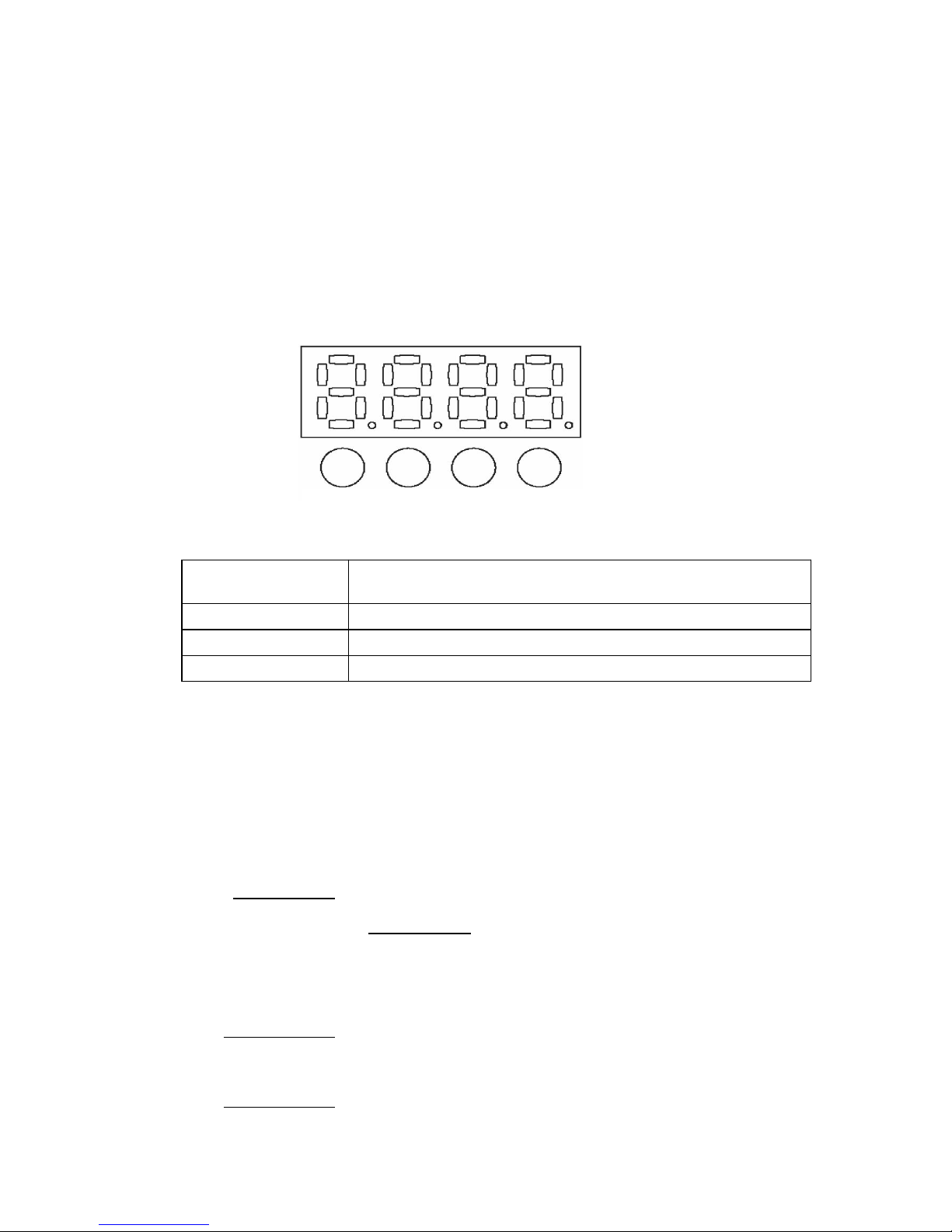
3.2 Setting up a DMX signal connect
As following pictures show, please connect the first light to the signal
cable which is with XLR by DMX controller, then, connect light in
series.
Page 7
7
The light must be set up the ventilating place. To confirm there is
nothing to hinder the heat dissipation place. When the light is hanged,
please choose a safety wire.
4. Operating instructions
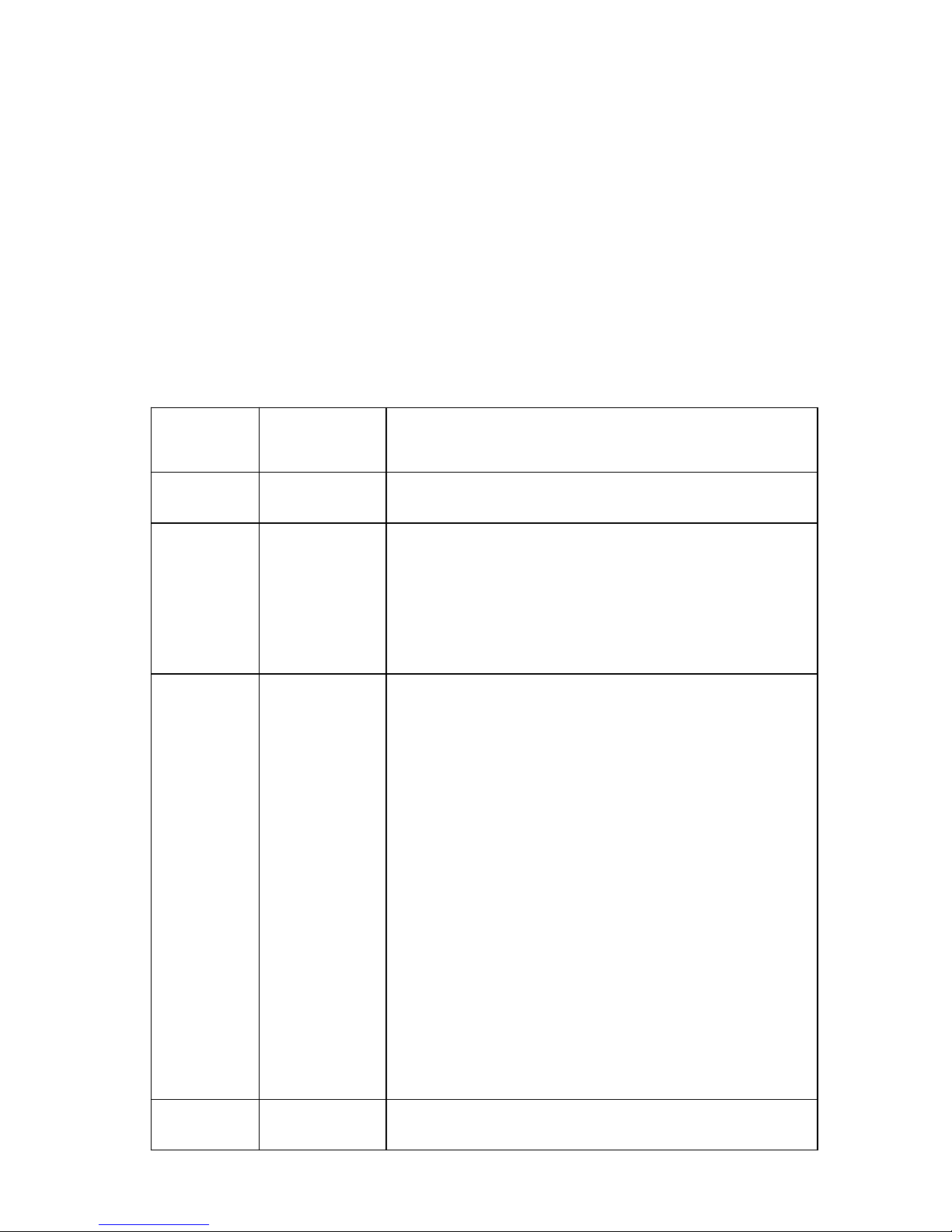
4.1 Menu configure
There are 4 buttons located in the bottom of the LED digital display
when you check the menu configure of the bottom of light. Show as
follow:
Note: Please choose ”ENTER” return to the main menu to
save the address code or mode after you set up. When the
light is lighting, the display of the address code or mode is
same as the last time when you operated.
4.2 Me nu fun ctio n m ap
(Main menu)
|
(1stclass option)
|
(2ndclass option)
Add(Address code setting)*
|
A.001
|
……
|
A.512
FLAS (Strobe setting)
Button
Function
<ENTER>
Each operation to be confirmed
<DOWN-<UP>
Down-Up
<MENU>
menu option
MENU
UP
DOWN
ENTER
Page 8

8
|
F0XX**(the total speed of strobe to be adjusted)
|
FrXX(To adjust red brightness separately)
|
FgXX(To adjust green brightness separately)
|
FbXX(To adjust blue brightness separately)
|
FAXX(To adjust white brightness separately)
Lrgb(Adjust separately Led brightness)
|
LrXX(To adjust red brightness separately)
|
LgXX(To adjust green brightness separately)
|
LbXX(To adjust blue brightness separately)
|
LAXX(To adjust white brightness separately)
CHAS(built in program)
|
C001-C010(fast to slow perform )
CHSE(channel setting )
|
CH24(DMX512 CH 24)
|
CH08(DMX512 CH 8)
FACT(Restore factory settings)
|
FA00-01 FA01 restore factory setting after pressing “ ENTER”
(factory setting is DMX mode)
Note:* “Add”, of “.” Which should show as flicker ,non-flicker means
no signal or wrong signal.
***Shade: Red from bright to be off, then, green from bright to be off,
then, blue from bright to be off, then, Red from bright to be off…
****Change: Red bright, red be off, green bright, green be off, blue
bright, blue be off, red bright…
XX” Value:“01-10”.
4. 3 Use r co nf ig ur at io ns
Set-up 1pcs light`s menu mode (Auto-running)
.Press the MENU, such as the picture 4.2 shows the menu function
.Use the UP/DOWN buttons to choose the right one to confirm.
To set Master-slave mode
.Press the MENU, same as picture 4.2 shows the menu function
Master: Set any one of lights to auto、sound or strobe control mode
Slave: Set them to DMX mode and their address code to1.
Page 9
9
Notes:Each Master-slave group can be one and only light in master,
ensure lights under this group without connection with any DMX controller.
To set D MX m od e
The light can connect to the DMX controller to receive its signal
indication, which control by DMX controller. DMX value is referenced
by “4. 4 DM X ch an n el v al ue s” .
4.4 DMX cha n ne l val u es
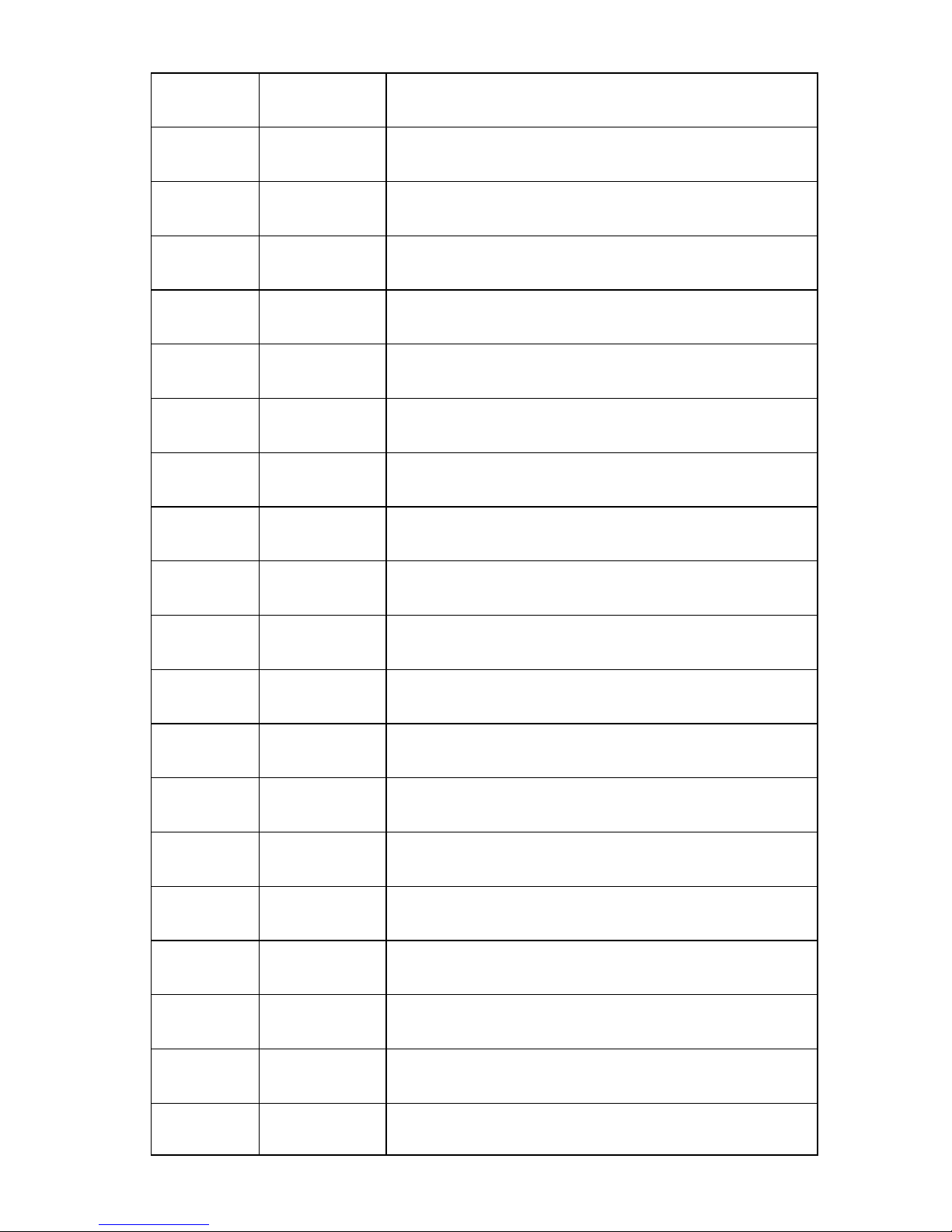
24 D M X c h a n n e l s:
Channel
Value
Function
1
0-255
Dimmer
0-100%
2
0-10
11-30
31-200
201-250
251-255
Strobe
Shut
Neutral
Strobe with increase speed
Random Strobe with increase speed
Neutral
3
0-15
16-31
32-47
48-63
64-79
80-95
96-111
112-127
128-143
144-159
160-175
176-191
192-207
208-223
224-239
240-255
Performance Function
Neutral
Red
Green
Blue
White
Red/Green
Red/Blue
Red/White
Green/Blue
Green/White
Blue/White
Red/Green/Blue
Red/Green/White
Green/Blue/White
Blue/Red/White
Red/Green/Blue/White
4
0-255
Performance Speed
Fast to slow
Page 10
10
5
0-255
Red(the first led)
0-100%
6
0-255
Green(the first led)
0-100%
7
0-255
Blue(the first led)
0-100%
8
0-255
White(the first led)
0-100%
9
0-255
Red(the second led)
0-100%
10
0-255
Green(the second led)
0-100%
11
0-255
Blue(the second led)
0-100%
12
0-255
White(the second led
0-100%
13
0-255
Red(the third led)
0-100%
14
0-255
Green(the third led)
0-100%
15
0-255
Blue(the third led)
0-100%
16
0-255
White(the third led
0-100%
17
0-255
Red(the fourth led)
0-100%
18
0-255
Green(the fourth led)
0-100%
19
0-255
Blue(the fourth led)
0-100%
20
0-255
White(the fourth led)
0-100%
21
0-255
Red(the fifth led)
0-100%
22
0-255
Green(the fifth led)
0-100%
23
0-255
Blue(the fifth led)
0-100%
24
0-255
White(the fifth led)
Page 11
11
0-100%
8 D M X c h a n n e l s :
Channel
Value
Function
1
0-255
Dimmer
0-100%
2
0-10
11-30
31-200
201-250
251-255
Strobe
Shut
Neutral
Strobe with increase speed
Random Strobe with increase speed
Neutral
3
0-15
16-31
32-47
48-63
64-79
80-95
96-111
112-127
128-143
144-159
160-175
176-191
192-207
208-223
224-239
240-255
Function
Neutral
Red
Green
Blue
White
Red/Green
Red/Blue
Red/White
Green/Blue
Green/White
Blue/White
Red/Green/Blue
Red/Green/White
Green/Blue/White
Blue/Red/White
Red/Green/Blue/White
4
0-255
Performance speed
Fast to slow
5
0-255
Red(ALL)
0-100%
6
0-255
Green(ALL)
0-100%
7
0-255
Blue(ALL)
0-100%
8
0-255
White(ALL)
0-100%
Page 12

12
5. Specifications
Model number
CLEP5015M
Input Voltage
AC100V -240V, 50Hz/60Hz
Lamp resource
5pcs 15W RGBW 4IN1 CREE LED
Control model
Auto,sound,DMX512 signal
Max temperature
104°F(40°C)
Data input/output
3pin XLR-connection、anode socket
LENS angle
30°
Outside size
625x155x130mm
N.W
3.65kg
 Loading...