

Laserscale BL57-RE Instruction Manual

Scale Unit / Maßstabseinheit
BL57-RE
Read all the instructions in the manual carefully before use and strictly follow them.
Keep the manual for future references.
Lesen Sie die ganze Anleitung vor dem Betrieb aufmerksam durch und folgen Sie beim
Betrieb des Geräts den Anweisungen. Bewahren Sie diese Bedienungsanleitung zum
späteren Nachlesen griffbereit auf.
LASERSCALE / LASERSCALE
Instruction Manual / Bedienungsanleitung

BL57-RE
Safety Precautions
Magnescale Co., Ltd. products are designed in full consideration of safety. However, improper
handling during operation or installation is dangerous and may lead to fire, electric shock or
other accidents resulting in serious injury or death. In addition, these actions may also worsen
machine performance.
Therefore, be sure to observe the following safety precautions in order to prevent these types of
accidents, and to read these “Safety Precautions” before operating, installing, maintaining, inspecting, repairing or otherwise working on this unit.
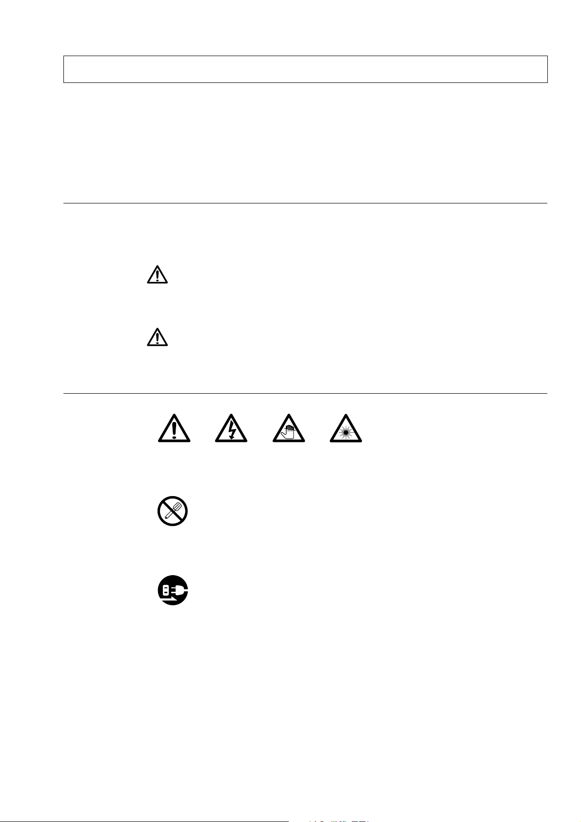
Warning indication meanings
The following indications are used throughout this manual, and their contents should be understood before reading the text.
Warning
Failure to observe these precautions may lead to fire, electric shock or other accidents resulting
in serious injury or death.
Caution
Failure to observe these precautions may lead to electric shock or other accidents resulting in
injury or damage to surrounding objects.
Symbols requiring attention
CAUTION ELECTRICAL
Symbols prohibiting actions
DO NOT
DISASSEMBLE
Symbols specifying actions
UNPLUG-
GING
SHOCK
FINGER JAM
LASER BEAM
BL57-RE
(E) (1)
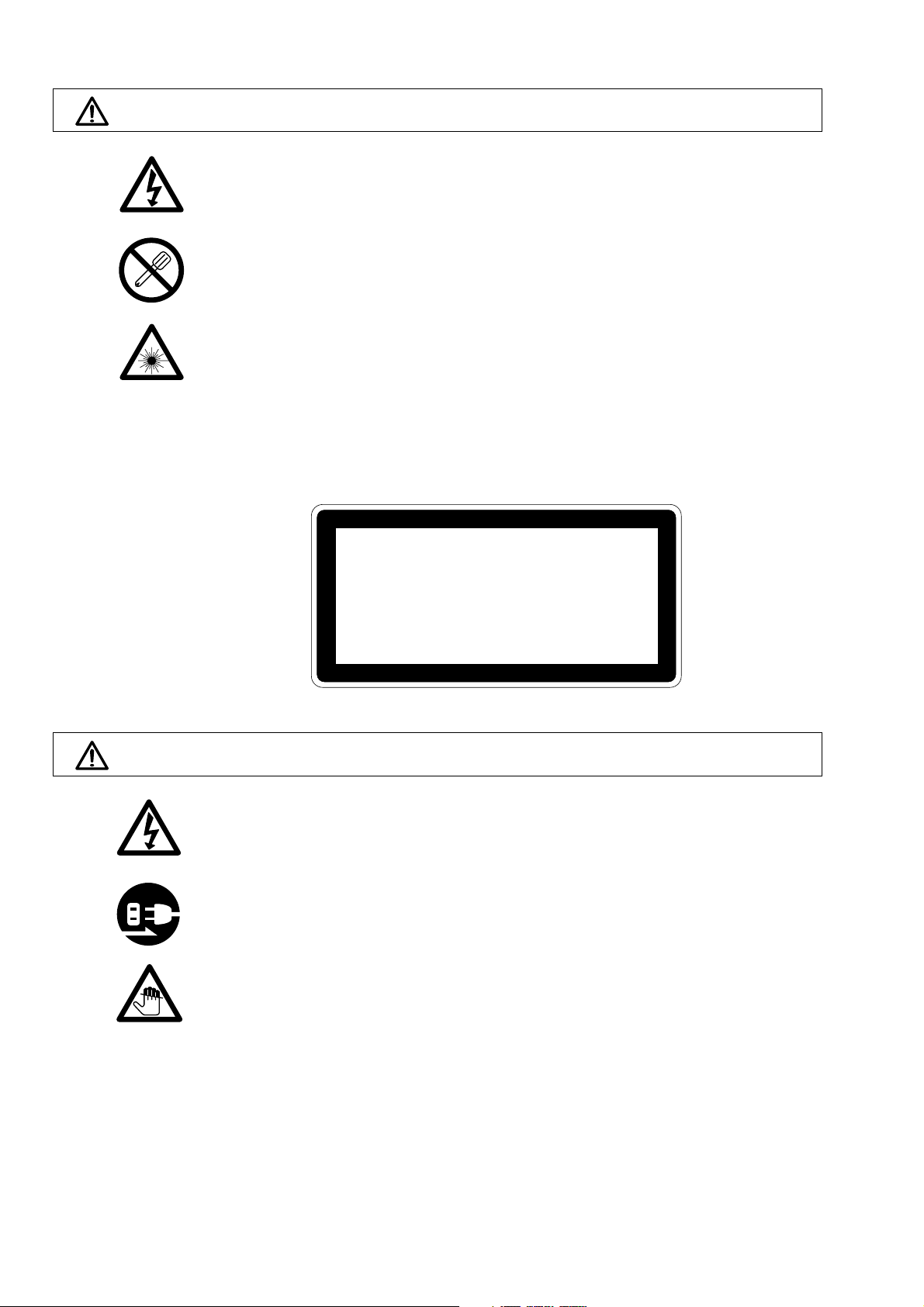
Warning
• Do not use this unit with voltages other than the specified supply voltages as this may
result in fire or electric shock.
• Do not perform installation work with wet hands as this may result in electric shock.
• Do not disassemble or modify the unit as this may result in injury or damage the
internal circuits.
• This device is a class 1 laser product using a semiconductor laser with wavelength of
790 nm that is outside the visible range. The maximum output of the laser is 6 mW
(class 3B).
• Although the laser beams emitted from the head interior are invisible to the eye, they
are hazardous to the human body. Therefore, never disassemble the scale unit, or try
to look into it from the sealed section of the scale unit. Also, never insert foreign objects into the sealed section of the scale unit.
CLASS 1 LASER PRODUCT
Caution
LASERSCHUTZKLASSE 1 PRODUKT
TO EN 60825
• Be sure to check the machine and device conditions to ensure work safety before
working on the machine.
• Be sure to cut off the power supply and other sources of drive power before working
on the machine. Failure to do so may result in fire or accidents.
• When turning on the power supply or other sources of drive power to operate the
machine, take care not to catch your fingers in peripheral machines and devices.
(2) (E)
BL57-RE
CAUTION
5V
Magnescale Co
CT COCO
ES WIWI
TH
21
CFR
J
BLE
OF
E.
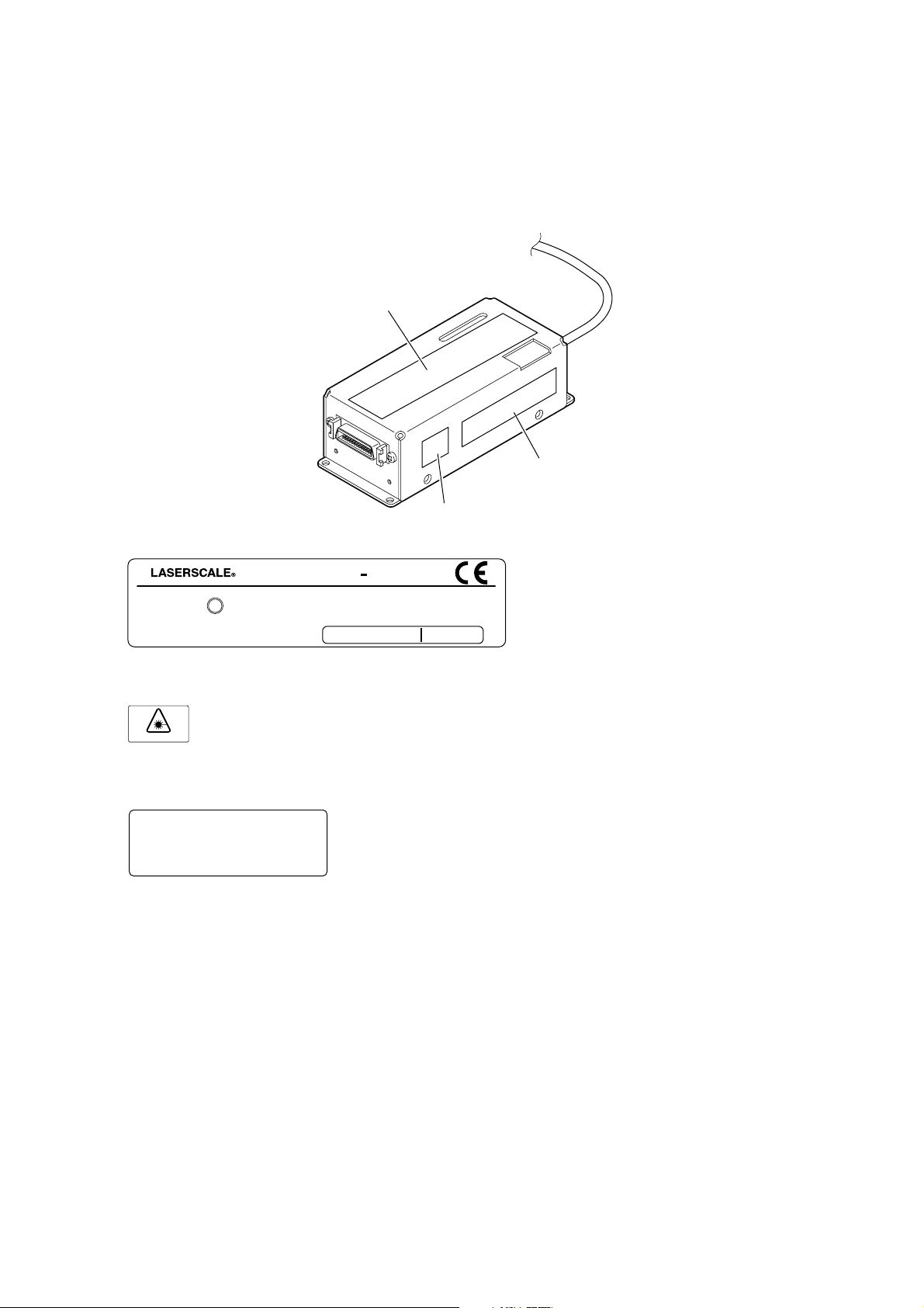
Use of controls or adjustments or perfomance of procedures other than those specified herein may result in hazardous radiation exposure.
q
e
w
q Specification/DHHS label
CERTIF I CA T ION
PR OD UCT
A PP L I CACABLE
J
POPOWE R R SUSUPP LY : DC
Magnescale Co
., Ltd.
w Laser Danger label
See Manual
e FCC label
THIS CLASS A DIGITAL DEVICE COMPLIES WITH PART 15 OF THE FCC
RULES AND THE CANADIAN ICES-003.
OPERATION IS SUBJECT TO THE FOLLOWING TWO CONDITIONS: (1) THIS
DEVICE MAY NOT CAUSE HARMFUL INTERFERENCE. AND (2) THIS DEVICE
MUST ACCEPT ANY INTERFERENCE RECEIVED. INCLUDING INTERFERENCE
THAT MAY CAUSE UNDESIRED OPERATION.
CET APPAREIL NUMERIQUE DE LA CLASSE A EST CONFORME A LA NORME
NMB-003 DU CANADA.
MP L I ES
AT T D AT E E OF
3-188-177-22
BL57
TH
D HH S S R ULULE S S 21
+
5V
MA NU F A CT U RE.
CFR
S UB CH A PTPTE R
MADADE E I N N JAPAPAN
BL57-RE
(E) (3)

Operating Precautions
• An antistatic cap is attached to the connector plug of the interface unit. Do not remove this cap until you are
ready to connect the peripherals.
After removing the static electricity proof cap, take care not to touch the connector pins as this might cause
malfunctions.
• Be sure to make all connections of the interface unit connector and the peripherals before switching the power on.
Never insert or pull out the connector when the power switch is on.
• Do not pull at the cable forcibly or bend it excessively. (Bending radius (inside) Static: 10 mm or more, immobile)
• Use the BL57-RE approximately 30 minutes after power is supplied to the unit, when the temperature of the
detector head reaches a stable state.
• The BL57-RE is a precision measuring instrument. Handle it with extreme care so that no excessive shock is
applied to it. For transport, be sure to pack it in the same way as it was packed at the time of purchase. Be sure
to always attach the antistatic cap to the connector.
Notes on installation
Take careful note of the following points when installing the scale unit to prevent noise and electromagnetic interference from other equipment.
• Do not pass the head cable and connection cable through the same duct as the power line.
• Install in a location that is at least 0.5 meters separated from sources of high voltage and large currents and
large power relays.
• Do not use the cable connecting the detector head to the interface unit in a location where it is likely to be
repeatedly subjected to a bending force (cable bear, etc.). In such a case, bend the cable connected to the
output connector on the interface unit.
Notes on attachment location
• Attach the scale in a location as near as possible to the workpiece and measurement object of the machine.
• Use this product in an environment with an ambient temperature of 0 to 40 °C.
Do not attach it to a location that is exposed to direct sunlight or warm air or near sources of heat such as motors.
This could adversely affect the accuracy.
• If using a water-soluble cutting fluid or other substances, ensure that there is adequate protection so that it does
not adhere to the scale.
• Never place objects on top of the attached scale, rest your elbows or feet on the scale when using it, or apply an
excessive amount of pressure to the scale.
Notes on storage
• Do not store in locations with high temperatures or high humidity.
This could have an adverse effect on scale performance. Store in a location that is as dry as possible.
General Precautions
When using Magnescale Co., Ltd. products, observe the following general precautions along with those given
specifically in this manual to ensure proper use of the products.
• Before and during operations, be sure to check that our products function properly.
• Provide adequate safety measures to prevent damages in case our products should develop malfunctions.
• Use outside indicated specifications or purposes and modification of our products will void any warranty of the
functions and performance as specified of our products.
• When using our products in combination with other equipment, the functions and performance as noted in this
manual may not be attained, depending upon operating environmental conditions. Make full study of the compatibility in advance.
(4) (E)
BL57-RE

[For U.S.A. and Canada]
THIS CLASS A DIGITAL DEVICE COMPLIES WITH
PART15 OF THE FCC RULES AND THE CANADIAN
ICES-003. OPERATION IS SUBJECT TO THE
FOLLOWING TWO CONDITIONS.
(1) THIS DEVICE MAY NOT CAUSE HARMFUL
INTERFERENCE, AND
(2) THIS DEVICE MUST ACCEPT ANY
INTERFERENCE RECEIVED, INCLUDING
INTERFERENCE THAT
MAY CAUSE UNDERSIGNED OPERATION.
CET APPAREIL NUMERIQUE DE LA CLASSE A
EST CONFORME A LA NORME NMB-003 DU
CANADA.
BL57-RE
(E) (5)

(6) (E)
BL57-RE

Contents
1. Overview ......................................................................... 1-1
1-1. Introduction .................................................................................................. 1-1
1-2. Main Features ............................................................................................... 1-1
1-3. Series Models ............................................................................................... 1-2
2. Names and Functions of Parts ..................................... 2-1
3. Mounting and Adjustment ............................................. 3-1
3-1. Mounting Precautions .................................................................................. 3-1
3-1-1. When Mounting .......................................................................... 3-1
3-1-2. Mounting Direction .....................................................................3-2
3-1-3. Mounting Requirements .............................................................. 3-2
3-2. Mounting Surface Preparations .................................................................... 3-3
3-3. Scale Mounting ............................................................................................ 3-5
3-4. Detector Head Mounting .............................................................................. 3-9
3-5. Signal Adjustment ...................................................................................... 3-10
3-5-1. Signal Adjustment Preparations ................................................ 3-10
3-5-2. Azimuth Adjustment ................................................................. 3-11
3-6. Completion of Mounting and Adjustment.................................................. 3-13
4. Interface Unit .................................................................. 4-1
4-1. Removing and Attaching the Interface Unit Cover ...................................... 4-1
4-2. Installing the Interface Unit .........................................................................4-1
4-3. Names of LEDs ............................................................................................ 4-2
4-4. MODE Switch ..............................................................................................4-3
4-4-1. Detailed Description of MODE Switches ................................... 4-4
4-5. Changing the Settings .................................................................................. 4-5
4-5-1. Changing the Direction ............................................................... 4-5
4-5-2. Changing the Resolution ............................................................. 4-5
4-5-3. Setting the Reference Point Output Signal Width .......................4-5
4-5-4. Adjusting the Reference Point .................................................... 4-6
4-5-5. Setting the Reference Point Output and Reference Point
Detection Direction ..................................................................... 4-7
4-5-6. Setting the Alarm Reset Mode .................................................... 4-8
5. Scale Signal Output ....................................................... 5-1
5-1. A/B Signal and Alarm Output Specifications
(For output formats F and G) ....................................................................... 5-1
5-2. Analog Output Specifications (For output format H) .................................. 5-2
6. Input/Output Connectors............................................... 6-1
6-1. Connectors.................................................................................................... 6-1
6-2. Connection Specifications ............................................................................6-3
6-2-1. A/B Signal Output Type ..............................................................6-3
6-2-2. Analog Output Type .................................................................... 6-5
6-2-3. Output Cable Length (For analog output only) ........................... 6-6
BL57-RE
7. Main Specifications........................................................ 7-1
(E) i

8. Dimensions ..................................................................... 8-1
8-1. Neoceram Models ........................................................................................ 8-1
8-2. Soda Lime Glass Models ............................................................................. 8-2
9. Trouble Prevention ......................................................... 9-1
ii (E)
BL57-RE

1. Overview
1-1. Introduction
The BL57-RE series is an open-type LASERSCALE with integrated detector containing a built-in reference
point. The interface unit is supplied with DC power at +5 V ±5 % for output of A/B and Z signals, or analog
and reference point signals.
1-2. Main Features
■ Resolution: A/B signal output type : 0.1/0.05, 0.02/0.01 µm
Analog output type : 0.4 µm
■ Head signal cycle of 0.4 µm allows the interpolation error to be disregarded
■ Optical integrated circuits employing the latest semiconductor technology are used to achieve a compact
and low-energy design
■ Theoretically not affected by changes in temperature, air pressure, or by atmospheric fluctuations and
uses low-expansion glass for enhanced measurement stability
■ Maximum speed: 3,000 mm/s (analog output)
BL57-RE
(E) 1-1
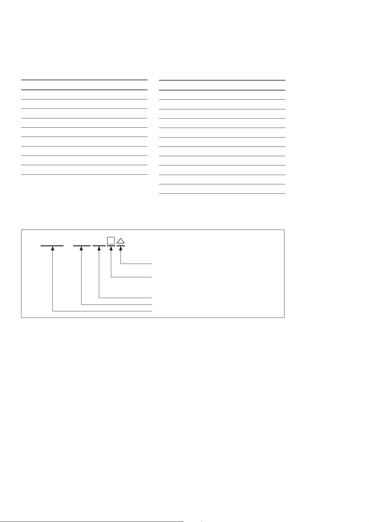
1-3. Series Models
Neoceram models Soda lime glass models
Model name Measuring length
BL57-003RE∗C 30 mm
BL57-006RE∗C 60 mm
BL57-011RE∗C 110 mm
BL57-016RE∗C 160 mm
BL57-021RE∗C 210 mm
BL57-026RE∗C 260 mm
BL57-031RE∗C 310 mm
BL57-036RE∗C 360 mm
BL57-041RE∗C 410 mm
Note:It is possible to use a special specification unit that
has a measuring length of between 420 and 660 mm.
Table 1-1
BL57−
***
RE
Model name Measuring length
BL57-006RE∗B 60 mm
BL57-016RE∗B 160 mm
BL57-026RE∗B 260 mm
BL57-036RE∗B 360 mm
BL57-046RE∗B 460 mm
BL57-056RE∗B 560 mm
BL57-066RE∗B 660 mm
BL57-076RE∗B 760 mm
BL57-086RE∗B 860 mm
BL57-096RE∗B 960 mm
BL57-106RE∗B 1060 mm
Note: It is possible to use a special specification unit that has
a measuring length of between 1070 and 1360 mm.
Scale material C : Neoceram
B: Soda lime glass
Output format F : A/B signal output (0.1/0.05 µm)
G: A/B signal output (0.02/0.01 µm)
H: Analog output (0.4 µm)
Open type (with reference point)
Measuring length (cm)
Model
Fig. 1-1
Examples
• BL57-026REGC : Neoceram 260 mm, Open type with reference point, A/B signal output (0.02/0.01 µm)
• BL57-006REFB : Soda lime glass 60 mm, Open type with reference point, A/B signal output (0.1/
0.05 µm)
• BL57-026REHB : Soda lime glass 260 mm, Open type with reference point, Analog output (0.4 µm)
1-2 (E)
BL57-RE

2. Names and Functions of Parts
Reference plate
Mounting screw
Plain washer
Scale clamp
Spacer
Scale
Head cable
Pan-head screw
Cable clamp
Detector
head
Interface unit
Fig. 2-1
BL57-RE
(E) 2-1

2-2 (E)
BL57-RE
3. Mounting and Adjustment
Follow the procedure below. (For details refer to the corresponding pages.)
3-1. Mounting Precautions....................................................................................................................... 3-1
3-1-1. When Mounting .................................................................................................................... 3-1
3-1-2. Mounting Direction ............................................................................................................... 3-2
3-1-3. Mounting Requirements ........................................................................................................ 3-2
3-2. Mounting Surface Preparations ........................................................................................................ 3-3
3-3. Scale Mounting................................................................................................................................. 3-5
3-4. Detector Head Mounting .................................................................................................................. 3-9
3-5. Signal Adjustment .......................................................................................................................... 3-10
3-5-1. Signal Adjustment Preparations .......................................................................................... 3-10
3-5-2. Azimuth Adjustment ........................................................................................................... 3-11
3-6. Completion of Mounting and Adjustment ...................................................................................... 3-13
3-1. Mounting Precautions
3-1-1. When Mounting
• The scale and the detector head are adjusted to each other. If using more than one scale unit, be sure that
the scale-head combinations have matching serial numbers.
• Consider the mounting position (Abbe error) and the environmental conditions (temperature, humidity,
vibration and dust) thoroughly.
• Do not lead the head cable through the same duct with the power cable. Also, do not bundle the head cable
and power cable together using a tie.
• Install in a location that is at least 0.5 meters separated from sources of high voltage and large currents
and large power relays.
• Do not use the cable connecting the detector head to the interface unit in a location where it is likely to be
repeatedly subjected to a bending force (cable bear, etc.). In such a case, bend the cable connected to the
output connector on the interface unit.
• Use this product in an environment with an ambient temperature of 0 to 40 °C.
Do not attach it to a location that is exposed to direct sunlight or warm air or near sources of heat such as
motors. This could adversely affect the accuracy.
• If using a water-soluble cutting fluid or other substances, ensure that there is adequate protection so that
it does not adhere to the scale.
• Set the maximum travel of the machine’s moving part shorter than that of the scale.
Scale’s max. travel = measuring length +10 mm/0.39" (5 mm/0.20" per each side)
(If the scale’s max. travel is exceeded, the scale unit signals will not be output and an error will occur.)
• For the scale unit, scale signal adjustment is necessary after mounting. When mounting the scale to the
machine, make sure that there is enough space for the adjustment. (See pages 3-3 to 3-13.)
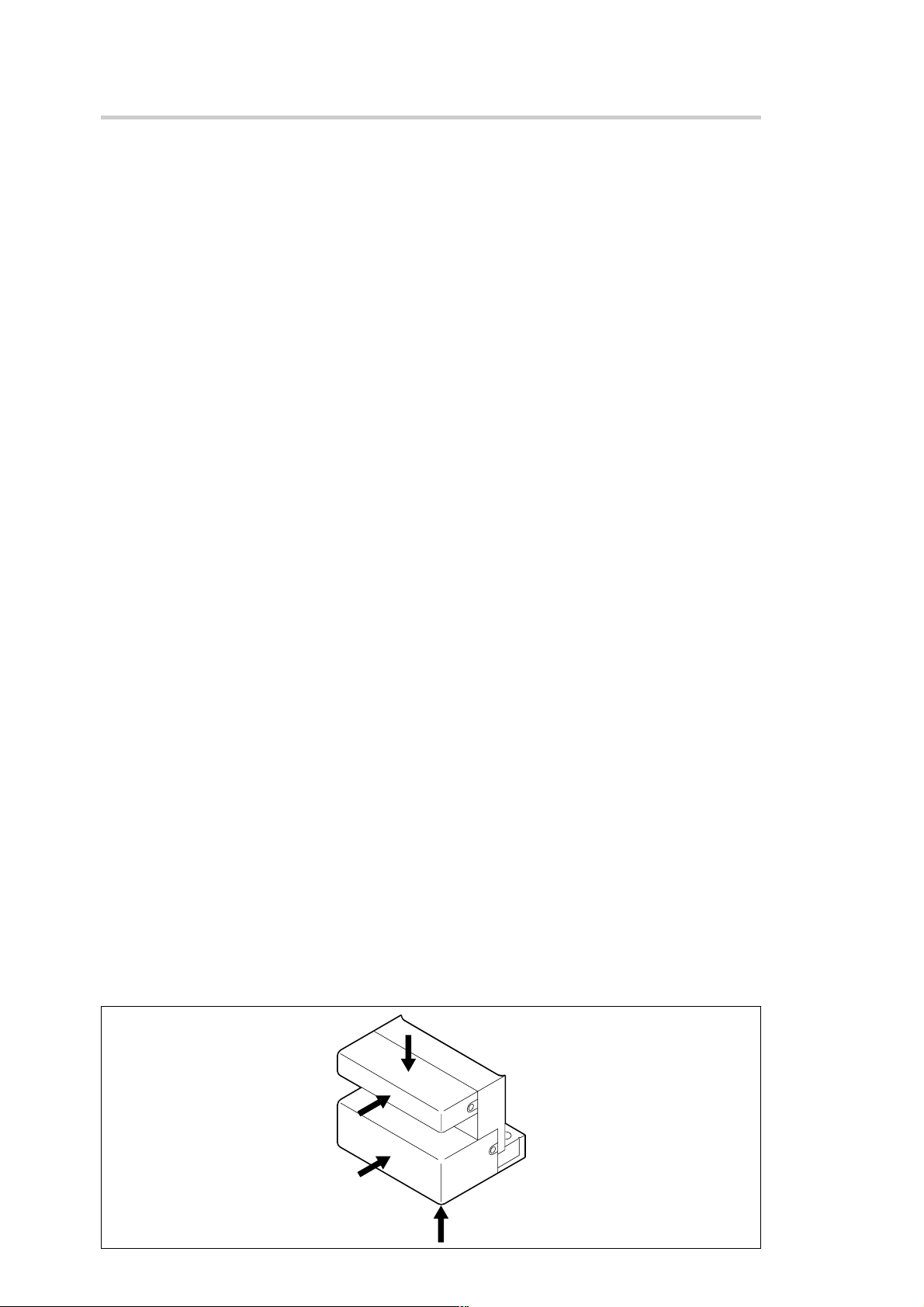
• When mounting and adjusting the detector head, do not touch the surface of the head cover indicated by
the arrows in the drawing below.
BL57-RE
Fig. 3-1
(E) 3-1

3-1-2. Mounting Direction
Mounting can be performed in the vertical or horizontal direction.
The mounting direction shown in the figure is recommended when mounting in the horizontal direction.
Upside
or
Downside
Fig. 3-2
3-1-3. Mounting Requirements
Measuring Instruments
• Electrical micrometer or lever type dial gauge ......................................................................................(1)
(one that can measure to an accuracy of 2 µm)
• Dial gauge stand .....................................................................................................................................(1)
• Oscilloscope ...........................................................................................................................................(1)
Capable of 2-quadrant X-Y display
Input sensitivity : DC 0.1 V/DIV
X-Y frequency band : 1 MHz or more
Tools
• Hex. wrenches: 3 mm.............................................................................................................................(1)
• Philips screwdriver No. 1 .......................................................................................................................(1)
• Philips screwdriver No. 0 .......................................................................................................................(1)
Miscellaneous
• Accessories ...................................................................................................................................... (1 set)
• Gauze ................................................................................................................................ (Small amount)
• Alcohol .............................................................................................................................. (Small amount)
3-2 (E)
BL57-RE
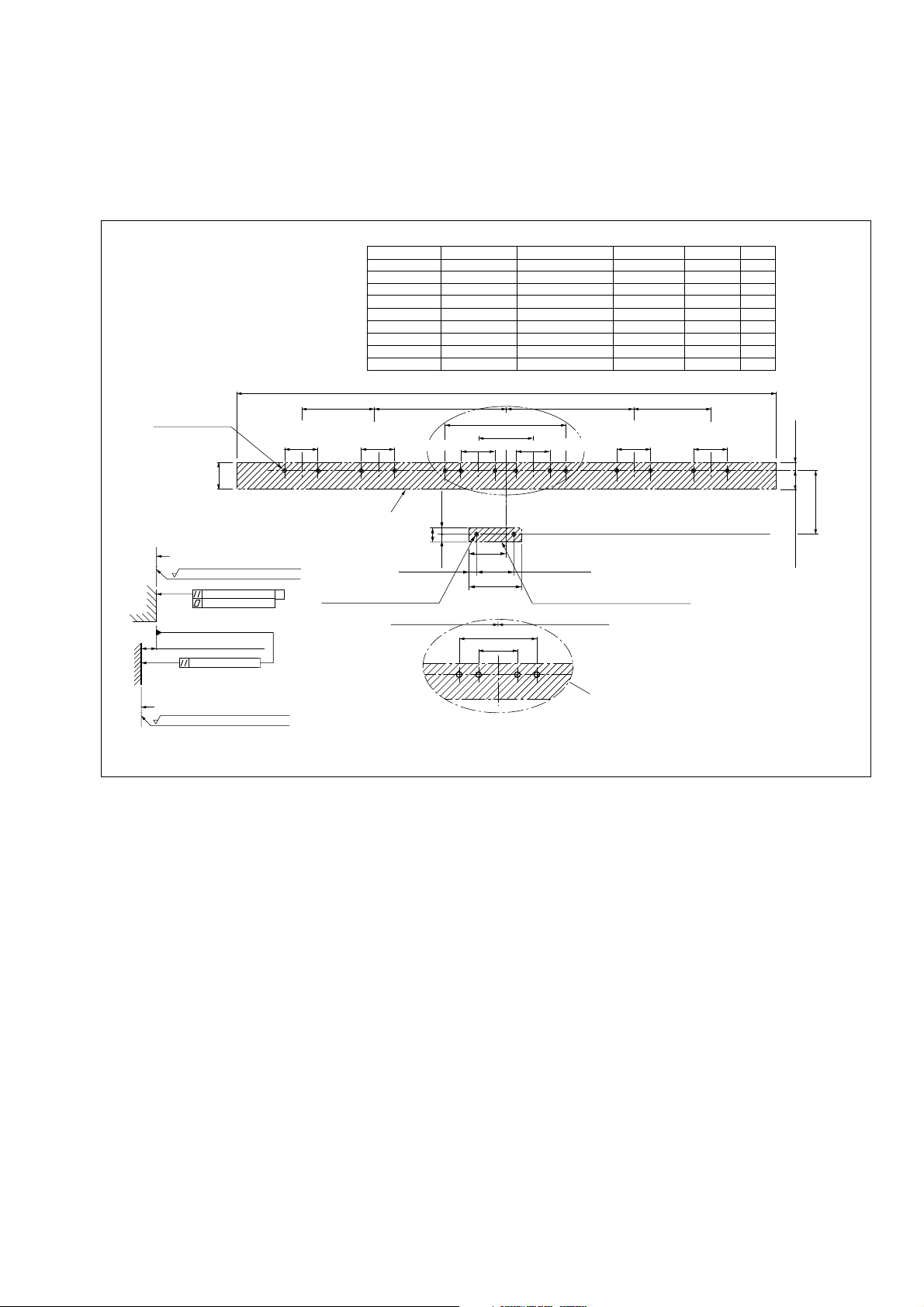
3-2. Mounting Surface Preparations
1. Check the mounting surface range (the shaded sections in the figure) and accuracy.
2. Check the accuracy of the mounting screw coordinates.
Neoceram models
depth: 6 (0.236")
P-M4
19.5 (0.768")
Scale mounting surface
Rmax = 6.3S (250 µinch)
0.01 (0.00039")
0.01 (0.00039")
18.4 ±0.2 (0.724" ±0.008")
0.02 (0.00079")
Detector head mounting surface
Rmax = 12.5S (500 µinch)
25 ±0.2
(0.984" ±0.008")
(0.984" ±0.008")
Scale mounting surface
M
2-M4 depth: 10 (0.394")
Model
BL57-003RE*C
BL57-006RE
BL57-011RE
BL57-016RE
BL57-021RE
BL57-026RE
BL57-031RE
BL57-036RE
BL57-041RE
25 ±0.2
L2
Measuring length
30 (1.181")
60 (2.362")
C
*
110 (4.331")
C
*
160 (6.299")
C
*
210 (8.268")
C
*
260 (10.236")
C
*
310 (12.205")
C
*
360 (14.173")
C
*
410 (16.142")
C
*
L1
66 (2.598") or more
96 (3.780") or more
146 (5.748") or more
196 (7.717") or more
246 (9.685") or more
296 (11.654") or more
346 (13.622") or more
396 (15.591") or more
446 (17.559") or more
L2
–
–
50 (1.969")
75 (2.953")
100 (3.937")
120 (4.724")
120 (4.724")
75 (2.953")
100 (3.937")
L1
L2 ±1 (0.039") L2 ±1 (0.039")L3 ±1 (0.039") L3 ±1 (0.039")
±
0.3 (3.465" ±0.012")
88
40 ±0.2 (1.575" ±0.008")
25 ±0.2 (0.984" ±0.008") 25 ±0.2 (0.984" ±0.008")
5
(0.197")
(10.5)
(5.5)
(0.217")
±
1 (0.039")
(0.413")
5.5
(1.102")
(0.217")
28
38
(1.496")
27 ±0.2
(1.063" ±0.008")
Detector head mounting surface
L2 ±1 (0.039")
25 ±0.2
(0.984" ±0.008")
(0.984" ±0.008")
50 ±0.3 (1.969" ±0.012 ")
25 ±0.2 (0.984" ±0.008")
For BL57-003RE*C, 011RE*C, 016RE*C,
C, 036RE*C, 041RE*C
021RE
*
L3
–
–
–
–
–
–
–
75 (2.953")
100 (3.937")
25 ±0.2
P
4
6
8
8
8
10
10
12
12
6 (0.236")
42.7 ±0.2
0.2
0.008")
±
±
(1.681" ±0.008")
13.5
(0.531"
Note: “M” refers to the machine guide.
Fig. 3-3
Unit: mm (inch)
BL57-RE
(E) 3-3
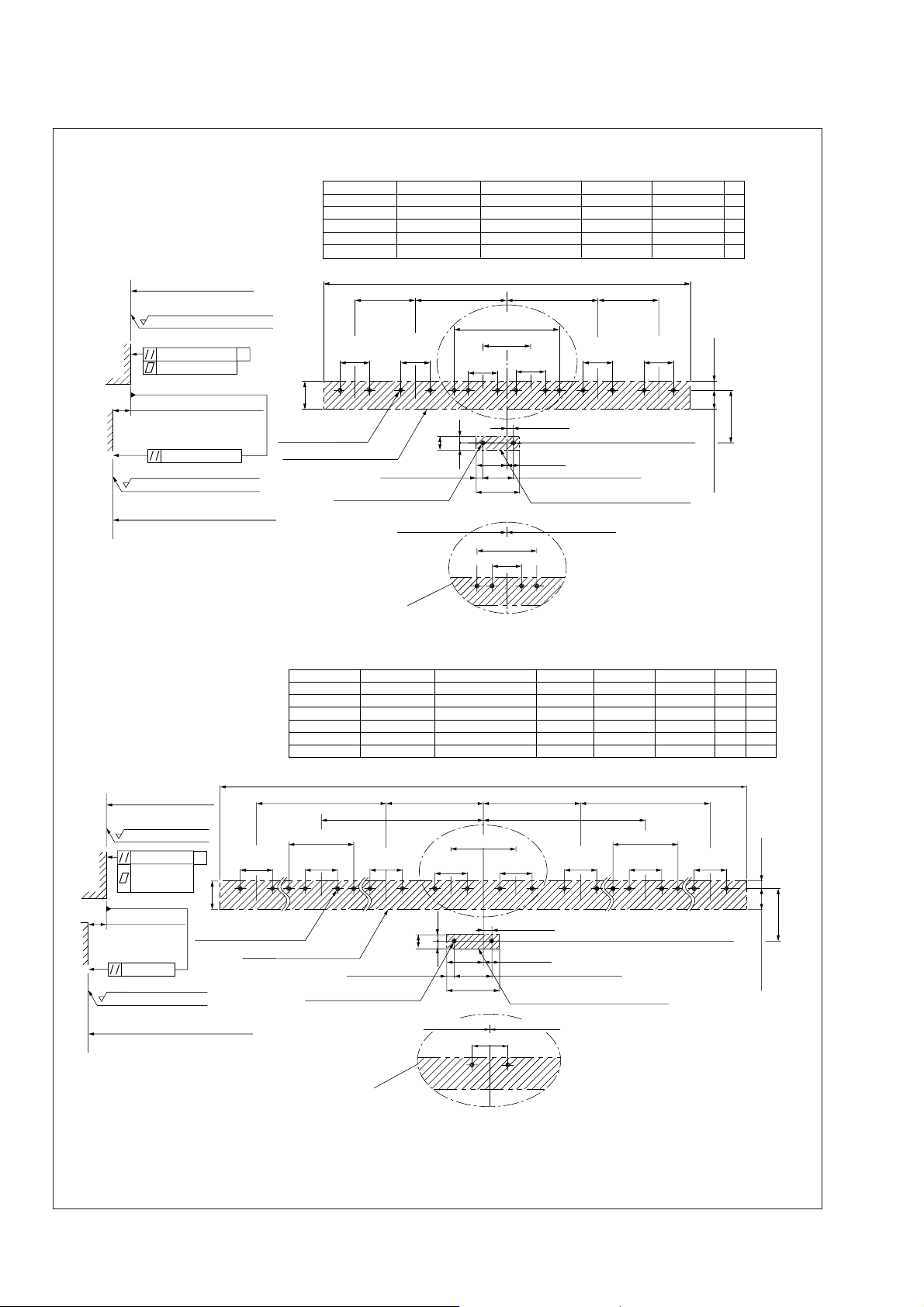
Soda lime glass models
Scale mounting surface
Rmax = 6.3S (250 µinch)
(Note 1)
0.01 (0.00039")
M
0.01 (0.00039")
16.4 ±0.2 (0.646" ±0.008")
0.02 (0.00079")
Rmax = 12.5S (500 µinch)
Detector head mounting surface
For BL57-016RE∗B, 036RE∗B
Model
BL57-006RE∗B
BL57-016RE∗B
BL57-026RE∗B
BL57-036RE∗B
BL57-046RE∗B
25 ±0.2
(0.984" ±0.008")
22 (0.866")
P-M4 depth: 6 (0.236")
Scale mounting surface
2-M4 depth: 10 (0.394")
Measuring length
60 (2.362")
160 (6.299")
260 (10.236")
360 (14.173")
460 (18.110")
25 ±0.2
(0.984" ±0.008")
(10.5)
(5.5) (0.217")
96 (3.780") or more
196 (7.717") or more
296 (11.654") or more
396 (15.591") or more
496 (19.528") or more
L1
88 ±0.3 (3.465" ±0.012")
40 ±0.2 (1.575" ±0.008")
25 ±0.2
(0.984" ±0.008")
5
(0.197")
(0.413")
5.5
(0.217")
28
(1.102")
38
(1.496")
50 ±0.3 (1.969" ±0.012")
25 ±0.2 (0.984" ±0.008")
L1
L2 ±1 (0.039")L2 ±1 (0.039")
L2
–
75 (2.953")
120 (4.724")
75 (2.953")
120 (4.724")
±
L3
25 ±0.2
25 ±0.2
(0.984" ±0.008")
(0.984" ±0.008")
4.5 (0.177")
10 (0.394")
27 ±0.2 (1.063" ±0.008")
Detector head mounting surface
L2 ±1 (0.039")L2 ±1 (0.039")
75 (2.953")
75 (2.953")
1 (0.039") L3 ±1 (0.039")
25 ±0.2
(0.984" ±0.008")
L3
P
–
6
–
8
–
10
12
14
(5)
(0.197")
0.2
0.008")
±
±
44.2
0.008")
±
(1.740"
16 ±0.2
(0.630"
Unit: mm (inch)
Scale mounting surface
Rmax = 6.3S (250 µinch)
0.1 (0.0039")
M
0.02 (0.00079")/
50 ±0.3 (1.969" ±0.012") 50 ±0.3 (1.969" ±0.012")
25 ±0.2
(0.984" ±0.008")
200 (7.874")
(Note 2)
16.4 ±0.2
(0.646" ±0.008")
22 (0.866")
P-M4 depth: 6 (0.236")
Scale mounting surface
0.02 (0.00079")
Rmax = 12.5S (500 µinch)
Detector head mounting surface
For BL57-066RE∗B, 096RE∗B, 106RE∗B
Model
BL57-056RE∗B
BL57-066RE∗B
BL57-076RE∗B
BL57-086RE∗B
BL57-096RE∗B
BL57-106RE∗B
Measuring length
560 (22.047")
660 (25.984")
760 (29.921")
860 (33.858")
960 (37.795")
1060 (41.732")
L1
596 (23.465") or more
696 (27.402") or more
796 (31.339") or more
896 (35.276") or more
996 (39.213") or more
1096 (43.150") or more
L2
100 (3.937")
75 (2.953")
100 (3.937")
100 (3.937")
75 (2.953")
75 (2.953")
L3
175 (6.890")
225 (8.858")
250 (9.843")
250 (9.843")
300 (11.811")
300 (11.811")
75 (2.953")
75 (2.953")
75 (2.953")
75 (2.953")
75 (2.953")
75 (2.953")
L1
NA × L4 ±1 (0.039") NA × L4 ±1 (0.039")
L2 ±1 (0.039") L2 ±1 (0.039")
L3 ±1 (0.039")L3 ±1 (0.039")
25 ±0.2
(0.984" ±0.008")
25 0.2
(0.984" ±0.008")
(5.5) (0.217")
2-M4 depth: 10 (0.394")
50 (1.969")
25 ±0.2
(0.984" ±0.008")
5
(0.197")
5.5
(0.217")
28
(1.102")
38
(1.496")
(10.5) (0.413")
25 ±0.2
(0.984" ±0.008")
25 ±0.2
(0.984" ±0.008")
4.5 (0.177")
10 (0.394")
27 ±0.2 (1.063" ±0.008")
Detector head mounting surface
25 ±0.2
(0.984" ±0.008")
L2 ±1 (0.039")L2 ±1 (0.039")
25 ±0.2 (0.984" ±0.008")
NA
L4
(0.984" ±0.008")
2
3
3
4
5
6
25 ±0.2
Unit: mm (inch)
16
18
20
24
26
30
16 ±0.2
P
(6)
(0.236")
44.2 ±0.2
(0.630" ±0.008")
(1.740" ±0.008")
3-4 (E)
Note 1: “M” refers to the machine guide.
Note 2: The flatness of the scale mounting surface must be within 0.02 over the range of 7 (width) × 200 (length) mm.
Fig. 3-4
BL57-RE
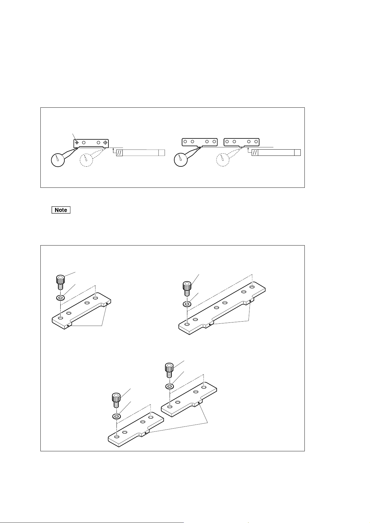
3-3. Scale Mounting
1 Check that there is no dust or other foreign substances on the mounting surface, and mount the reference
plate parallel to the machine guide as shown in the figure. (Fastening torque: 1.4 N · m)
The reference hole is located on the left, as shown in the figure. Adjust at the right side while observing
the parallelism with the lever type dial gauge.
BL57-003RE to 046RE BL57-056RE to 106RE
+
Reference ø4 0
0.05
0.01 (0.00039")
M
Fig. 3-5
0.1 (0.0039")
Note: “M” refers to the machine guide.
M
The scale is pressed against the reference plate for parallelism when mounting. The reference plate is
vital to accurate scale mounting. Be sure to always use the supplied screw and mount it exactly as
described in the specifications.
BL57-003RE, 011RE, 016RE, BL57-006RE, 026RE, 031RE, 046RE
021RE, 036RE, 041RE
M4 × 8
Plain washer (nominal 4)
Reference abutment
surface
M4 × 8
Plain washer
(nominal 4)
Reference abutment
surface
BL57-RE
BL57-056RE, 066RE, 076RE, 086RE, 096RE, 106RE
M4 × 8
Plain washer (nominal 4)
M4
×
8
Plain washer
(nominal 4)
Reference abutment
surface
Fig. 3-6
(E) 3-5
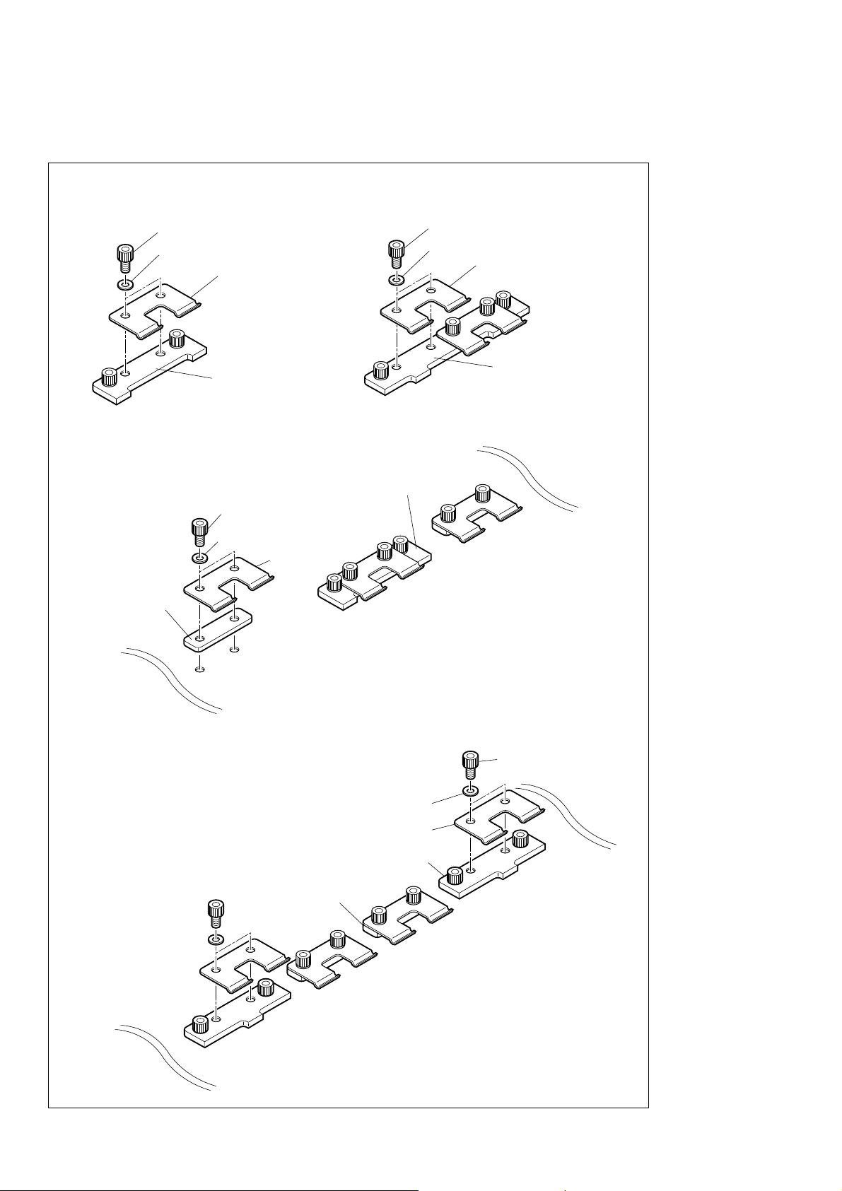
2 Attach the scale clamps loosely (1 or 2 full turns looser than the semi-tightened position) by using the
mounting screws, as shown in the figure.
BL57-003RE BL57-006RE, 026RE, 031RE, 046RE
M4 × 8
Plain washer (nominal 4)
Reference plate
Spacer
Scale clamp
BL57-011RE, 016RE, 021RE, 036RE, 041RE
Reference plate
× 8
M4
Plain washer (nominal 4)
Scale clamp
M4 × 8
Plain washer (nominal 4)
Scale clamp
Reference plate
3-6 (E)
BL57-056RE, 066RE, 076RE, 086RE, 096RE, 106RE
Plain washer (nominal 4)
Scale clamp
Reference plate
Spacer
Fig. 3-7
M4
×
8
BL57-RE
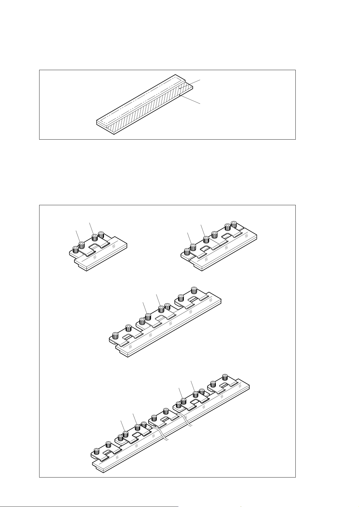
3 Check the mounting surface and the datum surface of the scale for dust and dirt. If the surfaces are dirty,
wipe them clean with gauze moistened with alcohol.
Mounting surface
Datum surface
Fig. 3-8
4 Insert the scale between the scale clamp and the mounting surface while pressing the datum surface of
the scale (see Fig. 3-6) lightly against the reference abutment surface (Note). Gradually and alternately
tighten screws A and B of the scale clamp indicated in the figure. (Use only the left-side scale clamp for
clamps with two screws, and use the center scale clamp for clamps with three screws.) (Final fastening
torque: 1.4 N · m)
BL57-003RE BL57-006RE, 026RE, 031RE, 046RE
B
A
B
A
BL57-011RE, 016RE, 021RE, 036RE, 041RE
B
A
BL57-056RE, 066RE, 076RE, 086RE, 096RE, 106RE
B
A
B
A
BL57-RE
Fig. 3-9
(E) 3-7

When pressing the scale against the datum surface, lightly press two points on the edge of the scale surface
opposite the datum surface with your fingers with a force of 9.8 N or less as shown in Fig. 3-10 on the left.
If the middle part of the scale is pressed with a force of 4.9 N or more as shown in Fig. 3-10 on the right, or
if the scale is installed with deformation, the specified accuracy cannot be achieved. (This also applies to the
following procedures. If it appears that the scale has been bent by force, loosen the scale clamp and mount it
again properly.)
BL57-003RE to 046RE
CORRECT WRONG
BL57-056RE to 106RE
CORRECT WRONG
Fig. 3-10
5 Leave the scale in the condition of Fig. 3-9 for one hour or more until the scale temperature stabilizes.
6 Secure the remaining scale clamps by gradually and alternately tightening screws A and B. (Use only
the right-side scale clamp for clamps with two screws, and use the right-side and the left-side scale
clamps for clamps with three screws.) (Final fastening torque: 1.4 N · m)
BL57-006RE, 026RE, 031RE, 046RE BL57-011RE, 016RE, 021RE, 036RE, 041RE,
B
A
056RE, 066RE, 076RE, 086RE, 096RE, 106RE
B
A
B
A
Fig. 3-11
3-8 (E)
BL57-RE
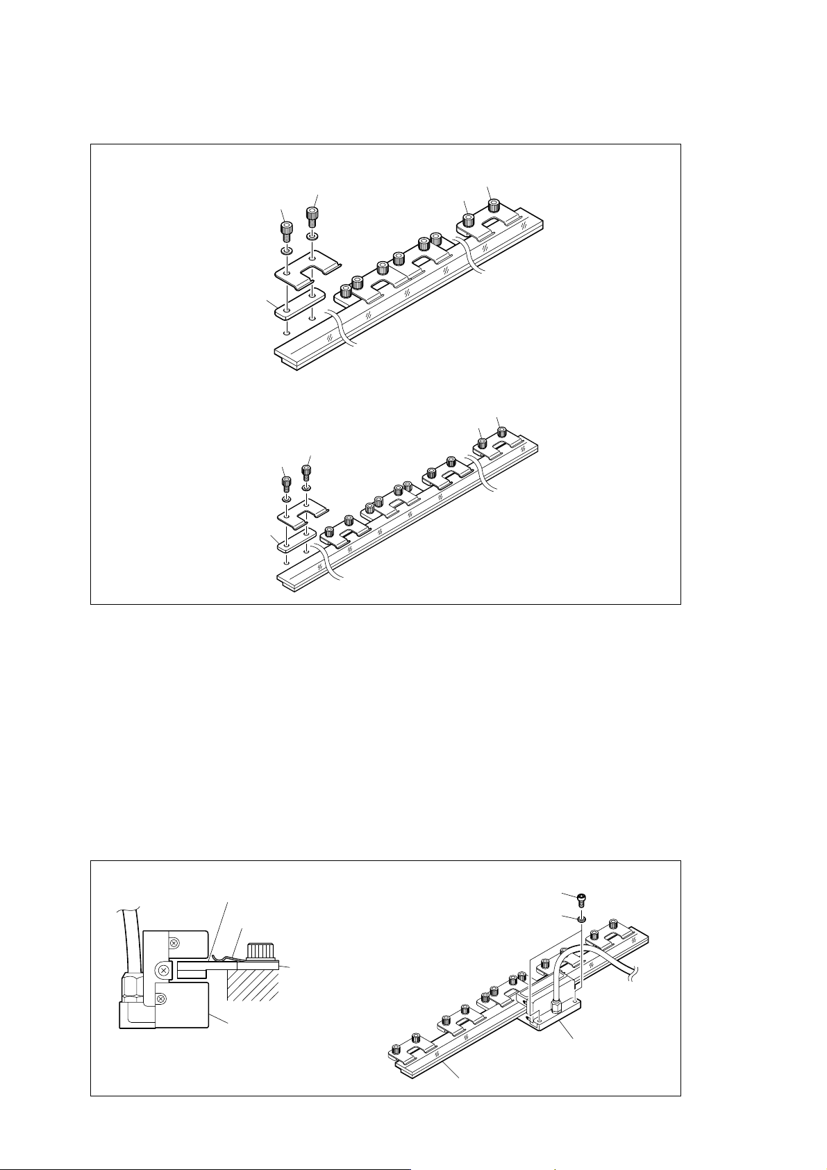
7 Fasten scale clamps on both ends of the scale with the same torque. (Final fastening torque: 1.4 N · m)
BL57-026RE, 031RE, 046RE
B
A
Spacer
BL57-016RE, 036RE, 041RE, 056RE, 066RE, 076RE, 086RE, 096RE, 106RE
B
A
B
A
B
A
Spacer
Fig. 3-12
8 Check the surface of the scale for oil and dust. If the surface is dirty, wipe it clean with gauze moistened
with alcohol. Be sure to wipe off oil and dust on the surface thoroughly.
3-4. Detector Head Mounting
1 Move the machine table and adjust the mounting position of the detector head to roughly the center of
the scale.
2 Use the supplied mounting screws to semi-tighten the detector head.
Detector head mounting screw
(M4
×
Scale
Scale clamp
12 hex. socket-head cap screw)
Plain washer (nominal 4)
BL57-RE
Reference
plate
Detector head
Detector head
Scale
Fig. 3-13
(E) 3-9
3-5. Signal Adjustment
3-5-1. Signal Adjustment Preparations
Check that the interface unit is turned off.
Refer to section 4-1 for removing and attaching the cover of the interface unit.
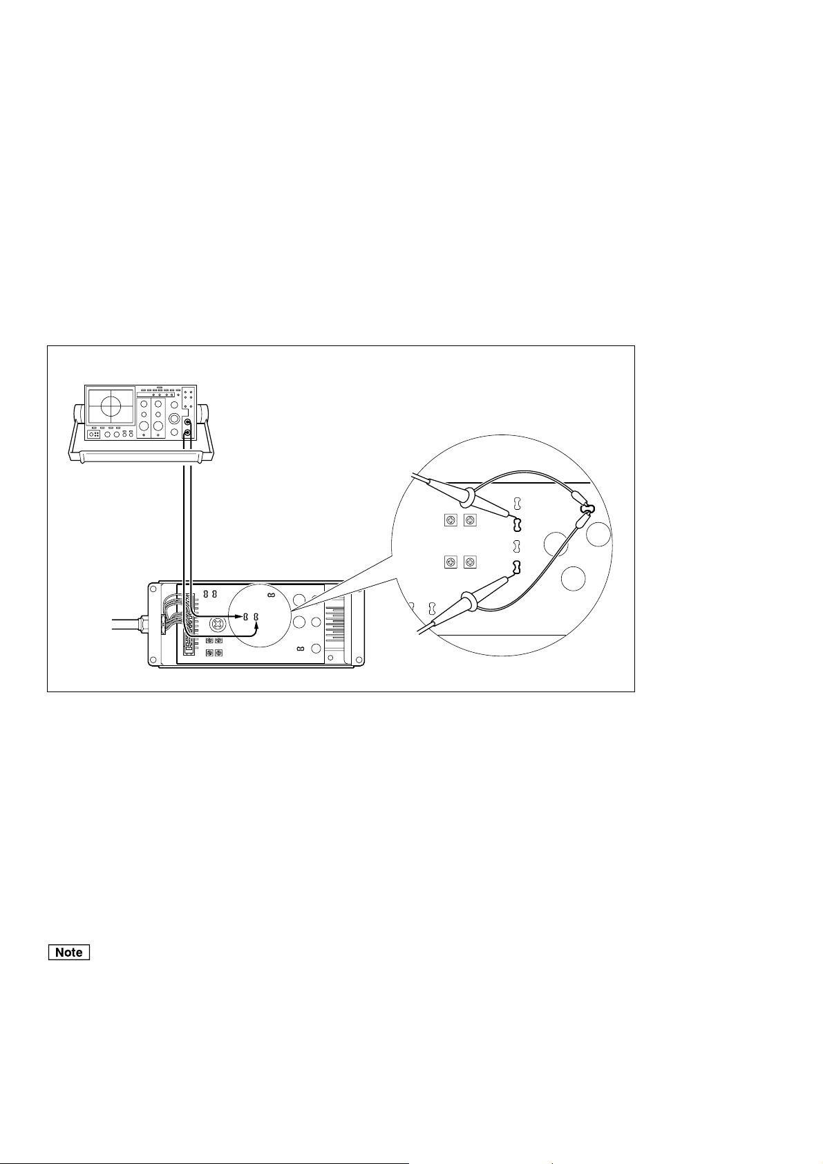
1
1 Connect the CH1 probe of the oscilloscope to the check pins
1 Output format F, G or H : TP3 (SIN) and TP8 (GND)
∗
2 Connect the CH2 probe of the oscilloscope to the check pins
2 Output format F, G or H : TP2 (COS) and TP8 (GND)
∗
∗
of the interface unit.
2
∗
of the interface unit.
Oscilloscope
CH1CH2
Probe
TP9
TP10
(LD)
(
)
APC
TP7
(
)
AGND
TP5
(
)
COS
TP1
(
)
SIN
TP8
(
DGND
Interface unit
3 Set the TIME/DIV switch to the X-Y mode.
)
Fig. 3-14
Signal adjustment
section-detailed view
Output format F, G, H
CH1
TP3
TP2
TP901
CH2
TP6
TP8
TP5
4 Set the deviation sensitivity (VOLTS/DIV) of CH1 and CH2 to 0.5 V/DIV.
5 Set the input coupling switches of CH1 and CH2 of the oscilloscope to GND, and adjust the position of
the oscilloscope so that the signal appears at the bottom left of the screen.
6 Set the input coupling switches of CH1 and CH2 of the oscilloscope to DC.
7 Turn the interface unit’s power on.
Be sure that the interface unit is turned off before attaching or removing the probe of the oscilloscope.
3-10 (E)
BL57-RE
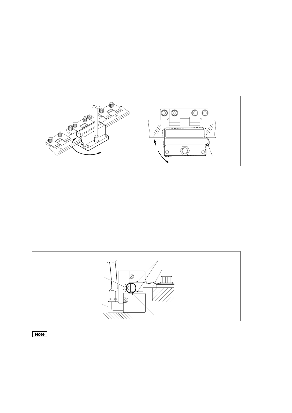
3-5-2. Azimuth Adjustment
The direction shown in the figure below is referred to as the azimuth direction. A stable output signal within
the range of the specified values can be obtained by adjusting the detector head direction.
<Specified values>
A/B signal output type ...... Output format F : Amplitude 0.7 Vp-p to 1.3 Vp-p
Output format G : Amplitude 0.8 Vp-p to 1.2 Vp-p
Analog output type ........... Output format H : Amplitude 0.6 Vp-p to 1.1 Vp-p
Azimuth direction
Azimuth direction
Fig. 3-15
Stopper
1 Loosen the detector head mounting screws, and then bring the stopper directly against the scale bottom
surface.
2 Rotate the detector head about the stopper in the azimuth direction as shown in Fig. 3-15 to find the
location where the Lissajous’ figure has the maximum amplitude.
3 Alternately tighten the two detector head mounting screws little by little at the detector head position
with the maximum amplitude of the Lissajous’ figure. (Fastening torque: 1.4 N · m)
4 Check that there is no interference between the scale and detector head.
Check for interference
Scale
Stopper
Detector head
Bring directly against
Fig. 3-16
Do not move the machine device with the stopper attached to detector head because this may result in
breakage of the detector head or the scale.
BL57-RE
(E) 3-11
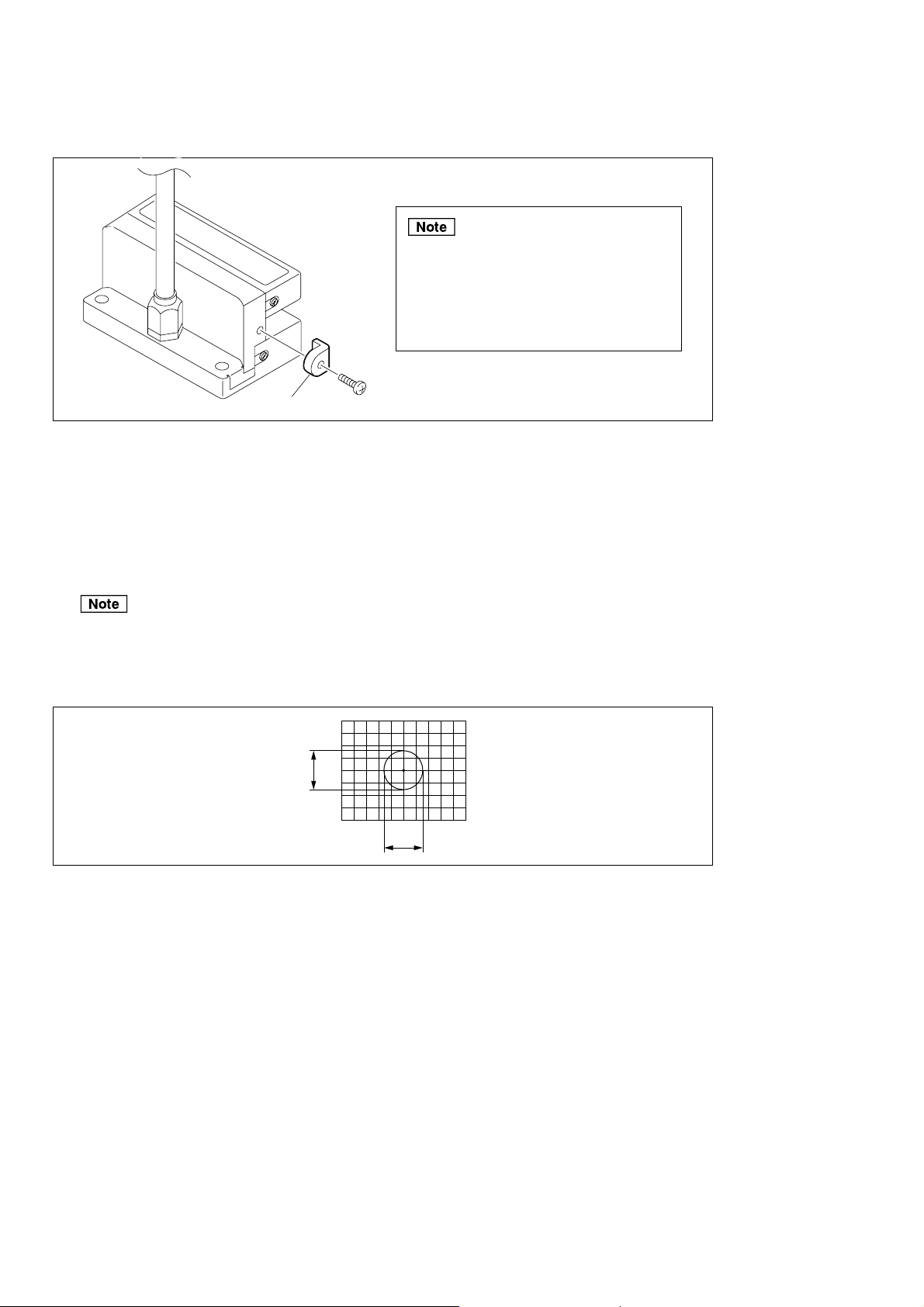
5 Remove the stopper from the detector head.
Do not move the machine device with
the stopper attached to detector
head because this may result in
breakage of the detector head or the
scale.
Stopper
Fig. 3-17
6 Move the scale, and make sure that the amplitudes A and B (see Fig. 3-18) of the Lissajous’ figure are
within the range of the specified values over the entire length.
<Specified values>
A/B signal output type ..... Output format F : Amplitude 0.7 Vp-p to 1.3 Vp-p
Output format G: Amplitude 0.8 Vp-p to 1.2 Vp-p
Analog output type........... Output format H: Amplitude 0.6 Vp-p to 1.1 Vp-p
The center of the Lissajous’ figure is 2.5 V.
If the output of 1 Vp-p cannot be obtained even through repeated adjustment, recheck the mounting
surface accuracy of the scale and detector head (refer to pages 3-3 to 3-4), and check again that there is
no dirt on the scale’s surface.
Lissajous
A
B
Fig. 3-18
3-12 (E)
BL57-RE
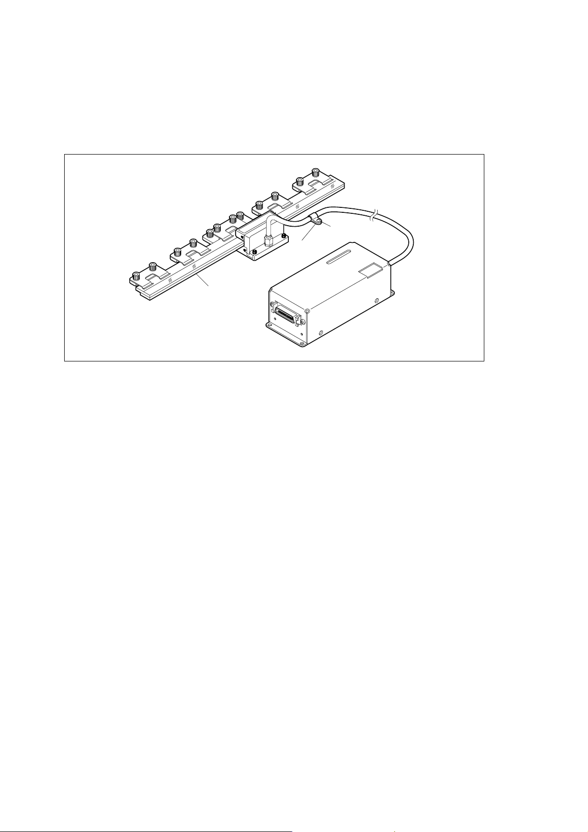
3-6. Completion of Mounting and Adjustment
• Secure the cable with the supplied cable clamp and pan-head screw (M4 × 8).
• Before using the scale to perform measurements, allow the scale to set for about three hours after mount-
ing so that the secured parts can stabilize and the ambient temperature around the scale can stabilize.
Pan-head screw
(M4
×
Cable clamp
Scale
8)
Fig. 3-19
BL57-RE
(E) 3-13

3-14 (E)
BL57-RE
4. Interface Unit
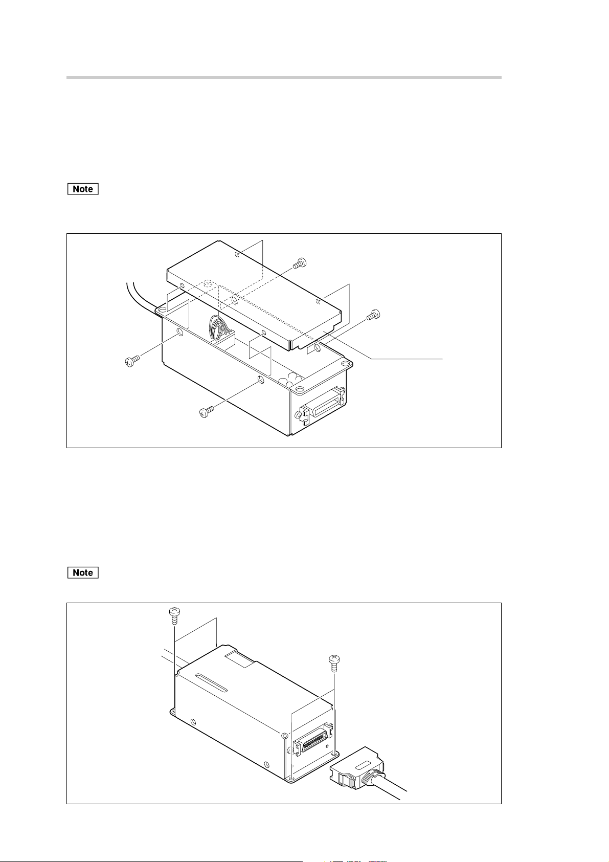
4-1. Removing and Attaching the Interface Unit Cover
To set or check the functions, remove the four screws, and then take off the interface unit cover.
When attaching the interface unit cover, place the cover so that the protruding surface is on the connector
side, and then retighten the removed screws in their original positions.
Tightening torque ......... 0.3 N · m
• Be careful not to lose the screws when you remove them.
• When attaching the interface unit cover, be sure that the protruding surface is on the connector side.
Protruding surface
Fig. 4-1
4-2. Installing the Interface Unit
Use the supplied screws to secure and attach the interface unit.
Firmly screw in the output connector.
Screw/Tightening torque ... M2.6 × 5: 4 pcs. / 0.8 N · m
Do not insert or remove the output connector while power is supplied to the interface unit.
BL57-RE
Fig. 4-2
(E) 4-1
5V
Magnescale Co
., Ltd.
CT COCO
ES WIWI
TH
21
CFR
J
BLE
OF
E.
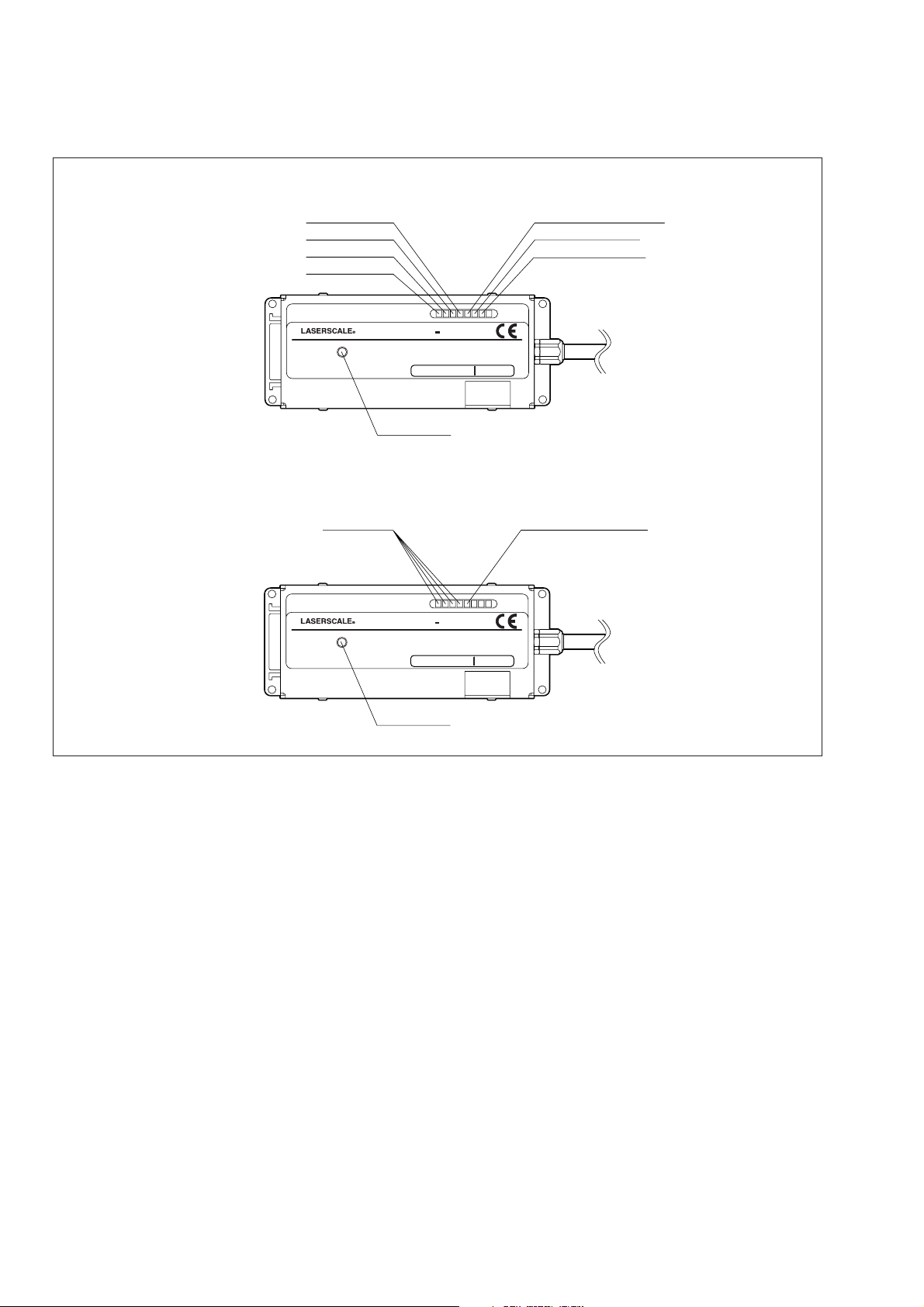
4-3. Names of LEDs
5V
Magnescale Co
., Ltd.
CT COCO
ES WIWI
TH
21
CFR
J
BLE
OF
E.
A/B signal output type: Output format F and G
Analog output type: Output format H
POS. lamp 1
POS. lamp 2
POS. lamp 3
POS. lamp 4
Magnescale Co
., Ltd.
POS. lamp
Magnescale Co
., Ltd.
CERTITIF I CAT IOION
MP L I ES
PR ODU CT
AP P L I CACABLE
J
POPOWER R SUSUPP LY : DC
Powe r lamp
CERTITIF I CAT ION
PR ODU CT
MP L I ES
AP P L I CACABLE
J
POPOWER R SUSUPP LY : DC
BL57
TH
AT T DA T E E OF
+
5V
BL57
TH
AT T DA T E E OF
+
5V
DH HS S RULULES S 21
MA NU F AC T UR E.
DH HS S RULULES S 21
MA NU F AC T UR E.
CFR
CFR
SU B CH APTPTER
MADADE E IN N JAPAPAN
Reference point lamp
SU B CH APTPTER
MADADE E IN N JAPAPAN
Reference point lamp
Level alarm lamp
Speed alarm lamp
Power lamp
Fig. 4-3
4-2 (E)
BL57-RE
 Loading...