


LASER REFERENCE, Inc.
450 Salmar Avenue
Campbell, CA 95008
•
USA
PRO SHOT
Operations Guide
TM
L4 & L4
+
Toll Free (USA)
Telephone
Web
Email
+
1.800.238.0685
+
1.408.370.4929
Fax
+
1.408.866.0858
www.proshotlaser.com
sales@proshotlaser.com
Customer information
Laser Serial number _____________________________
Receiver S/N __________________________________
Date of purchase _______________________________
Version 3
Part No. 010-9060

Introduction
Thank you for purchasing a Pro ShotTM L4 or L4+ laser system. You now
have superior laser accuracy and productivity available for all your projects.
Pro ShotTM laser models L4 and L4+ are rugged, reliable, high quality
products, backed by the industry leading Guardian 36 month warranty.
Warranty details are printed in the back of this manual.
Please take the time to thoroughly read this manual. It contains vital
information on how to safely get the most from your investment in laser
technology.
Contents
Warranty
Guardian 36 month warranty coverage
The L4 and L4+ laser transmitters, and the R7 receiver, are warranted for
thirty-six (36) months from the date of new equipment purchase from an
authorized dealer. During the warranty period, Laser Reference, or its
authorized service center, will repair or replace, at Laser Reference's sole
discretion, laser transmitters or receivers, free of charge, (except for
transportation costs) if the products are found by Laser Reference, or its
authorized service center, to be defective in either materials or workmanship.
The
Guardian
mechanism and internal optics against damage from any cause. Maintaining
the calibration of the product is not the responsibility of Laser Reference or
its authorized service centers. If service is needed, the product(s) must be
sent FREIGHT PREPAID to the nearest authorized service center or to
Laser Reference.
36 month warranty also covers the internal leveling
17
Battery Installation ............................................................... 1
Controls and Displays
Controls and Displays
Safety • L4 and L4+
Initial Setup Guidelines ........................................................ 6
Level Setup • On Tripod ....................................................... 7
Vertical & Line Layout Setup ............................................... 8
Plumb and Layout Setups
Applications • L4 ................................................................ 10
Applications • L4+ ............................................................... 11
Accessories ....................................................................... 12
R7 Receiver ....................................................................... 13
Checking & Adjusting Calibration ...................................... 14
Maintenance and Troubleshooting .................................... 16
Guardian Warranty and Specifications ......................... 17
•
L4 .................................................. 2
•
L4+ ................................................. 3
.........
...................................................... 4
•
L4+ ........................................... 9
Specifications
L4 Range (with receiver) .......
L4+ Range (with receiver) .....
Rotational Coverage .............
Accuracy ...............................
Self-Leveling Range ..............
Vertical Capability .................
Power Supply ........................
Run Time on New Batteries ..
Automatic Shut-off ..............
Rechargeable Batteries .......
Environmental .......................
Rotation Speed .....................
Operating Temp. (ambient) ...
Storage Temperature ............
Safety - L4 .............................
Safety - L4+ ..........................
Height ....................................
Weight ...................................
750' rad., 1500' dia. (230m/460m)
1000' rad., 2000' dia. (305m/610m)
360 degrees
±10 arc seconds (1/16" per 100')
(1.6mm per 30m)
±10 arc minutes
Built-in vial, optional mount
(L4+ system includes mount)
Four C-Cell batteries
L4: 70 hours (alkaline)
L4+: 60 hours (alkaline)
If off-level for more than 3 min.
Available option
Dust and water resistant
L4: 600rpm / L4+: 0 to 450rpm
-0ºf to +122ºf (-18ºc to +50ºc)
-40ºf to +140ºf (-40ºc to +60ºc)
CDRH and IEC 825-1 Class II
CDRH and IEC 825-1 Class IIIa
9in (23cm)
4.1lbs (1.86kg)

Maintenance And Troubleshooting
Calibration • There is no set interval for calibrating the L4 or L4+, but
calibration should be checked from time to time in order to ensure that the
highest possible quality of work is being done. Calibration should always be
checked if the laser has been handled roughly or shipped.
Batteries • Occasionally remove the batteries and check the contacts for
corrosion. Alkaline batteries will last far longer than carbon batteries. If you
use rechargeable batteries, be careful to never charge alkaline or carbon
batteries. Also, do not charge Ni-Cd batteries too often. Ni-Cd batteries
should be charged after about 20 to 24 hours of operation. Never run the
laser from the charger unless there are rechargeable batteries installed.
Keep a spare set of batteries in the carrying case to avoid down time.
Laser output windows • Regularly check the output windows for dust and
dirt. Dust can be removed with a camera brush or clean compressed air.
Control panel and exterior • Clean the control panel and the other exterior
surfaces of the laser with a soft damp cloth.
Caution • Never store the laser in a carrying case that is wet inside.
Moisture can get inside the laser this way. Should this happen, remove the
battery cover and place the laser in a warm area until it is completely dry.
Troubleshooting
The laser will not operate, there is no obvious damage • If the low battery
indicator is on, or you suspect the batteries may be dead, replace the
batteries. Check the battery contacts to be sure that they are clean.
The receiver shows an on-grade at two different heights • Check the
jobsite for windows or mirrored surfaces that might be reflecting the laser and
causing the other reading. Check for others on the site using a rotary laser.
The laser was knocked over • Visually check the optics for damage.
Inspect the laser for any other physical damage. Use the receiver to check
that the laser is transmitting. Check the calibration and adjust as needed.
Check to see that the laser displays the "limit" light when the circular level
vial bubble moves approximately half way outside the circle.
The laser only works at short distances • Check the output windows for
heavy dust or moisture. Remove dust with a camera brush or blow off gently
with clean compressed air. Allow moisture to dry.
The receiver does not indicate "on grade" at long distance • Be sure you
are within 750ft (230m) from the laser. Check the windows that surround the
rotating mirror on the laser for dust or moisture. Remove dust with a camera
brush or blow off gently with clean compressed air. Allow moisture to dry.
16
Battery Installation
1
Battery charging jack
For connecting battery charger
when using rechargeable batteries.
(see pg. 12 for accessory info.)
!
Charge only
Ni-Cad batts.
Battery door release screw
Releases with 1/4 turn counter-
clockwise.
Battery installation
Install batteries as shown here.
For reference, a diagram is
molded onto the battery holder.

Controls and Displays L4
1
2
3
1
Power button • When pressed, the rotating mirror will begin to spin and
the laser beam will be projected if the circular level is centered. If the
laser is not level enough to operate, the limit indicator will flash.
2
Circular level vial • The circular level indicates when the laser is rough
leveled enough to allow the automatic compensator to work.
3
Leveling knobs • Use to center the bubble in the circular level vial. The
leveling knobs are also used during vertical alignment (see page 13)
4
Leveling Limit indicator • If the L4 is powered on, but not level enough
to automatically compensate, the limit indicator will flash, the rotating
mirror will not spin, and no laser beam will be projected.
5
Low battery indicator • Will flash when the batteries need to be replaced
and the beam will turn off. A spare set of batteries can be carried in the
laser case to prevent downtime.
6
Vertical vial • Used to plumb the plane of laser light when the laser is in
the vertical mode (see page 7). The laser is completely manual in the
vertical mode and will not shut-off if the vertical vial is not centered.
note: The leveling screws are
at 90º to the leveling pivot
5
point, which is directly below
the circular vial. As you face
the control panel and look
down at the circular vial, the
4
leveling screw on your right
controls bubble movement
from left to right. The leveling
screw at the back, below the
6
battery door, controls bubble
movement from front to back.
Turning the leveling screw on
your right in a clockwise
motion will move the bubble to
the right and turning the back
leveling screw in a clockwise
motion will move the bubble to
the back. Turning each screw
counter-clockwise will have
the opposite effect.
2
Checking & Adjusting Calibration
15
7. Remove the upper black rubber plug below the control panel. Using a
3/32" hex driver, adjust the X-axis calibration. Turning the screw clockwise
will raise the beam in the -X-axis (see opposite page). One full turn of the
screw will make approximately a 3/4"(19mm) change at 100'(30m) turn the
screw a little at a time until the beam matches the true level mark. Do not
move the laser or platform during this adjustment.
8. Check the X-axis adjustment: rotate the laser back to the first direction
and re-center the bubble. Check that the reading is within the needed
tolerance of the true level mark.
9. Rotate the laser 90 degrees to aim the +Y-axis (control panel) at the
target. Re-center the bubble. Check the reading at the target. If the reading
is on, or within tolerance of the true level mark, calibration is complete. If not,
continue on.
10. Remove the lower black rubber plug. Using a 3/32" hex driver, adjust
the Y-axis calibration. Turning the screw clockwise will raise the beam in the
+Y-axis (see opposite page). One full turn of the screw will make
approximately a 3/4"(19mm) change at 100'(30m) turn the screw a little at
a time until the beam matches the true level mark. Do not move the laser or
platform during this adjustment.
11. Rotate the laser 180 degrees. The -Y-axis is now aimed at the target.
Re-center the bubble.
12. Compare the elevation of this axis to the true level mark. If the
difference between this reading and true level is within your working
tolerance, calibration is complete. If not, use the procedure in step 10 to
balance this axis with the +Y-axis.
Calibration is now complete.
Checking & Adjusting Calibration
14
Calibration is your responsibility, check it often.
Although the L4 and L4+ are exceptionally rugged lasers, it is well worth the
effort to check calibration before you first use them and then at regular
intervals to insure that you are doing the highest quality work possible.
Always check calibration if the laser has been handled roughly.
Calibration procedure.
1. Attach the laser to a stable tripod or stand approximately 100 feet (30m)
from a wall or other stable vertical surface. We will call the vertical surface
the target. Make the tripod head level enough to allow the laser to be aimed
in different directions with minimal re-leveling of the circular level vial.
2. Turn the entire laser so that either direction of the x-axis (picture below) is
aimed at the target. Note: the axes are the same for both models.
3. Center the circular level vial
and turn the laser on.
-Y axis
-X axis
+X axis
+Y axis
4. Take the receiver to the
target and find the height of the
laser beam. All receivers have
a "deadband" at their center.
The most precise way to take a
reading is to make two marks.
Slowly move the receiver from
above until you get an on-grade
display and make a mark. Next,
slowly move the receiver from
below until you get an on-grade
X axis
display and make a second
mark. Half way between these
two marks is the exact reading.
Y axis
5. Return to the laser and rotate
it 180 degrees. The opposite Xaxis direction should now be
aimed at the target. Re-center
the bubble in the circular level.
Find and mark the laser beam
height at the target.
6. The difference between the two marks (if any) is double the difference
between how the laser is calibrated and true level for the X-axis. Half way
between these two marks is true level. Make a long mark at true level. If the
difference between either outer mark and true level is within your working
tolerance, go on to step 9. If not, continue with the next step.
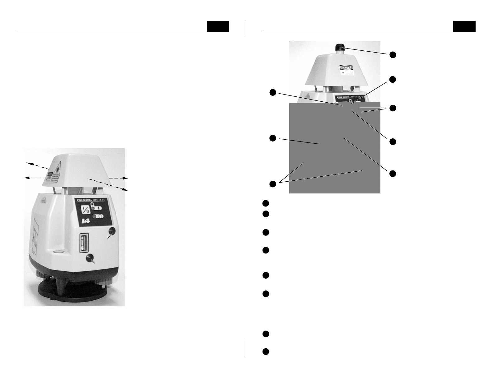
Controls and Displays
1
2
3
1
Power button • Press the power button to turn the laser on or off.
2
Circular level vial • Indicates when the laser is close enough to level to
•
L4
+
7
note: The leveling screws are
at 90º to the leveling pivot
point, which is directly below
5
the circular vial. As you face
the control panel and look
down at the circular vial, the
leveling screw on your right
controls bubble movement
6
from left to right. The leveling
screw at the back, below the
battery door, controls bubble
movement from front to back.
Turning the leveling screw on
4
your right in a clockwise
motion will move the bubble to
the right and turning the back
leveling screw in a clockwise
motion will move the bubble to
the back. Turning each screw
8
counter-clockwise will have
the opposite effect.
allow the automatic compensator to function.
3
Leveling screws • Used to center the bubble in the circular level vial.
The knobs are also used during vertical alignment (see page 13)
4
Leveling limit indicator • If the L4+ is powered on, but not level enough
to automatically compensate, the limit indicator will flash, the rotating
mirror will not spin, and no laser beam will be projected.
5
Power and low battery indicator • Displays a green light when the laser
is powered on. The light will flash red if the batteries need to be replaced.
6
Speed control buttons • The (+) and (-) buttons adjust rotation speed. A
single push will make the speed slightly faster or slower. If you push and
hold the (+) button, the rotation will adjust to full speed. You will know
that full speed has been reached when the green power indicator flashes.
If you push and hold the (-) button, the rotation will slow and then stop.
7
Beam aiming knob • When the rotation is stopped, push and turn this
knob to aim the beam. Push the knob in and hold it in while turning.
8
Vertical vial • The vertical vial is used to plumb the plane of laser light
when the laser is in the vertical mode (see page 13).
3

Safety • L4 and L4+
4
R7 Receiver
13
Precautions to follow when using any laser.
• Don't stare into the laser beam or view it directly with optical instruments.
• Don't disassemble the laser or attempt to service it.
• Don't use the laser until you have read the instruction manual and you are
familiar with how to operate the laser properly.
U.S. OSHA requirements for operating visible lasers.
• Only qualified, trained employees may install, adjust and operate the laser.
• Laser operators must carry proof of qualification.
• The area of a job site where a laser is being used must be posted with a
laser warning placard.
• The laser should be set up above eye level and never intentionally aimed at
anyone.
• Turn the laser off when it is not being used, such as during lunch hour, at
the end of the day, or during other long breaks in the work.
Caution and certification label locations - L4
CDRH / IEC
warnings
CAUTION
LASER LIGHT
DO NOT STARE
INTO BEAM
CLASS II LASER PRODUCT
Aperture
warning
Serial / CDRH / EC
Made in U.S.A. by: Laser Reference, Inc.
450 Salmar Ave. • Campbell, CA 95008
This product complies with FDA
standards 21 CFR subchapter J
Serial No.
Note: The L4 transmitter is a class II laser under the 1993 IEC 825-1 laser
safety standard and the revised edition of the European Norm EN60825.
The L4 laser conforms to applicable EC directives regarding RFI and EMI.
The L4 complies with FDA performance standards 21 CFR sub-chapter J.
LASER LIGHT
DO NOT STARE INTO BEAM
CLASS 2 LASER PRODUCT
Light is emitted
from this aperture
AVOID EXPOSURE
compliance
X 000000
Laser
The R7 can be attached to a grade
rod, or used without the rod clamp
to make reference marks on walls,
Rear height display
floors, or other surfaces. The R7
senses the laser beam and uses a
five channel front LCD to display
5 channel front
height display
height information. LEDs are used
to display the same information on
the back. When the R7 is exactly
at the beam height, the on grade
indication is displayed. If the R7 is
high or low, either the above grade
or the below grade indication will
be displayed showing the direction
to move the R7 in order to get on
R7
PRO SHOT
PRO SHOT
grade. The R7 has three control
buttons, a power on/off button, a
tone high/low/off button and a
button to select on-grade accuracy.
The R7 automatically turns off if no laser beam strikes are received for twelve
minutes. The tone comes on high (loudest) when the R7 is powered on.
Pressing the tone button once changes to low tone, twice turns the tone off.
When the tone is off, there will still be a single tone the first time the R7
senses a laser signal. The R7 is powered by a 9 volt battery that lasts
approximately 60 hours. When the battery is used up, the low battery
indicator will be displayed. To access the battery, locate the battery door on
the back of the housing and slide the door toward the bottom of the receiver.
The door can stay attached to the housing when it is fully open. Remove the
battery from the compartment (you may need to tap the R7 on your palm to
free the battery). Replace the battery following the diagram molded on the
battery door.
R7 Specifications:
Reception Height ....................
Reception Angle .....................
On-Grade Accuracy ................
Power Supply .........................
Battery Life ..............................
Automatic Shut Off .................
Environmental ........................
Rotation Compatibility ............
Rod Mount Clamping Range ..
2 inches (50mm)
120 degrees
Standard: ±1/16in (±1.6mm) nominal
Coarse: ±1/8in (± 3.2mm) nominal
Ultra-fine: ±1/64in (±.4mm) nominal
9 volt battery
60 hours continuous (alkaline)
After 12 min. (no laser strikes)
Sealed against dust and water
250 to 850 R.P.M.
5/8in to 2-1/2in (16mm-65mm)

Accessories
W1 Wall and Vertical mount
The W1 is part of the basic package for the L4+
and is an available option for the L4 to allow
vertical setups for layout work or plumbing walls
or posts in a plane.
The P1 allows quick and easy setups
for getting the L4+ over a point to transfer
points from floor to ceiling.
P1 Plumb Plate
B40 Rechargeable Battery Kit
The B40 kit provides four industrial grade
Nickel-Cadmium batteries and a 110v
charger that plugs into the charging jack
MT1 Magnetic Target
Two Mt1 targets are included in the basic
package for the L4+. MT1 targets are available
as replacements or to allow additional workers
to use the laser on larger jobs.
at the rear of the laser.
Charge only
Ni-Cad batts.
!
12
Safety • L4 and L4+
Caution and certification label locations - L4+
Warning, Class IIIa label for lasers
sold in the U.S. and Canada
5
Warning, Class IIIa labels for lasers
sold where IEC standards apply
LASER LIGHT
DO NOT STARE INTO BEAM
OR VIEW DIRECTLY WITH
OPTICAL INSTRUMENTS
CLASS 3A LASER PRODUCT
Aperture
warning
Laser
Light is emitted
from this aperture
AVOID EXPOSURE
Serial / CDRH / EC
compliance
Made in U.S.A. by: Laser Reference, Inc.
450 Salmar Ave. • Campbell, CA 95008
This product complies with FDA
standards 21 CFR subchapter J
Serial No.
X 000000
Note: The L4+ transmitter is a class IIIa laser under the 1993 IEC 825-1
laser safety standard and revised edition of the European Norm EN60825.
The L4+ laser conforms to applicable EC directives regarding RFI and EMI.
The L4+ complies with FDA performance standards 21 CFR sub-chapter J.
A laser warning placard is included with lasers shipped to the U.S. and Canada.
It may be attached to the carrying case - with the case visible and placed near
where the laser is being used - for meeting job site posting requirements.
CAUTION
LASER LIGHT
DO NOT STARE INTO BEAM
CLASS 2 LASER PRODUCT
LASER LIGHT
DO NOT STARE
INTO BEAM
CLASS II LASER PRODUCT
L4
L4+

Initial Setup Guidelines
6
Applications • L4
+
11
Calibration is your responsibility, check it often.
Although the L4 and L4+ are exceptionally rugged lasers, it is well worth the
effort to check calibration before you first use them and then at regular
intervals to insure that you are doing the highest quality work possible.
Always check calibration if the laser has been handled roughly. See
"checking / adjusting calibration" on page 20.
Check your setup.
Outdoors: Check your setup from time to time, using engineered
benchmarks on the jobsite to assure that your work is correct and matches
the design of the job. Realize that even engineered benchmarks may not be
perfect and enough verification must be done to be confident you are
properly set up. If there are not suitable benchmarks on the site, you should
set your own by driving stakes and recording their elevations, or by marking
the laser beam height on stable objects such as telephone poles, concrete
walls, etc. The benchmarks should be 900 apart for greatest accuracy.
Having benchmarks to check is of great value for jobs where setups need to
match day after day.
Indoors: Make reference marks, preferably 900 apart, along the beam travel
once you have set the laser up either horizontally or vertically. Check your
setup from time to time using the marks as a guide.
Work as close to the laser as possible.
You can work up to 750 feet (230 meters) from the L4 and L4+ with the R7
receiver, or with the MC-1 machine control receiver. As with all instruments,
the further away you work, the more any error can add up. Set the laser in a
safe place, as close to your work as possible.
Ceilings
Walls
Layout
The W1 wall and vertical mount, provided in the
system, allow the L4+ to be attached to T-bar
wall angle. A "0" height mark on the W1 sets
the beam at finished ceiling elevation for
installing wall angle. A -2" (-50mm) mark sets
the beam at the center of the system magnetic
targets for installing the grid.
The W1 mount, makes vertical setups for steel
wall alignment easy. Setting the W1 mount to
the "vert" mark aligns the rotating beam with
the edge of the mount to align top, bottom
channels. The mount can then be moved to a
2" (50mm) offset to allow the magnetic targets
to be used for checking stud placement.
With its 90º fixed spot, the L4+ eliminates the
need to use 3-4-5 calculations or other difficult
methods to align right-angle intersections. One
person can easily accomplish layout tasks,
even on large commercial sites.
Maintain your equipment.
Keeping tripod and mount hardware tight, and being sure grade rods are in
good condition, can prevent errors and performance problems.
Plumb
Transferring points from floor to ceiling or
maintaining alignment on high-rise structures
can be accomplished very accurately with the
L4+. The low cost accessory P1 plumb plate is
used to precisely locate the L4+ over a point for
this type of work.

Applications • L4
The L4 Provides a precise reference
for level alignment needs such as:
• Setting concrete forms
• Setting grout pads
• Checking grades
• Checking base material
• Digging footers and basements
• 4ft (or 1m) marks
Vertical Alignment
Along with the ability to project a level
reference plane, the L4 has a built-in
manual vial for aligning the plane of light
vertically using the W1 accessory mount.
This plumb plane can be used for:
• Aligning bolts and wall plates
• Layout work
• Plumbing walls and panels
• Transferring lines from floor to ceiling
• Aligning and plumbing posts and tall
forms
10
Level Alignment
Level Setup • On Tripod
7
Be sure to read the "initial setup guidelines" section (pg 6).
Using the two leveling knobs, center the bubble in the circular level vial (see
procedure on pages 2 or 3 if you have any difficulty). Facing the laser control
panel and looking down at the circular level vial, when you turn either leveling
screw clockwise, the bubble will move toward that leveling screw. Once the
bubble is centered, start the laser by pressing the power (0/l) button .
If extreme distance is required, the L4 or L4+ can be set-up in the middle of a
site, covering a total diameter of 1500 feet (460 meters) with the R7 receiver
or the MC-1 receiver.
Periodically check your setup against existing benchmarks or set and check
your own benchmarks.

Vertical and Layout Setup
•
L4
8
Attach the laser to the W1 wall/vertical mount, adjusting the flat edge of the
base, where the laser mounts, to the red L4 "vert" mark. Remove the
receiver from the rod clamp, turn it on and set it on a far point. With the
beam window facing the laser, use the beam center notch for alignment.
Return to the laser/mount assembly and set the edge of the mount that is just
below the laser's beam exit slot over a near point. Note that the surface the
W1 is resting on should be reasonably level. Rough align the assembly by
holding the edge on the near point and sliding the base of the assembly until
the receiver's audio tone begins. Use the Y-axis leveling screw (now at the
bottom of the laser) to rough center the vertical vial (visible through the small
window now at the top of the laser).
The X-axis leveling knob (now near the top of the laser) is used as a fine
mechanical line control to center the beam plane on the receiver. The
receiver's audio tone will become constant when the beam is centered on the
receiver. Make a final adjustment of the vertical axis vial after the alignment
is done and re-align to the receiver if necessary. Note that the laser is
completely manual when in the
vertical mode and you will have to
check the bubble from time to
time to insure accuracy. Draw a
line along the edge of the W1 to
allow you to verify that the mount
has not been moved.
The W1 can also be tripod
mounted for vertical setups.
• Check the vertical vial and
your benchmarks regularly to
be sure your work will be
accurate. The L4 and L4+ have
been engineered to perform
vertical alignment up to two
stories high.
Shown on optional W1 mount.
See Page 12 for accessories.
Plumb and Layout Setups
Plumb beam
•
L4
+
9
To transfer a point from floor to ceiling,
the accessory P1 plumb plate is used.
• Set the P1 over the point
• Set the L4+ on the P1
• Level the L4+ circular vial
• Switch the laser on
• A plumb beam is projected from the
top of the L4+, directly over the point.
Hole to center
P1 over point
Point to transfer
P1 plumb plate
Fixed
beam
When the L4+ is in
vertical mode as
shown above, it is
capable of projecting a
vertical plane of rotating
90º
Rotating
beam
laser light and a
simultaneous fixed beam
at 90º to the rotating plane.
Please refer to page 13 "vertical & line layout setup" for complete instructions
on aligning the vertical plane of light. The 90º beam provides a convenient
way to define right angle intersections for interior layout.
 Loading...