


LT-2D3D
User Manual v2.12
Edited: August 19, 2016

2 | P a g e
Table of Contents
1.0 Jobsite Setup .................................................................................................................................... 6
1.1 LT-2D3D Setup ............................................................................................................................. 6
1.2 LT-2D3D Jobsite Setup ................................................................................................................ 6
2.0 Using The Laser Templator Software ............................................................................................. 7
2.1 Help ............................................................................................................................................. 7
2.1.1 Check for Updates ..................................................................................................................................7
2.1.2 Import/Export Settings...........................................................................................................................7
2.1.3 Manual ...................................................................................................................................................7
2.1.4 About......................................................................................................................................................7
2.1.5 View Changes .........................................................................................................................................7
2.1.6 Tips .........................................................................................................................................................8
2.1.7 Setup Device ..........................................................................................................................................8
2.2 New ............................................................................................................................................. 8
2.3 Open ............................................................................................................................................ 8
2.3.1 Hard Drive ..............................................................................................................................................8
2.3.2 Drop-In ...................................................................................................................................................8
2.3.3 Auto Save ...............................................................................................................................................8
2.3.4 Other (Advanced) ...................................................................................................................................9
2.3.5 Drive Info ................................................................................................................................................9
2.4 Import/Export ............................................................................................................................. 9
2.4.1 Estimate .................................................................................................................................................9
2.4.2 PDF (Print) ............................................................................................................................................ 10
2.4.3 Shop Sheet ........................................................................................................................................... 11
2.4.4 Email ..................................................................................................................................................... 11
2.4.5 Upload to Job Tracker .......................................................................................................................... 11
2.4.6 Import Job Tracker Data ....................................................................................................................... 12
2.5 Save ........................................................................................................................................... 12
2.6 Save As ...................................................................................................................................... 12
2.6.1 Hard Drive ............................................................................................................................................ 12
2.6.2 Drop-In ................................................................................................................................................. 12
2.6.3 Other (Advanced) ................................................................................................................................. 13
2.6.4 Drive Info .............................................................................................................................................. 13
2.7 Exit ............................................................................................................................................. 13
2.8 Connect To Laser ....................................................................................................................... 13
2.9 Options ...................................................................................................................................... 14
2.9.1 General Settings ................................................................................................................................... 14
Save Settings ...................................................................................................................................................... 14
Print Settings ...................................................................................................................................................... 15
Drawing Display Settings .................................................................................................................................... 15
Job Details Settings ............................................................................................................................................. 15
Miscellaneous Settings ................................ ................................................................ ................................ ....... 16
Job Tracker Settings............................................................................................................................................ 16
2.9.2 Estimate Settings .................................................................................................................................. 16
2.9.3 Quick Actions ....................................................................................................................................... 17
2.9.4 E-Mail Settings ..................................................................................................................................... 17
2.9.5 Advanced.............................................................................................................................................. 19
2.9.6 Shortcuts .............................................................................................................................................. 19

3 | P a g e
2.10 Job Info / Pages ......................................................................................................................... 19
2.10.1 General ............................................................................................................................................ 19
2.10.2 Address ............................................................................................................................................ 19
2.10.3 Dates ............................................................................................................................................... 19
2.10.4 Additional Items .............................................................................................................................. 20
2.10.5 Pages ............................................................................................................................................... 20
2.10.6 Notes ............................................................................................................................................... 21
2.10.7 Agreement ....................................................................................................................................... 21
2.11 Move Circle................................................................................................................................ 21
2.12 Split Line .................................................................................................................................... 21
2.13 Flip / Scale ................................................................................................................................. 22
2.14 Add Photo .................................................................................................................................. 22
2.15 Erase Segment ........................................................................................................................... 22
2.16 Erase All On Page ...................................................................................................................... 23
2.17 Split Object On Point................................................................................................................. 23
2.18 Units .......................................................................................................................................... 23
2.18 Rotate Drawing ......................................................................................................................... 24
2.19 Mirror ........................................................................................................................................ 24
2.20 Object Info ................................................................................................................................. 24
2.21 Circle Diameter.......................................................................................................................... 24
2.22 Display Measured Points .......................................................................................................... 24
2.23 Display Contiguous Breaks ....................................................................................................... 25
2.24 Display Polylines ....................................................................................................................... 25
2.25 Display Color Names ................................................................................................................. 26
2.26 Display Area Legend .................................................................................................................. 26
2.27 Re-Position Laser ....................................................................................................................... 27
2.28 Set Plane .................................................................................................................................... 27
2.29 Offset ......................................................................................................................................... 28
2.29.1 Offset Scribed Wall .......................................................................................................................... 28
2.29.2 Offset Polygon ................................................................................................ ................................ . 28
2.30 Define (0,0) ................................................................................................................................ 28
2.31 Slab Layout ................................................................................................................................ 28
2.32 Backsplash ................................................................................................................................. 30
2.33 Angle .......................................................................................................................................... 30
2.34 Radius ........................................................................................................................................ 30
2.35 Dimensions ................................................................................................................................ 30
2.36 Maximum Dimensions .............................................................................................................. 30
2.37 Text ............................................................................................................................................ 30
2.38 Center Line ................................................................................................................................ 30

4 | P a g e
2.39 Line ............................................................................................................................................ 31
2.40 Arc .............................................................................................................................................. 31
2.41 Circle .......................................................................................................................................... 31
2.42 Circle .......................................................................................................................................... 32
2.43 Ellipse ........................................................................................................................................ 32
2.44 Cross .......................................................................................................................................... 32
2.45 Custom Box ............................................................................................................................... 32
2.46 Menu Bar Functions .................................................................................................................. 33
2.46.1 Laser On ........................................................................................................................................... 33
2.46.2 Start New Line ................................................................................................................................. 33
2.46.3 Laser Off .......................................................................................................................................... 33
2.46.4 Zoom ............................................................................................................................................... 33
2.46.5 Best Fit ............................................................................................................................................. 33
2.47 Laser Mode ................................................................................................................................ 34
2.48 Erase .......................................................................................................................................... 34
2.49 Distance ..................................................................................................................................... 34
2.50 Auto Fillet .................................................................................................................................. 34
2.51 Fillet ........................................................................................................................................... 34
2.52 Offset ......................................................................................................................................... 35
2.53 Rotate ........................................................................................................................................ 35
2.54 Extend ........................................................................................................................................ 36
2.55 Draw Segment ........................................................................................................................... 36
2.56 Dimensions ................................................................................................................................ 36
2.57 Color .......................................................................................................................................... 36
2.58 Drop-In ...................................................................................................................................... 37
2.59 Quick Action .............................................................................................................................. 37
2.60 Undo .......................................................................................................................................... 37
2.61 Redo ................................................................................................................................ 37
3.0 Bluetooth Pairing ................................................................................................................. 38
3.1 Pair Laser to the Tablet PC (Pre-February, 2016) ............................................................... 38
3.2 Setting Comports (Purchased Pre-February, 2016) ............................................................ 39
3.3 Pair Laser to the Tablet PC (Purchased Post-February, 2016) ............................................. 39
3.4 Setting Comports (Purchased Post-February, 2016) ........................................................... 40
4.0 Methods of Use .................................................................................................................... 41
4.1 Tripod Setup / Mounting .................................................................................................. 41
4.2 Jobsite Placement ............................................................................................................ 41
4.3 Targets ....................................................................................................................................... 41
4.3.1 Pin Targets............................................................................................................................................ 41

5 | P a g e
4.3.2 “T” Targets ........................................................................................................................................... 41
4.3.3 Clamp Targets ...................................................................................................................................... 41
4.3.4 Black Shields ......................................................................................................................................... 41
4.4 Causes of Bad Measurements .................................................................................................. 41
4.4.1 Reflection ............................................................................................................................................. 41
4.4.2 Drastic Angles ....................................................................................................................................... 42
4.4.3 Dirty Lens ............................................................................................................................................. 42
4.5 Micro Adjust .............................................................................................................................. 42
4.5.1 Mounting on Tripod ............................................................................................................................. 42
4.5.2 Usage .................................................................................................................................................... 42
4.5.3 Adjusting Tension ................................................................................................................................. 42
4.6 Micro Adjust .............................................................................................................................. 42
5.0 Power Information ........................................................................................................................ 43
5.1 Battery Life ...................................................................................................................... 43
5.2 Battery Indication LEDs (Pre-February, 2016) .................................................................... 43
5.3 Battery Indication LEDs (Purchased Post-February, 2016) .................................................. 43
5.4 Charging at Home and in a Car.......................................................................................... 43
5.5 Normal Power Off Procedure ........................................................................................... 44
6.0 General Information ...................................................................................................................... 45
6.1 Warranty Information............................................................................................................... 45
6.2 Laser Safety Guidelines ............................................................................................................. 45
6.3 Using the Computer with Other Programs .............................................................................. 46
6.4 Cleaning / General Care and Storage ....................................................................................... 46
6.5 LT-2D3D Laser Templator Specifications .................................................................................. 46
6.6 Training Videos ......................................................................................................................... 47
7.0 Technical Information ................................................................................................................... 48
7.1 Accuracy and Distance Specifications ...................................................................................... 48
7.2 Storage and Operating Temperatures ...................................................................................... 48
7.3 Laser Specifications ................................................................................................................... 48
8.0 Contact Information ...................................................................................................................... 49
9.0 Registration ................................................................................................................................... 50

6 | P a g e
1.0 JOBSITE SETUP
1.1 LT-2D3D Setup (Purchased Pre-February, 2016)
1. When you walk into the job site, turn on the tablet and set up the tripod while the tablet is booting.
2. Place the laser on the tripod and make sure it is in plane with the countertops.
3. Plug in the USB cable into the tablet after Windows has fully started.
4. Once the USB cable is connected, press the power button on the side of the laser.
5. After the laser shows a green LED on the side next to Power, start the program by double clicking on it on the
desktop. You should wait at least 5 seconds between turning on the laser and opening the program to allow the
laser enough time to turn on and start the Bluetooth Service.
6. You will be prompted with a window that tells you to make sure the laser is locked before proceeding.
7. You will see in the top bar “LT Connected”
a. If the top bar shows “LT Disconnected”
i. Exit the program.
ii. Unplug the USB cable and plug it back in.
iii. Make sure the laser is on indicated by the green light on the side of the laser next to Power.
iv. Start the program by double clicking on program on the desktop.
v. If it is still not connected, check for any pending Windows Updates that need to be installed.
8. After connected, press Laser On or Start New Line and you can begin templating.
1.2 LT-2D3D Jobsite Setup (Purchased Post-February, 2016, marked R4.1 on the bottom
label)
1. When you walk into the job site, turn on the tablet and set up the tripod while the tablet is booting.
2. Place the laser on the tripod.
3. Plug in the USB cable into the tablet after Windows has fully started.
4. Once the USB cable is connected, press the power button on the side of the laser.
5. After the laser shows a green LED on the side below Power, start the program by double clicking on it on the
desktop. You should wait at least 5 seconds between turning on the laser and opening the program to allow the
laser enough time to turn on and start the Bluetooth Service.
6. You will be prompted with a window that tells you to make sure the laser is locked before proceeding.
7. You will see in the top bar “LT Connected”
a. If the top bar shows “LT Disconnected”
i. Exit the program.
ii. Unplug the USB cable and plug it back in.
iii. Make sure the laser is on indicated by the green light on the side of the laser below Power.
iv. Start the program by double clicking on program on the desktop.
v. If it is still not connected, check for any pending Windows Updates that need to be installed.
8. Set the plane you are going to measure by capture three points.
a. You will be prompted to set a plane before capturing any points with the laser. If you are not going to
template immediately, you can ignore the following steps and use other functions.
b. Points should be at least 12” apart and should not be in a straight line.
c. Clicking the “Show Example” button in the software will bring up an image showing where to position
the three points. The points only need to generally be in a left, right, back/top orientation to one
another
9. After connected, press Laser On or Start New Line and you can begin templating.

7 | P a g e
2.0 USING THE LASER TEMPLATOR SOFTWARE
File Menu
The File menu is where you will find the most basic actions that will be performed when starting a new job, saving a job,
opening previous jobs and adding information of a job.
2.1 Help
The Help menu is where you will find a comprehensive source of information on the Laser Templator software. Please
use this resource if you have any questions about the software. If your question is not answered here, contact us at our
main office. We are open Monday through Friday, 9:00 am through 5pm, Central Standard Time.
Laser Products Industries
1344 Enterprise Dr.
Romeoville, IL 60446
877-679-1300
www.LaserProductsUS.com
2.1.1 Check for Updates
Every time you open our software, if there is an active internet connection, it will check to see if there are updates
available for it. However, if none are found because you have a slower connection, you can also use this function
to check as well.
2.1.2 Import/Export Settings
We allow you to import and export your program settings so easily set up both your tablet and your office
computer (second seat) the same way.
To Export:
1. Click the browse button (…)
2. Type in a file name
3. Choose the location you want to save it to and press Save
4. Press Export
To Import:
1. Click the browse button (…)
2. Select the file you want to import
3. Click Open
4. Click Import
2.1.3 Manual
This is the Manual you are looking at right now. It has been compiled up to version 2.1.
2.1.4 About
Located in the About section, you will be presented with current information about the software version you are
currently running as well as copyright information on our software.
2.1.5 View Changes
This section of the Help menu simply lists what is changed from the previous version. New features, bug
fixes and other general information on new releases are all shown.
8 | P a g e
2.1.6 Tips
This section of the Help menu offers tips for the user of the laser. As tips are submitted by our
customers, they will be added to this menu. If you wish to submit a tip, please email
info@laserproductsus.com with the subject of Tip.
2.1.7 Setup Device
Setup Device allows you to choose what COM port both the Laser and Encoder are communicating to the
tablet PC on. This will not show up on non-Bluetooth versions of the laser and will be already set up
when your laser arrives. If we send you a loaner tablet PC while yours is being repaired, this will need to
be set up. See Section 4.0 Bluetooth Pairing.
2.2 New
Selecting New will give you a blank canvas to start a new job.
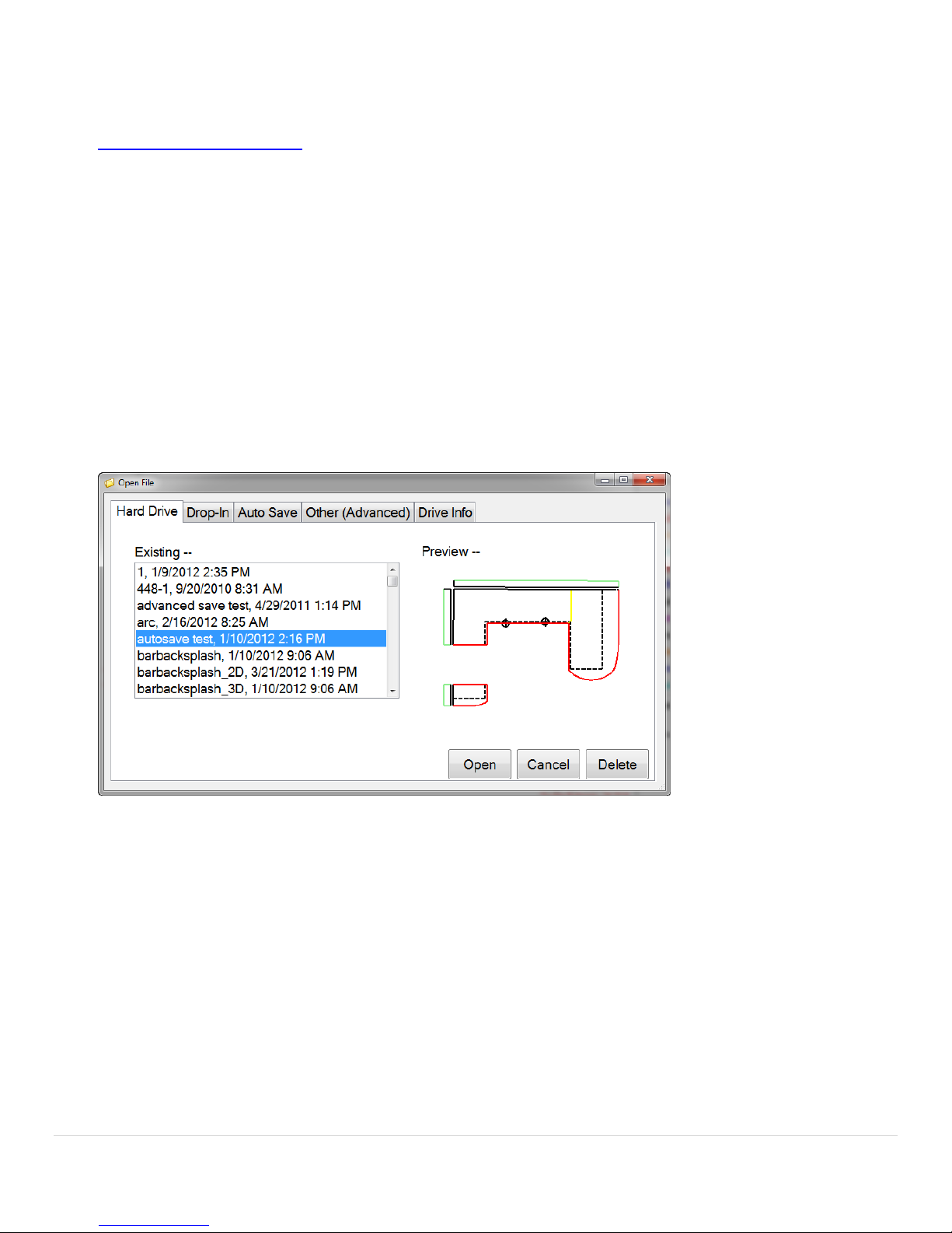
2.3 Open
In the Open section, you will be presented with 4 different options to opening files. You can open files from the Hard
Drive, Drop-Ins, Auto Save files and you can use an Advanced open menu.
2.3.1 Hard Drive
Open Opening files from the 3THard Drive3T will show you all of the templated jobs you have saved on the hard drive
of the tablet/computer. These templates are located in the 3TMy Documents3T folder of the tablet/computer.
2.3.2 Drop-In
If you create a 3TDrop-In3T like a special corner, bump out or a sink bowl and you want to save it for future use, this is
where it will be located. The templates that are located here are the ones you will see when you choose the 3TDrop-
In3T feature.
2.3.3 Auto Save
An 3TAuto Save3T occurs while the tablet is sitting idle and more frequently when being used. This is done as a backup
if you make a mistake and need to go back to a previous version of the template or you forget to save your job. If
you finish a job and forget to save the template, you can look in the 3TAuto Save3T area and open the most recent
one.
9 | P a g e
You should not rely on these files because if you close the program out before an auto save occurs, only the most
recent action made before the previous auto save will be saved and be available. Anything made after the last
auto save will not be recorded.
2.3.4 Other (Advanced)
The 3TOther (Advanced)3T option for opening jobs should be used if you do not save your templates in the 3TMy
Documents3T folder or on your SD memory card. By using this option, you can open up and job files that are located
anywhere on the tablet.
2.3.5 Drive Info
Drive Info simply shows you how much memory is currently being used and is available on your system.
2.4 Import/Export
We offer the ability to import and export data from our software in a multitude of formats.
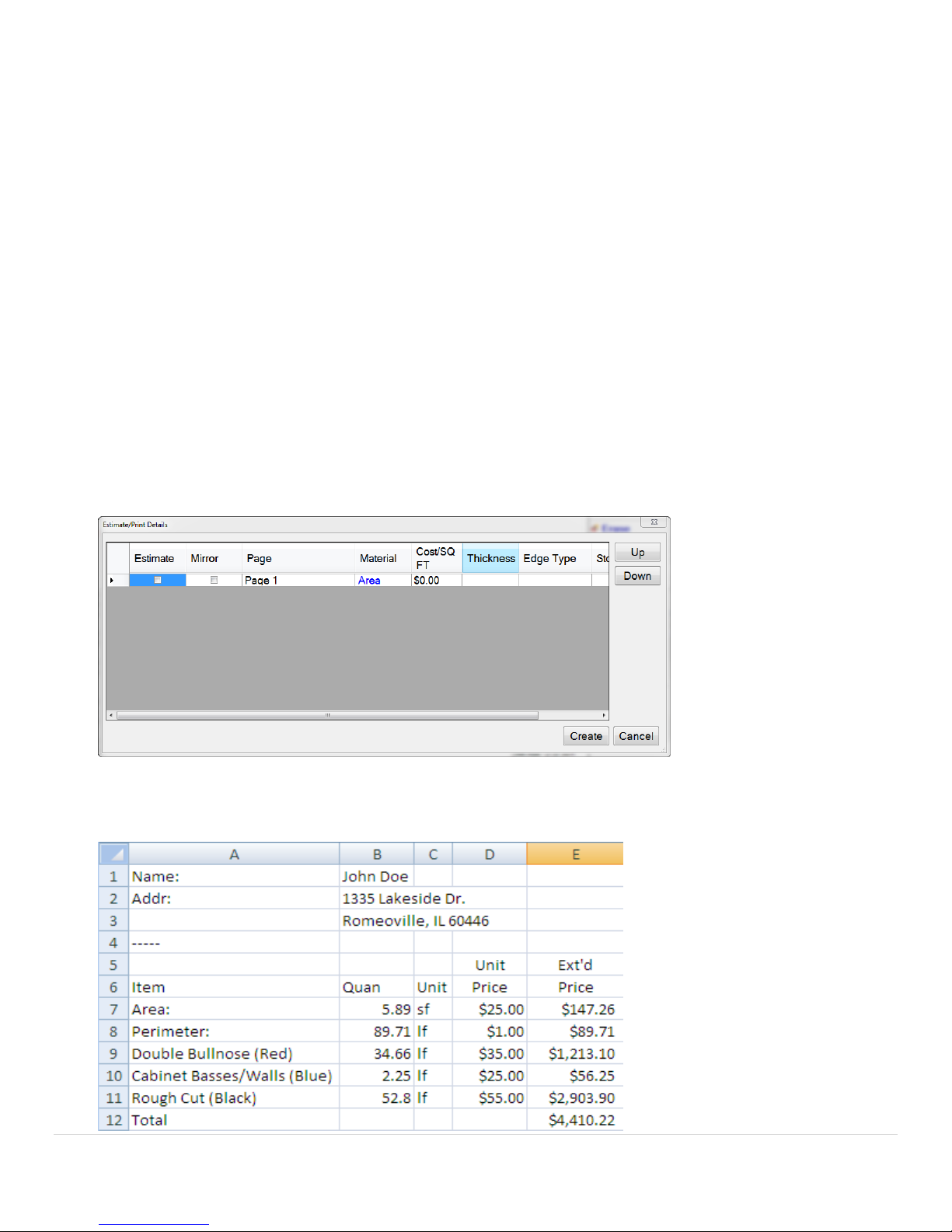
2.4.1 Estimate
Using the Estimate function will open up an Excel based spreadsheet showing you common estimate values like
sq. footage, perimeter, costs based on different edge treatments as well as a total cost of the job. These numbers
can be used for customer quotes or just for internal estimations of cost per job.
First you will see the Estimate/Print Details page where you can set up your Estimate. You can choose to print the
basic Estimate or you can add the Summary, Estimate and Pages.
10 | P a g e
A .csv estimate file will be saved to the job folder where the templated .dxf file is as well as the photographs of the
job if you choose to use them.
2.4.2 PDF (Print)
You will need to have a printer installed on the tablet or on your computer to print these out. If you do not have a
printer, you can save the .pdf file to later transfer it to a computer that has printing capabilities if you just want to
save the digital file for your records.
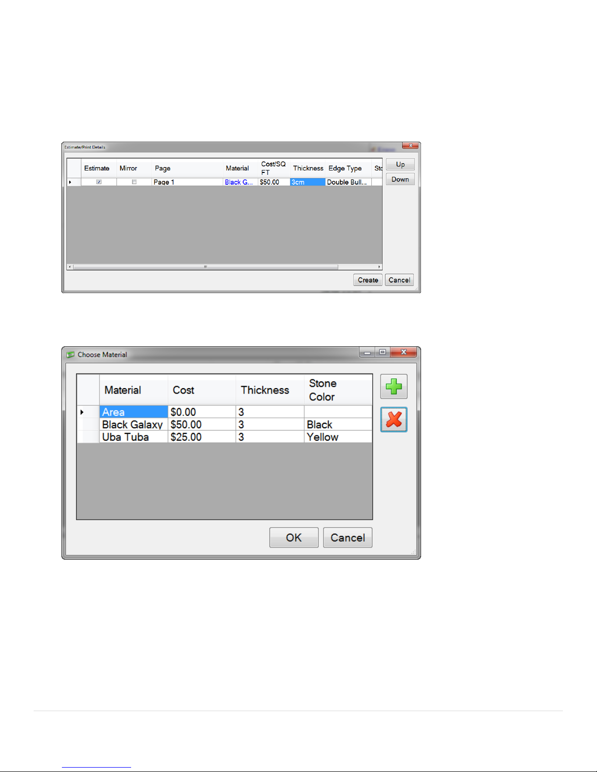
If you wish to store a database of material (type of stone) you have in inventory, click on Area. You will be
presented with a window that will allow you to add the material of your choice.
1. To add materials, click the green plus sign.
2. Click in the Material box and type in the name of the material.
3. Click in the Cost box and type in a cost of the material.
4. Add a Thickness and Color.
5. To remove a material, click on the material and click on the red x.
6. To choose your material click on the material name and click OK.
Use the check boxes on the bottom half of the screen and check the boxes if you want this to be included in your
print out. If you uncheck a box, it will not be included.
11 | P a g e
2.4.3 Shop Sheet
The shop sheet is a .pdf file that is created specifically for the fabrication facility in your business. Information on
this form is filled out in the Job Information Center and the individual Page information. One shop sheet is
automatically created for each page in your job.
2.4.4 Email
If you want to E-Mail your job files back to your fabrication shop, you will first need to set up your email settings.
To do so, follow the instructions in section 2.9.4 - E-Mail Settings.
To send an email, enter the address you want to send the job to, the Subject (usually the job name) and any
comments in the Message field. Check the boxes on the right to include whatever files you want. Sending pictures
and PDF’s will slow down the process of sending because of the file sizes. We suggest only sending the L55 and
DXF files when emailing. Photos can be included if needed. All the PDF files can be recreated at the office by
opening the job file and saving it again.
2.4.5 Upload to Job Tracker
In version 2 of the software, we have added Moraware’s Job Tracker integration. You can now import job
information from Job Tracker’s website as well as export/upload the job files created with the laser. To use this
functionality, you will need to first set up your account in our Options menu.
1. Click Edit / Options
2. Scroll to the bottom of the General Setting tab where you will see Job Tracker Settings
3. Enter the API URL (which is https://<xyz>.moraware.net/<xyz>/api.aspx where <xyz> is your own
company information)
4. Enter your User Name
5. Enter your Password
6. Press OK
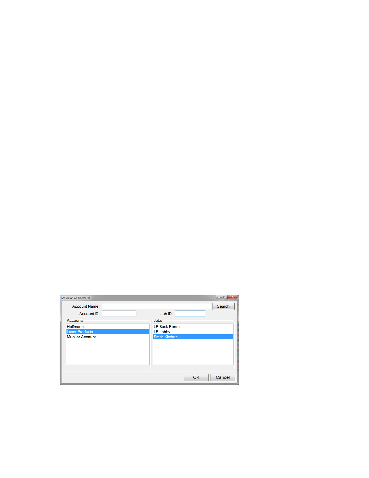
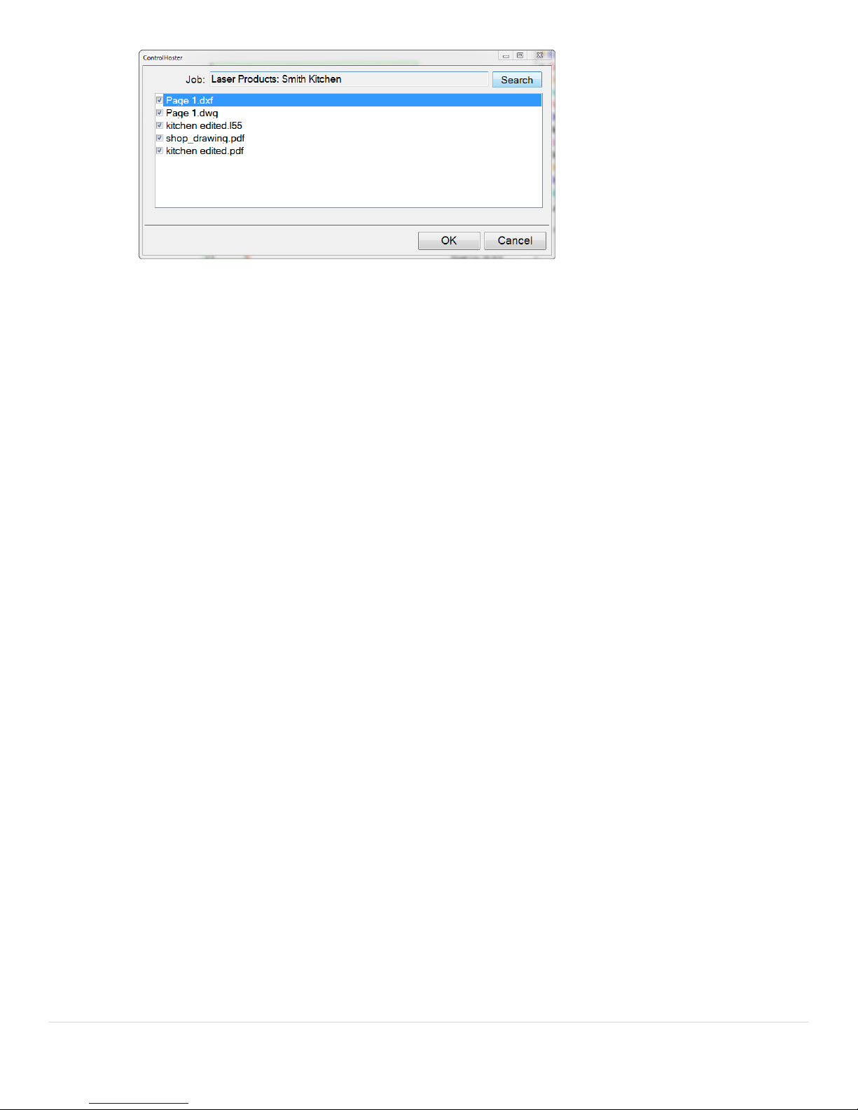
To upload data to Job Tracker
1. Have the job you want to upload open
2. Click File / Import/Export / Upload to Job Tracker
3. Click Search
4. Click on the Account and Job you want to upload the job files to
5. Check the boxes of the files you want to upload
12 | P a g e
6. Click Ok.
2.4.6 Import Job Tracker Data
Now that you have your Job Tracker account settings ready in the program, you can import the job information.
1. Click File / Import/Export / Import Job Tracker Data
2. Select the Account that the job is saved under
3. Select the Job that you want to import the data from
4. Click Ok.
The job’s data will now be visible in the Job Information area of the software.
2.5 Save
Choosing to Save your project should be done frequently. The current version of the job will be saved when you press
3TSave3T. If this is the first time the job is being saved, it will ask you to enter a name for it. Once a name is associated with
the file, choosing save will just overwrite the older version with the current one.
The program saves files with .l55 extensions. This is the file that contains all measurement information and recorded
date. From this file, .dxf, .dwg, .ord, .xml, .csv, .txt, and .pdf files can be recreated. The only files that are not recreated
from the .l55 file are the .jpg files (images).
The .l55 file will have all points flattened to a horizontal 2D plane (if the 'Template Wall' function was used, the points
will be flattened to a vertical 2D plane).
The 'INTERNAL 3D IMAGE.dxf' file located in the same job folder will have all the points saved in 3D space in a point
cluster that can be opened and edited in a separate CAD program.
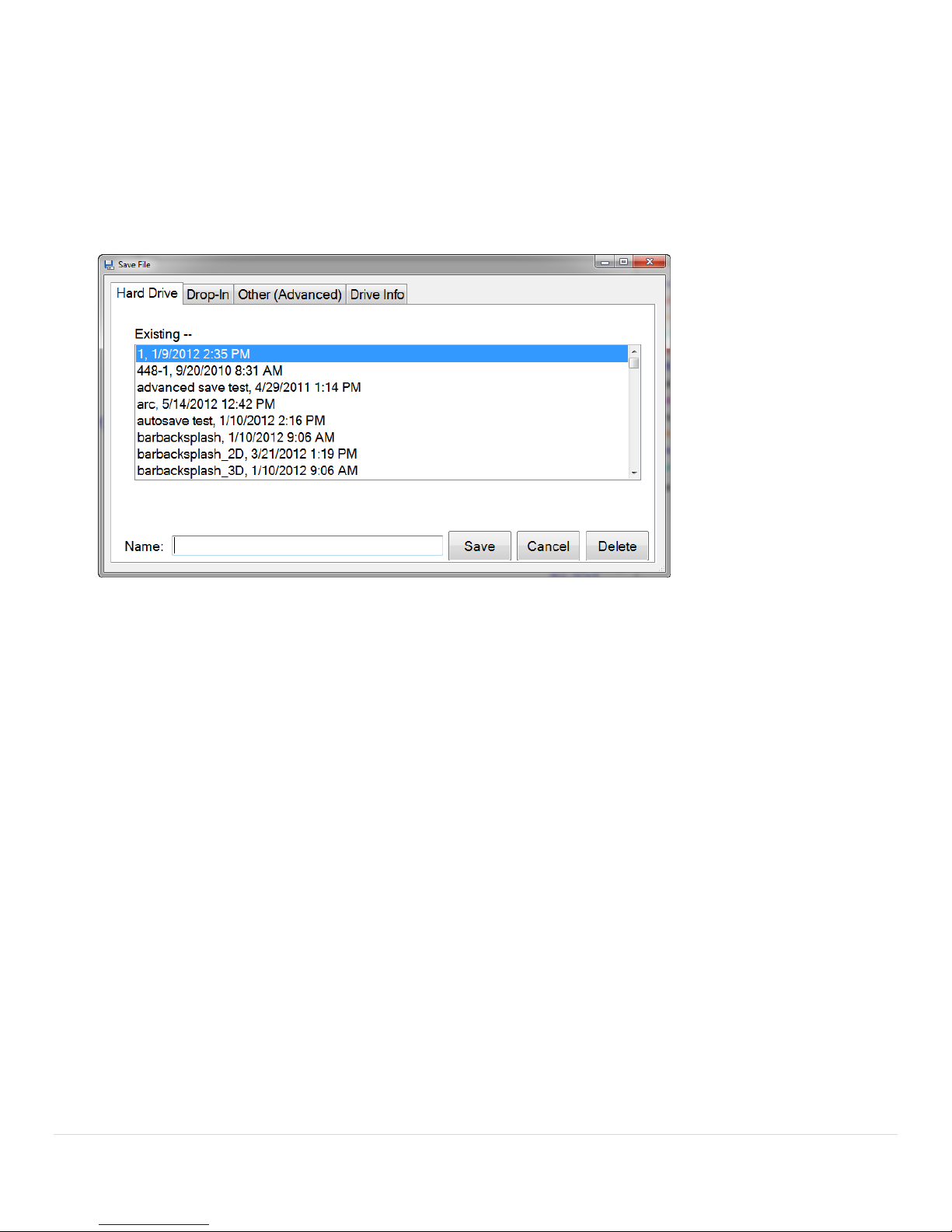
2.6 Save As
The first time you are saving a template, you should choose to Save As. This will bring up a box giving you the option to
save the template on the Hard Drive, as a Drop-In or using the Advanced saving option (Other).
2.6.1 Hard Drive
Saving files to the Hard Drive will place the jobs in the My Documents folder of the tablet.
2.6.2 Drop-In
If you create a Drop-In like a special corner, bump out or a sink bowl and you want to save it for future use, this is
where you will save it to. By saving here, the template will show up when you choose the 3TDrop-In3T feature.
13 | P a g e
2.6.3 Other (Advanced)
The Other (Advanced) method for saving templates should be used if you do not want to save your templates in
the My Documents folder or on your SD memory card. By using this option, you can save .dxf, .l55 (job files) or or
both files anywhere on the tablet that you want to (i.e. the desktop or a projects folder you created).
2.6.4 Drive Info
Drive Info shows the current status of the drives/storage devices on the tablet PC. This includes the hard drive, as
well as any SD cards and removable disk drives (flash drives).
2.7 Exit
Exiting the program will close the program and take you back to the Windows desktop. You should always make sure to
save changes to any job file you were working on before you exit the program.
When Exiting the program in conjunction with using the laser, the laser will shut off on its own if it is a pre-February,
2016 model. If Purchased Post-February, 2016, marked R4.1 on the bottom label, the laser will continue to remain on for
a couple more minutes. It will shut off on its own but if you wish to manually turn it off, hold the power button for 3
seconds.
2.8 Connect To Laser
The only time this will show up is if the tablet is not connected to the laser. If you look in the title bar of the program,
you will see "LT Disconnected" and there will be no interaction between the tablet and the laser.
If the tablet is connected to the laser via the USB cable and the title bar is showing "LT Disconnected" you can select
Connect To Laser. This will then establish a connection between the laser and the tablet. This process of connecting can
take up to 10 seconds.

14 | P a g e
Edit Menu
The Edit menu is where you will find the most basic editing options that will be performed when starting a new job,
saving a job, opening previous jobs and adding information of a job.
2.9 Options
2.9.1 General Settings
Here you can change general settings and functions with the way the program is run. The General Settings are
categorized by their purpose in the software.
Save Settings
HD Save Location is used to change the location job files will be saved on your Tablet PC or computer. Click on
the browse button “…” to the right of the dialogue box and choose the folder you want to save all job files in
by default. Click Clear if you wish to revert back to the default location of My Documents.
Days to keep auto save files simply allows you to change how long auto save files are stored on the hard
drive. These auto saved files are located in C:\Program Files\Laser Products\LT-55XL\auto_save. This defaults
to 10 day but can be changed to however long you wish to save them.
Save with page names, if checked while saving a job the resulting .dxf files that are saved with it will be titled
whatever the page name is for that drawing.
Default DXF Polylines, if checked will default all lines to Polylines instead of Line Segments. Some CNC/CAM
machinery will only work with one or the other. Check with your machinery to see if this should be checked or
unchecked for your specific shop setup.
Export PDF in black/white with edge treatments, if checked will export the drawings to a .pdf file in black and
white with the edge types labeled on them.
Save Template Images, if checked will save a screen shot of the drawing as a .jpg file and can be used as a
reference.
Use Color in DXF Layer, if checked the layer name within the .dxf file will be preceded with the name of the
color. Some CAD/CAM systems need to have this checked.
Export DXF BYLAYER, if checked will export the BYLAYERS if your CNC machinery needs it.
Use DXF on advanced save, if checked will default to saving a .dxf file on the Advanced Save instead of the
default .l55.
Sync DXF files when opening LT55 file, if checked will import any modified .dxf files back into the job file (.l55)
when opening. This is done if you have an employee that modified the files in another CAD program and you
want update the .l55 file.
The line thickness within the exported DXF file is the default line thickness in .dxf files after exported.
Settings Save Location is the default location that settings files are saved to.
DXF File Name Format is the formatting scheme for naming .dxf files once saved.

15 | P a g e
Create DWG files when saving a job is checked when your company wishes to use DWG instead of DXF
Create DXF files when saving a job is checked when your company wishes to use DXF instead of DWG
Print Settings
Print page details, if checked will include each individual page’s details on Estimates.
Prepend to PDF is where you can attached a company estimate sheet (or any other pdf document) in front of
the Print Sheet we create.
Prepend to PDF Description just describes what the file is that is being prepended.
Company Info and the Customer Agreement will be presented on each printout they do. Clicking the Edit
button next to each will open up Windows Notepad. You can either write a customer agreement into the file
or you can write you own and then save it.
Print Logo is the log that will be added to your Print sheet. This needs to be a .jpg image.
Shop Sheet Logo is the logo that will be added to your Shop Sheet. This needs to be a .jpg image.
Drawing Display Settings
Auto Scale Dimensions, if checked will automatically scale the dimensions when printed.
Dimension Font Size is default font size for dimensions and text.
Show Tips at Startup, if checked will present you with a tip when the LT-2D3D software opens.
Display Radii Text, allows you to specify how you want radii to be shown on the screen. The default is the
number for the radius and then “R” but if you want only the number you can delete the “R” after <radius>.
Display Area Legend, allows you to turn on or off the Area Legend in the bottom right corner of the drawing
area.
Ignore mirror when drawing text, if checked will allow text to be read legibly (not mirrored) while you are
drawing in Mirror Mode.
Use black background on drawing, if checked will make the default white screen black on the drawing canvas.
We added this because many CAD/CAM programs use black and we wanted to allow users to have it be the
same as they are used to.
Display Shortcut Text, if checked will show the text in the right menu. If unchecked, it will only show the icons.
Job Details Settings
Install Date Add will allow you to automatically add a set number of days to the Install Date based on the
Template Date.

16 | P a g e
Use Job Name as Email Subject, if checked will automatically fill the job name in the Subject line while selling
an email.
Import Job Mapping File, allows you to specify how you want to import job information into the program
based on what job tracking software you currently use to store customer information.
Set Install Days Automatically, if checked will automatically set the install date based on the Template Date.
Miscellaneous Settings
Drop-In Folder is used if you want to use a specific folder as your drop in folder. This is helpful if you don’t
want to see the sample sinks and marks we have included. Many users of will create a Drop In folder in My
Documents and save them all in there.
Remember Last Drop-in opens the drop-in menu to the last drop-in you used.
Auto shutoff wired LT-55 XL will turn off the laser to save battery after inactivity.
Zip files for Email when checked will zip all emailed files to compress them so sending is faster. When
unchecked, all emailed files will be sent unzipped.
Display Popup Calculator when unchecked will not pop up the number pad. This is mostly done on desktop or
laptops that have a keyboard available all the time.
Display Edge Type instead of Color changes Color in the right drawing menu to Edge Type for those
companies that do not specifically use colors but edge codes instead.
Display Radius Label on Drawing will automatically display all radius measurements when drawn.
Job Tracker Settings
API URL is the web address that is used to log in to Job Tracker on Moraware’s website. The address is
https://xyz.moraware.net/xyz/api.aspx where xyz is your company name.
User Name is your company’s Moraware Job Tracker log in name.
Password is your company’s Moraware Job Tracker password.
2.9.2 Estimate Settings
Here you can change the values used in your estimates. Area and perimeter can be modified based on what
treatment you assign to a specific color.
Group By Page, if checked, will allow the estimate option to group all the pages so that each page has its own
estimated values.
A Materials field has been added if you pass these costs onto the customer. Click the “+” button to add a new
line. Then click on the Material line and type in what you need to add. Similarly, click on the Cost line and
modify the cost to reflect the cost you associate with the material.

17 | P a g e
2.9.3 Quick Actions
Quick Actions are commonly used actions. These include fillets, radii and offsets that are used often.
To create a new action, follow the steps below:
1. Click Add New
2. Select the Action Type, Fillet Type, Unit of Measure, Amount/Font Size and Display Quick Action
Text Color
3. Choose if you want the Quick Action to be displayed in the main Quick Action menu by checking the
box or just in that individual’s action menu by unchecking the box.
To remove a previous created Quick Action, highlight the one you wish to remove and click Remove.
Default Quick Action Text Color allows you to make all the text the same color.
2.9.4 E-Mail Settings
If you choose to email your templated files back to your shop while you are at a jobsite, this is where you will
set up your email configurations.
The email settings are standard settings so please look at your personal email account settings and copy that
information over to these forms. If you are unsure of your email settings, please contact your email/internet
provider to obtain them. There are many email providers out there; we cannot keep track of everyone's
individual settings.
If you have a Gmail account, we made it easy for you. All you have to do is fill in your username (email
address), password and a From Name (your name). Then click on the Web button in the lower left corner and
follow the instructions there to allow our software to send email through your account by enabling POP in the
Gmail settings. The setting in our program will look like this:
Below are the most common email settings.
Gmail
SMTP Server: smtp.gmail.com
SMTP User: your email address
SMTP Password: your password
SMTP Port: 587

18 | P a g e
SMTP Secure: checked
From Address: your email address (same as SMTP User)
From Name: Your Name
You need to Enable POP Email in your GMail account. Instructions to do so can be found here:
https://support.google.com/mail/answer/13273?hl=en
You need to turn on “Less Secure Apps.” On the following page:
http://www.google.com/settings/security/lesssecureapps
Comcast
SMTP Server: smtp.comcast.com
SMTP User: your email address
SMTP Password: your password
SMTP Port: 587
SMTP Secure: checked
From Address: your email address (same as SMTP User)
From Name: Your Name
Hotmail
SMTP Server: smtp.live.com
SMTP User: your email address
SMTP Password: your password
SMTP Port: 587
SMTP Secure: checked
From Address: your email address (same as SMTP User)
From Name: Your Name
Yahoo (Required Yahoo! Plus Account (yearly payment))
SMTP Server: smtp.mail.yahoo.com
SMTP User: your email address
SMTP Password: your password
SMTP Port: 587
SMTP Secure: checked
From Address: your email address (same as SMTP User)
From Name: Your Name
MSN
SMTP Server: smtp.live.com
SMTP User: your email address
SMTP Password: your password
SMTP Port: 587
SMTP Secure: checked
From Address: your email address (same as SMTP User)
From Name: Your Name
AOL
SMTP Server: smtp.aol.com
SMTP User: your email address
SMTP Password: your password
SMTP Port: 587
SMTP Secure: checked
From Address: your email address (same as SMTP User)

19 | P a g e
From Name: Your Name
Network Solutions
SMTP Server: smtp.yourdomain.com
SMTP User: your email address
SMTP Password: your password
SMTP Port: 587
SMTP Secure: checked
From Address: your email address (same as SMTP User)
From Name: Your Name
2.9.5 Advanced
In the Advanced Options tab you can choose between any of the 11 languages we currently offer (English,
Brazilian Portuguese, Chinese, Czech, French, German, Italian, Polish CE, Polish UTF, Russian and Spanish).
Once you choose a new language you will need to restart the software in order to see the changes to the
language.
Associate l55 files with this application is used if when you double click on an .l55 file and it does not open up
in the Precision Laser Templator software. By clicking the “Associate” button, this will fix this.
Associate csv files with Open Office is used if there is ever a problem with opening estimate files in Open
Office.
Backup will save all your job files to another location. This can be done from the hard drive to an external hard
drive or from your SD Card.
2.9.6 Shortcuts
Shortcuts are used to quickly perform actions in the program. This is commonly used in Windows programs
like CTRL + O will bring up the open file function. CTRL + E will activate the Erase function.
2.10 Job Info / Pages
The 3TJob Info3T section is where you will enter information on each specific job that you template. This includes names of
customers, addresses, important dates, additional items used for the job and an agreement for your customers to sign.
2.10.1 General
3TGeneral3T information includes the name of the job you are working on. This can be designated by internal
reference numbers, bar code numbers or something as simple as the customer's last name.
2.10.2 Address
Address is the location of the job site, home or industrial location.
2.10.3 Dates
Template Date is the date which you and the customer decide to template the job (usually the current date).
Draw Date is used if an employee modifies the job file after it is template. If the templator is responsible for
modifying it onsite (adding offsets, radii, drop-ins etc.) this is unnecessary to use. However, if there is another
employee in the workflow, we believe it is important to know who has modified that file for accountability.

20 | P a g e
Approved Date is used to record the date in which the customer has approved the final product which is to be
fabricated. This could be at the customer’s house after the templator has template and modified the .dxf or it
could be at a later time.
Install Date is when you will install the counter tops. This can be used in conjunction with your scheduling
software so you can determine when the shop will be able to produce the counter tops and when your installers
will be able to deliver them to the customer.
Name is the person that preformed the specific job functions associated with the dates.
2.10.4 Additional Items
Additional Items is where you can list the cost of fixtures or other materials you will be charging the
customer. We have also created a Catalog where you can add items that you know will be used in the
future instead of having to enter them in each time.
1. Click Add
2. Type the description of the item
3. Enter the amount of the item
4. Click OK
We also allow you to create a Catalog of items that you use frequently. To use the catalog:
1. Click Catalog
2. Click Add New Item
3. Enter a Description and Amount
4. Click OK
5. Check the box of the items you want to add to this specific job
6. Click OK
2.10.5 Pages
Pages allow you to have multiple digitized templates of the job in their own space. For example if you
have templated a customer's kitchen countertops, and you need to do their bathroom as well, you can
add a new page. When saved, you will have the same job folder but the 2 portions of the jobs will be in
their own separate .dxf files.

21 | P a g e
Pages can be switched back and forth by clicking on the tab at the top of the drawings. Simply click on the Page
you wish to see.
If you click Edit Pages, you will have the option to edit information about each specific page. In the column on
the left, you can choose what page you want to edit.
Page Name allows you to name each page.
Preview will show you what is on each page.
Use DXF Polylines, if checked allows you to specify on a page by page basis if that top needs to be saved in
Polylines. Line Segments are the default.
Save Invisible Colors, if checked will save all geometry in the file even if the color is set to be invisible.
Notes can be added about each page. This is to be more specific than the notes on the main screen.
Sink Info and Cook top Info can be added to each page if they are required.
2.10.6 Notes
In the Notes tab, you can enter notes about the job. These are different from the individual page notes that will
appear on the Shop Sheets. See the Pages section for more information on that.
2.10.7 Agreement
In the Agreement tab, you can attach your own company policy dealing with warranties and liabilities for the
customer to read. Once read and the customer checks the box saying they read and accept the terms, they can
sign their name right below it. Their signature will be presented on every page of the estimate you run.
When you go to print out an estimate with all the job information, you can choose to include the customer’s
signature on all the pages or select specific ones (Estimate, Notes, Images [images of the actual .dxf files] and
Photos)
1. To use a custom agreement, go to My Computer
2. Double click on C:
3. Double click on Program Files
4. Double click on Laser Products
5. Double click on Laser Templator
6. Double click on CustomerAgreement.txt (copy and paste it if you already have it written)
7. Write the agreement you want in this file
8. When finished, save the file
2.11 Move Circle
Move Circle will take any circle you click on and then move it in the direction you click, leaving behind the original one.
This is used commonly for making the faucet and soap dispenser holes.
2.12 Split Line
Split Line is used when you need to finish an edge with two different edges. You will split the line into two based on a
setback amount and then change the color/edge type accordingly.

22 | P a g e
1. Click the line you want to split
2. Enter an amount to split the line from the front edge
3. You will see the line split with a yellow line appearing to show the split and press OK
2.13 Flip / Scale
Flip will allow you to flip a drawing horizontally, vertically or both. This would be sued for when you draw a custom
corner and want to flip it to use it on the opposite edge.
Scale allows you to quickly double or half the size of a drawing. You can also enter a custom percentage to scale it.
2.14 Add Photo
Adding photographs to you job can be a very valuable tool; you can use the built in camera on the tablet to take job site
reference pictures.
To take photographs with the tablet follow these steps:
2. Click Add Photo from the Edit menu
3. Click Start Camera
4. Point the back of the tablet at the area you want to photograph
5. Click Capture
6. To view the captured photographs, click View Images
These photographs will be located in the same folder as the templated .dxf and the estimate file.
2.15 Erase Segment
Erase Segment will erase one line segment. To erase a segment:
1. Click Draw
2. Click Erase Segment
3. Click on one end point of the segment
4. Click on the other end point of the segment
Remember, every line has 2 end points, as well as a midpoint. When a line intersects another line that is not at the
midpoint, it will create new end points and midpoints.

23 | P a g e
2.16 Erase All On Page
Erase All On Page will erase the entire template you currently have on your screen. This is similar to creating a new file,
but if you have saved it, the name will remain associated with the current file. If you Erase All On Page and then
template again followed by a save, the original template will be lost.
2.17 Split Object On Point
Split Object On Point allows you to take an entity and split it into two entities at a snap point where another entity
crosses it.
2.18 Units
Under Units, you can choose if you wish to measure in Imperial (Standard) or Metric and set the denominator or
decimal places.

24 | P a g e
View Menu
The View menu is where you will find the most basic actions that will be performed when starting a new job, saving a
job, opening previous jobs and adding information of a job.
2.18 Rotate Drawing
This allows you to rotate the drawing to any degree.
1. Click Rotate Drawing from the View Menu
2. Enter in the degree you wish to rotate the drawing and click OK
2.19 Mirror
I you Mirror the template you have made, it will flip it along its vertical access. This is used if you are digitizing a
template on the floor. You template it and then Mirror it so production is correct.
2.20 Object Info
Object Info show detailed information on objects you select.
2.21 Circle Diameter
Clicking in the center of any circle will show you the diameter of that circle in millimeters, inches and fractions, an inches
and decimals.
1. Click Circle Diameter from the View Menu
2. Click on a circle
3. The circle diameter will be presented to you.
2.22 Display Measured Points
If you select Display Measured Points, every point that was captured by the laser while templating will be shown on the
template by a black x.

25 | P a g e
A grey crosshair will also appear if the file you are looking at was templated with the and not just drawn. This represents
the location the laser was when the job was being templated.
2.23 Display Contiguous Breaks
By clicking on Display Contiguous Breaks, a box will be shown if there is gap between any 2 lines or arcs that are 1/4"
(.25") or smaller.
To turn on Display Contiguous Breaks:
1. Click View.
2. Click Display Contiguous Breaks.
As you can see in the example above, you can see the break in the lines.
Once the break has been connected, the boxes will disappear. This can be done with the Draw Line, Fillet or Extend
functions.
2.24 Display Polylines
Display Polylines show you what objects are polylines in your job file. Polylines are indicated by a double black border
around line within the drawing. Also if you will notice that there is the area measurement shown in the top left corner of
the polyline.

26 | P a g e
If you have an object that you believe should be a polyline but is not indicated as one, click on Display
Contiguous Breaks. If there is a break in the object, it will not be defined as a polyline.
2.25 Display Color Names
Allows the color names to be viewed and printed on the edges for customers that do not have color printers. This was
originally added for a customer that had a color blind employee that couldn’t see the different colors.
2.26 Display Area Legend
Allows the user to display or hide the area legend.

27 | P a g e
Draw Menu
Draw functions are used once a countertop or surface has been templated. This is primarily used for editing the
templated surface.
2.27 Re-Position Laser
When you encounter a jobsite where you cannot see the entire surface that needs to be templated like a pillar for
example, you can use the Re-Position Laser feature to obtain all the field measurements you need.
Position 1
1. Template the job from the first position as you normally would.
2. Click Draw.
3. Click Re-Position Laser.
4. Template 3 points that will be visible from the second position (position 2) after the laser has been moved.
These should be marked with a target or have a physical blemish that can be distinguished from both locations
and be at least 10 feet apart. As you are templating them, you will see red “x” appear with a number next to it.
This will help when you move to the second position.
Position 2
5. Pick up and move the laser to the second position making sure you can still see the 3 points you just templated.
6. Align laser to first of the three points (red laser hits the target) indicated on the screen by a red “x” and the
number “1”
7. Tap on the digital representation of the first cross on the screen. It will have the number “1” and a red circle
around it now.
8. Pause and make sure the Tablet PC chirps signifying that the measurement was received.
9. Align laser to first of the three points (red laser hits the target) indicated on the screen by a red “x” and the
number “2”
10. Tap on the digital representation of the first cross on the screen. It will have the number “2” and a red circle
around it now.
11. Pause and make sure the Tablet PC chirps signifying that the measurement was received.
12. Align laser to first of the three points (red laser hits the target) indicated on the screen by a red “x” and the
number “3”
13. Tap on the digital representation of the first cross on the screen. It will have the number “3” and a red circle
around it now.
14. You will see a confirmation that the laser has been properly repositioned and you can continue templating. If
not, it will ask you to re template the last three points again.
2.28 Set Plane
When starting a new job or page, LT-2D3D Laser Templator (Post-February, 2016) users will be asked to set the plane
that they will be templating on. Any new pages or jobs can be created without re-engaging the 2D lock. They will
be instructed to template three points on that plane. The plane would be a countertop, wall (backsplash) or
any other surface.
Clicking the “Show Example” button will bring up the following image showing where to position the three points. The
points only need to generally be in a left, right, back/top orientation to one another

28 | P a g e
The three points need to be at least 12” apart from each other and cannot be near to a straight line. If the three points
are set like this, you will see a warning box stating that the measurement’s accuracy will be affected. The user can then
choose to reshoot or accept them as is. We suggest that get the three points in a triangular pattern and have them be as
far apart as possible to the highest level of accuracy.
2.29 Offset
2.29.1 Offset Scribed Wall
To offset a scribed wall:
1. Key in the distance you want to offset the scribed wall and hit OK.
2. Select all parts of the wall you want to offset.
3. Select Done Selecting.
4. Click in the direction you want the wall to be offset just as if you were doing a normal offset.
2.29.2 Offset Polygon
Offset Multiple would be used if you want to offset an entire object outward or inward. This is commonly used in
the situation of a sink reveal. If you are using a under mounted sink and need to reduce the size of the opening in
the countertop because you are going to top mount it (different sink with same dimensions), you would drop in
the sink, select it and then reduce the size of the opening.
1. Key in the distance you want to offset and hit OK.
2. Select all parts of the object you want to offset.
3. Select Done Selecting.
4. Click in the direction you want the wall to be offset just as if you were doing a normal offset.
2.30 Define (0,0)
Define (0,0) is used for when you create a 3TDrop-In3T and need to designate a point where you want it to snap to
when you add it to a template. To 3TDefine (0,0)3T:
1. Click 3TDraw3T.
2. Click 3TDefine (0,0)3T.
3. Click the point you wish to designate (points will snap to end points, midpoints and intersections).
2.31 Slab Layout
When Slab Layout is clicked, you will need to tap on all the lines you want to move or modify.

29 | P a g e
Selecting lines is done one of three ways. You can individually click on each line segment or you can click and drag to
select all lines that inside the selection box. If you have used multiple colors on your job, you can click the drop down
box on, choose the color you want selected and then click the Select button. Only the color you choose will be selected.
Once selected, the selected lines will turn yellow-dashed indicating they have been selected. If you want to deselect all
the lines you have selected, instead of clicking on each line, you can press the Deselect All button. Below the Deselect
All button, you can also click the Erase Selected button which will delete all the selected lines.
From here you can use the Move section to move the selected lines in any of eight directs (up, down, left, right and any
directional at a 45º angle. The selected lines will be moved a set distance every time the Arrow buttons are pressed. This
distance determined below the Arrow buttons. If you wish to change this distance, you can click in the box and then use
the keypad to the right to determine the set distance.
If you want to rotate any selected lines you can either click the -45 or +45 buttons or you can change the angle in the
box below and click the + or – buttons to rotate those lines to that angle. There is also a wheel to the right of the Rotate
section that allows you to set predetermined angles in 45 increments (0 º, 45 º, 90 º, 135 º, 180 º, 225 º, 270 º and 315
º).
If you want to view a portion of the drawing that is off the screen, you can select the Pan check box. Once checked, you
can click on the screen and then drag it in any direction which will then move the drawing around on the screen.
You can move pieces using snap points.
1. Select the pieces you want to move.
2. Click Set Snap Point.
3. Click the point on the selected piece you want to snap to another point.
4. Click the point where you want to move the selected points to.
5. Click Move.
Once you are finished in Slab Layout, click the flashing Done button in the bottom right corner.

30 | P a g e
2.32 Backsplash
To add a backsplash to a countertop:
1. Click Draw.
2. Click Add Backsplash.
3. Enter the Height (or Full Height) and the Offset of the splash.
4. Click Ok.
5. Now click 2 points that will be then ends of the backsplash.
6. Finally click in the direction you want the offset to be. In this case above the line.
2.33 Angle
To add an angle:
1. Click 2 points that will define the ends of the lines.
2. Click the point that will be the vertex where the 2 lines will intersect.
2.34 Radius
Display Radii allows you do display the radius of an arch or circle. To display the radii:
1. Select the arc or circle you wish to have the radius displayed.
2. Click the location you would like that radius to be displayed at.
2.35 Dimensions
To add dimensions to a job:
1. Click Draw.
2. Click Add Dimensions.
3. Click 2 points that you want to use as end points of the dimensions.
4. Click away in the direction you want the dimension to be added to.
2.36 Maximum Dimensions
Maximum Dimension allows you to find the maximum lengths and widths of an object. To figure the maximum
dimension:
1. Select the 2 outer lines that you want to use as the outermost dimensions. Red arrows will show the objects you
selected.
2. Select Done Selecting. The arrows will turn green signifying they have been selected and are ready to be
measured.
Click in the area you want the dimension to be displayed.
2.37 Text
To Add Text:
1. Click 3TDraw3T.
2. Click 3TAdd Text3T.
3. Type in the text you want.
4. Tap on the screen where you want it to appear.
2.38 Center Line
To add a Center Line:
1. Click the line you want to add a Center Line to (this does not need to be the center of the countertops, it can be
the center of a sink, stove or anything else that will be dropped in).
2. Click the direction you want the center line to be based off of.
3. Enter an Offset Distance that will be from the front or right edge.

31 | P a g e
4. Enter a Set Back Distance that will be from the line you clicked on.
5. Press Ok.
6. A cross with dimensions showing the offset dimensions will be shown (you can erase these dimensions if you
want).
2.39 Line
While editing a template, there are 2 types of lines that can be drawn, 2 Point Line and 1 Point Line.
To draw a 2 Point Line:
1. Click Draw.
2. Click Draw Line.
3. Click 2 Point Line.
4. Finally click any 2 points. These can be end points, midpoints or intersections.
To draw a 1 Point Line:
1. Click Draw.
2. Click Draw Line.
3. Click 1 Point Line.
4. Choose the Line Length and Angle of the line you want to draw.
5. Finally click any point. This can be an end point, midpoint or intersection.
2.40 Arc
While editing a template, you can draw an arc by clicking any 3 points. To draw an Arc:
1. Click Draw.
2. Click Draw Arc.
3. Click any 3 points. These can be end points, midpoints or intersections.
2.41 Circle
While editing a template, there are 2 types of circles that can be drawn. 3-Point Circle and 1-Point Circle.
To draw a 1-Point Circle:
1. Click Draw.
2. Click Draw Circle.
3. Select 1-Point and enter a Radius value.
4. Click on the template and that will become the midpoint of the circle.
To draw a 3-Point Circle:
1. Click Draw.
2. Click Draw Circle.
3. Select 3-Point. Radius is not important because you will be selecting 3 points on your template to create the
circle and then it will be automatically figured.
4. Click on any 3 points in the template and a circle will be created running through all 3 selected points.

32 | P a g e
2.42 Circle
While editing a template, there are 2 types of circles that can be drawn. 3-Point Circle and 1-Point Circle.
To draw a 1-Point Circle:
2.43 Ellipse
To draw an ellipse:
1. Click Draw.
2. Click Ellipse.
3. Enter the Horizontal Radius (how wide it is left to right) and Vertical Radius how tall it is (top to bottom).
4. Click anywhere on the template.
2.44 Cross
To draw a Manual Cross:
1. Click Draw.
2. Click Manual Cross.
3. Click anywhere on the template and a cross will be created.
2.45 Custom Box
Adding a custom box is use when you want to insert a standard sized box. Most often when there is an island that you
do not want to template but you have a standard sized shape that needs to be added to a drawing.

33 | P a g e
2.46 Menu Bar Functions
2.46.1 Laser On
If the tablet is connected to the laser, click Laser On and the laser will turn on.
2.46.2 Start New Line
While templating and measuring points, after you have taken 2 points (which will draw a line), click Start New Line
if you wish to start a new surface. This would be used when you have taken 2 points on one side of a cabinet base
and then you move to the front or back of the cabinet base.
If you do not hit Start New Line, a chamfer will be drawn connecting the 3rd and 4th points.
2.46.3 Laser Off
If the tablet is connected to the laser, click Laser Off and the laser will turn off.
2.46.4 Zoom
While you are editing the template, you can Zoom in and out to get into close areas that you need to be enlarged.
This can be done 2 different ways.
+ & -:
1. Click the + button and the drawing will zoom in.
2. You can click and drag the screen around to move to the area you want to.
3. Once finished, you can click the -button and you will zoom out.
2-Point Zoom:
1. Click Zoom.
2. Click 2 points on a diagonal in which you want to be the top and bottom corners.
1. The easiest way to do this is think about top right and bottom left or top left and bottom right
corners.
2.46.5 Best Fit
While you are zoomed in on a specific area while editing, you can click Best Fit and the template will be zoomed in
or out so that the entire drawing is fit within 90% of the window.

34 | P a g e
Templating Menu (Right Sidebar)
This menu is used while you are actually doing the templating and taking measurements.
2.47 Laser Mode
There are 4 drawing modes to use while templating, Line, Arc, Circle and Cross.
Line - This is the default mode that will be set up each time you open our software. Every 2 points measured will create
a line.
Arc - Every 3 points will create an arc.
Circle - There are 2 types of circles that can be drawn, 3-Point and 1-Point.
3-Point - This type of circle is used when there is a column or anything stationary that you have to template and has
to be precisely on. All you need to do is measure 3 points and the software will create a circle based on those 3
measurements.
1-Point - This type of circle is used when you are going to be putting a grommet in. The exact position is not
necessary, only the size of it. Input the radius of the circle and the next measured point will be the center of the
circle. Remember a radius is 1/2 of a circle so if you do a 2-inch radius, the circle will be a 4 inches in diameter.
Cross - Drawing a cross will simply put a cross on the measured point. This is especially useful for drop-ins, marking
center lines, as well as use with the Re-Position Laser (Leap) feature.
2.48 Erase
Clicking Erase will allow you to erase any line segment you have templated or drawn.
2.49 Distance
Using the Distance feature allows you to measure from any one point to any other point.
1. Click Distance.
2. Click 2 points on the template.
2.50 Auto Fillet
Using the Auto Fillet feature allows you to speed up your templating. You no longer need to click Start New Line when
you are moving to a new plane. This is because every third point taken will start a new line.
For example, you will take 2 points on the side of a cabinet base creating a line. The third point will then be taken on the
front of the cabinet base. Once the forth point is taken and you have to lines drawn, those are then automatically
filleted to each other creating a corner.
2.51 Fillet
Fillet allows you to add in special corners to templates. This includes corners that have been drawn in already as well as
corners that have been left open while templating.
There are 3 different types of fillets that you can add (Radii, Chamfers and Sharp Corners).

35 | P a g e
Radius - When you choose to fillet a radius, the software will automatically figure the intersection of the 2 lines and then
back off that many inches and ad the radius edge.
Chamfer - Like a radius, a chamfer will do the same only draw a chamfered edge connecting the 2 points with an angled
line.
Sharp Corner - This is the simplest of the 3 fillets. A sharp corner will simply extend the 2 drawn lines until they meet
forming a corner.
To add a Fillet:
1. Click Fillet.
2. Choose Radius, Chamfer or Sharp Corner. (If you choose Radius or Chamfer choose the size you want to use.
3. Click OK.
4. Click on the two lines you want to fillet. Once a line is selected it will turn gray.
When you are filleting a, any part of the lines that would normally extend past filleted intersection will be removed.
There is also a quick selection bar on the right side that offers you commonly used choices that can be edited by the
user.
2.52 Offset
To use the Offset feature:
1. Click Offset.
2. Enter the distance you want to offset.
3. Select the line you want to offset. The line will turn gray showing it has been selected.
4. Click away in the direction you want to offset the line.
2.53 Rotate
Once you have finished templating your job, you can use the Rotate feature to rotate it to be square with the surface
you are editing. This should be done before any object is dropped in like a sink or dishwasher.
1. Click Rotate.
2. Select the edge you want to be square. All other parts of the template will be rotated in relation to the selected
line.
It is very important that when you drop in any object like a sink that you rotate the edge that it will be sitting on. If it
is not, you will end up with the countertop edge and the drop-in not being parallel to each other. This is due to the
fact that the majority of cabinet bases and walls are not on a perfect 90º with each other. So if you are going to add
a sink and dishwasher you will need to:
1. Rotate the front edge for the sink.
2. Drop-in the sink.
3. Rotate the front edge for the dishwasher.
4. Drop-in the dishwasher.

36 | P a g e
2.54 Extend
When 2 lines do not connect, 1 of the lines can be extended to meet the other.
1. Click Extend.
2. Select the line you want to extend to. It will turn gray to show that it has been selected.
3. Select the line you want to extend.
2.55 Draw Segment
To draw a line from two points:
1. Click Draw Segment.
2. Select a point and select the second point.
2.56 Dimensions
Clicking Dimensions will bring up the dimension of every line templated. To remove the dimensions just click on
Dimensions button again.
You can edit the way the dimensions will appear by going into the View menu and changing how the software will
display measurements.
2.57 Color
Color will present you with a screen where you can choose the color you want to template with. It also allows you to set
the default color that will be used when taking measurements.
Edge Type can be changed if you double click in the field next to the color.
Line Type can be changed from Continuous to Dashed depending on if you want to use the color to cut off of or as a
reference line.
The Visible check box is used if you want to hide certain colors from view. These are commonly measurements that
don’t need to be seen once you move to production on CNC machines.

37 | P a g e
Amount is used to give a value to the linear length of an edge type being used. (e.g. charging $5 per linear foot of an
ogee edge).
Seam allows the user to designate if a color is a seam line. This is helpful when using Slab Layout allowing you to split
parts of the job along that seam line. The program knows that a seam line will need to be split and duplicated so that it
keeps the line on both pieces.
Default colors are used so that when you initially open the program on a jobsite, you will always have the colors set the
way you intend to use them. This way, you don’t need to define the color for Dimensions, Backsplashes or Text on each
job.
New Color will allow you to add a new color to your pallet while Remove Color will remove whatever color is highlighted
when it is clicked.
Revise allows you to change the color of previously drawn lines by clicking on the color you want to use, then pressing
Revise and taping on the entities you want to change. Revise All does the same only it will change every line’s color to
the chosen color.
2.58 Drop-In
Pre-saved .dxf items can be used as a Drop-In. Mainly sinks and edges are used with the feature but you can add
anything you want. This would include marks to signify edge treatments, center lines for sinks or anything else you want
to design.
1. Click Drop-In.
2. Select the drop-in you want to use from the list on the left.
3. Select the color you want to have the drop-in be presented in.
4. Rotate the dropping to the angle you want it and click OK.
5. Select the line you want the drop-in to be on. Remember that you need to first rotate that edge so that when
you drop in the sink they will be parallel to each other.
6. Lastly, you can offset the sink back away from the edge you placed it on.
1. Click Offset.
2. Enter the distance you want to offset the drop-in.
3. Select the sink you want to be offset. A message will ask "Would you like to move the entire drop-in?"
4. Click Yes. The sink will turn gray to show you selected it.
5. Click in the direction you want to offset the sink.
Drop-ins are located in the following path: C:\Users\{UserName}\AppData\Roaming\LT55-XL\v2.0\Templates
2.59 Quick Action
The Quick Action feature is used to store your most commonly used actions. To use the Quick Action feature:
1. Click Quick Action.
2. Select the action you want to use from the list.
3. Use the Quick Action as you normally would.
2.60 Undo
Undo simply take one step backwards to your previous action. This can go as far back as 20 times. So you can Undo 20
actions.
2.61 Redo
Redo 3Tsimply takes a step forward after an Undo. So if you clicked 3TUndo3T and went backwards too far, 3TRedo3T will move
you forward in your progression.

38 | P a g e
3.0 BLUETOOTH PAIRING
3.1 Pair Laser to the Tablet PC (Pre-February, 2016)
1. Turn on tablet PC
2. Once finished booting, plug in USB cable and wait until you hear a kerplunk sound indicating it has
connected.
3. Click Start (Windows logo) and type Devices and Printers. Click Enter
a. Click Add a device
b. Turn on the Laser by pressing the power button.
c. A green LED will light up on the side indicating it is on.
4. You will see a device appear that is first named “Other,” “Unknown,” but will quickly change to “LT55-
XL,” “Laser,” or “Disto #####.”
5. Click on that device and then click Next.
6. Enter the device’s passcode of 0000 and click Next.
a. You might see an error saying “That passcode isn’t right. Try adding your device again.” If that
happens, click Close and try to add it a second time.
7. Right click or click and hold on the newly added device and click Properties.
8. Click the Hardware tab and look for the COM# for the laser and record it.
9. Click Start (Windows logo) and type Device Manager. Click Enter.
10. Click the triangle before Ports (COM & LPT)
11. Look for USB Serial Port (COM#)
a. Take note of what COM Port # the encoder is connected through. In this example it is COM5
12. Look for Standard Serial over Bluetooth link (COM#)
a. Take note of what COM Port #’s the laser is connected through. In this example it is COM 3 and
COM4. We want to use the one that was listed above in step 8.

39 | P a g e
3.2 Setting Comports (Purchased Pre-February, 2016)
1. Open the Laser Templator program
2. Click File / Help / Setup Device
a. Double click in the box to the right of Laser Connection.
b. Double click on the correct COM Port # from the steps above.
c. Double click on the box to the right of Encoder Connection
d. Double click on the correct COM Port # from the steps above.
3. Click Connect and wait for the laser to connect.
3.3 Pair Laser to the Tablet PC (Purchased Post-February, 2016, marked R4.1 on the
bottom label)
1. Turn on tablet PC
2. Once finished booting, plug in USB cable and wait until you hear a kerplunk sound indicating it has
connected.
3. Click Start (Windows logo) and type Devices and Printers. Click Enter
a. Click Add a device
b. Turn on the Laser by pressing the power button.
c. A green LED will light up on the side indicating it is on.
4. You will see a device appear that is first named “Disto ######”
5. Click on that device and then click Next.
6. Click Start (Windows logo) and type Device Manager. Click Enter.

40 | P a g e
7. Click the triangle before Ports (COM & LPT)
8. Look for USB Serial Port (COM#)
a. Take note of what COM Port # the encoder is connected through. In this example it is COM5
3.4 Setting Comports (Purchased Post-February, 2016, marked R4.1 on the bottom label)
1. Open the Laser Templator program
2. Click File / Help / Setup Device
a. Double click in the box to the right of Encoder Connection.
b. Double click on the correct COM Port # from the steps above.
3. Click Connect and wait for the laser to connect.

41 | P a g e
4.0 METHODS OF USE
4.1 Tripod Setup / Mounting
The laser is mounted to the level base by means of the metal stud. Once this stud is inserted in the level base, tighten
the screw to hold it in place. This screw should be tight at all times while the unit is in use.
The level base also has two large adjustment knobs for leveling (pre-February 2016 models). The laser can be adjusted
so that it is in the same plane as the surface you are templating (the most common scenario), or adjusted to a level
plane. Level vials are located on the top of the LT-2D3D base. Remember, level is not as important as being in the same
plane as the surface you are measuring.
Do not raise or lower tripod if you intend on templating in 3D. Doing so will result in inaccurate measurements.
The folding table tripod should have its legs fully unfolded and horizontal when in use. This tripod allows the laser to
function in the same manner as the standard tripod however it will allow the laser to be mounted into smaller areas like
on top of a countertop for measuring backsplashes.
4.2 Jobsite Placement
One of the most important things to do before you template a job is to place the laser in the correct location. Try to
visualize a location where most if not all points that need to be measured can be seen. This will allow you to place the
laser in the location with the highest probability of no needing to reposition the laser.
4.3 Targets
4.3.1 Pin Targets
Pin Targets are used when you are trying to measure a surface that would normally have a very drastic angle
(anything under 20°). Place the target where you want the measurement to be and then rotate the pin so that the
front flat surface faces the laser.
4.3.2 “T” Targets
“T” Targets are like the top portion of Clamp Targets only the vertical portion of it is split down the middle and
bent downward. This makes it very easy to butt up against a cabinet base or countertop.
4.3.3 Clamp Targets
Clamp Targets are used when you are templating the front surface of a cabinet base and you want to measure it
with a predefined overhang or set back. Place the target on the cabinet base and the slide it forward or backwards
to match with the overhang or setback distance you want.
4.3.4 Black Shields
The Black Shields are not actually targets but are used when templating and worried about targeting. Sometimes
while templating you will see reflection. Reflection is when the laser bounces off the surface you are measuring to
and is visible on another surface. The laser can pick up both of these laser dots and can give you inaccurate
measurements. To stop this, place a Black Shield to prevent reflection and then take the measurement.
4.4 Causes of Bad Measurements
4.4.1 Reflection
See 5.3.4 Black Shields. As stated before. Reflection occurs when the laser beam bounces off one surface and is
visible on another. The reason that this could cause bad measurements is that the sensor will see two dots at

42 | P a g e
different distances away from itself. To prevent reflection, try to place the laser beam about 3” away from a
corner, directly in the corner and then again 3” away from the corner. This way you will be able to get an accurate
measurement of both walls and account for any drywall mud build-up.
4.4.2 Drastic Angles
Drastic angles will cause the laser dot to become elongated. The longer this dot becomes the more of likelihood
that a measurement might be incorrect. Try to keep the dot to no longer than 1” in width. Beyond 1”, consider
placing the laser in a different location or using a target to prevent the elongated dot.
4.4.3 Dirty Lens
Just like the lens of a camera, it is important to keep the lens of the laser clean to ensure proper measurements. It
is recommended that before each job you check the lens to make sure there are no fingerprints or other smudges
present. If necessary, use the included microfiber cloth to clean the lens.
4.5 Micro Adjust
The Micro Adjust allows the user to make finer adjustments to the laser beam location on the surface you are
measuring.
4.5.1 Mounting on Tripod
When attaching the LT-2D3D to the tripod, position the horizontal micro adjust knob so that it is in a convenient
position as it will remain stationary relative to the tripod.
4.5.2 Usage
The micro adjusts for horizontal and vertical movement are engaged by pulling the black knurled knobs outward
and disengaged by pushing them in towards the unit. The micro adjusts should always be disengaged when
moving the laser manually.
4.5.3 Adjusting Tension
The tension for the micro adjust knobs can be adjusted with a small flathead screwdriver. The screws for these are
located just next to the respective micro adjust knob, on the flat side of the plates.
When adjusting the tension on either the manual movement or the micro adjusts, small changes will have a large
affect. Also, changing the manual movement tension will likely require the micro adjust tension to be adjusted as
well. If you notice the micro adjust slipping, loosen the tension on the manual movement setscrew slightly.
The tension for manual movement of both the horizontal and vertical axes can be adjusted via set screws using a
0.050" hex driver. The set screw for the horizontal movement is on the bottom of the unit, between the level vial
and tripod mount. The set screw for vertical movement is just below the 2D lock knob.
4.6 Micro Adjust
The Micro Adjust allows the user to make finer adjustments to the laser beam location on the surface you are measuring

43 | P a g e
5.0 POWER INFORMATION
5.1 Battery Life
The battery life will vary based on usage. Typically, this can be up to 8,000 measurements between charges.
When the battery is low on voltage, the ‘Low Battery’ LED will blink red. It is recommended that you save your current
progress and begin charging the laser when possible at this point. The laser can still be used while charging.
5.2 Battery Indication LEDs (Pre-February, 2016)
On the side of the laser, there are 3 LEDs that have different colors to them. Each one is described below.
Power LED
Green – Laser is on
Low Battery LED
Red Flashing – When the battery is low
Charging LED
o Red – When the charger is first plugged in and is determining the temperature and status of the
batteries it will stay red if the batteries are too cold and then turn amber once they warm up enough.
Usually you cannot see it go from red to Amber when you first plug in the laser.
Amber –Charging
Green – Done charging
For longest life on batteries, charge the laser completely (Green), use until empty (Red) or close to empty (Red Flashing).
5.3 Battery Indication LEDs (Purchased Post-February, 2016, marked R4.1 on the bottom
label)
On the side of the laser, there are 2 LEDs that have different colors to them. Each one is described below.
Power LED
Green – Laser is on
Low Battery LED
Red Flashing – When the battery is low (approximately 15%). The laser will also make three quick beeps once
a minute when the battery is below this level.
Charging LED
Red – When the charger is first plugged in and is determining the temperature and status of the batteries it will
stay red if the batteries are too cold and then turn amber once they warm up enough. Usually you cannot see it
go from red to Amber when you first plug in the laser.
Amber – Charging
Green – Done charging
For longest life on batteries, charge the laser completely (Green), use until empty (Red) or close to empty (Red Flashing).
5.4 Charging at Home and in a Car
The laser can be charged by plugging the supplied charger into the jack on the laser head. The ‘Charging’ LED on the
laser head will display the current status. When the charger is first plugged in, the ‘Charging’ LED will briefly be red while
it is determining the battery’s condition (this may be so brief that you cannot see it). The LED will then change to amber
while it is charging the battery. When the battery is fully charged, the LED will change to green.
The supplied tablet computer should be charged in accordance with the instructions in its documentation.

44 | P a g e
Only use the supplied chargers for both the laser and tablet computer. The use of other chargers may void the warranty
and cause damage to the components.
Charging the laser, tablet computer, or both in a car should be done with an appropriate inverter. A 250-watt inverter is
sufficient to charge both simultaneously. Refer to the inverter’s manual as it is sometimes necessary to wire it directly to
the car’s electrical system rather than through a cigarette lighter plug.
5.5 Normal Power Off Procedure
Lasers produced before 2/22/16 are programmed to turn off when the user exits the software.
If the laser is turned on and left to sit for 6 minutes without being connected to the tablet PC, it is programmed
to turn off to save power.
Lasers produced after 2/22/16 are programmed to turn off within three minutes of exiting the program
automatically. The user can also hold the power button for 3 seconds and the laser will turn off.

45 | P a g e
6.0 GENERAL INFORMATION
6.1 Warranty Information
Covered
Laser Products Industries (LPI) guarantees the LT-2D3D/LT-55 XL to be free from defects in material and workmanship
under normal use and services and will meet the following specifications while being operated under normal conditions
as defined in the training material supplied and/or the training provided by the staff of LPI.
Specifications
1. Accuracy of any measurement of ± 1/16” for measurements up to 50 feet on industry standard surfaces.
a. Accuracy guarantees apply to the measurements shown on the LT-2D3D/LT-55 XL and the associated
output files only; LPI cannot guarantee the accuracy of any ancillary equipment used in conjunction with
the LT-2D3D/LT-55 XL.
2. Capability of measuring up to 325 feet under ideal conditions.
3. Battery life of a minimum of 50 hours for the LT-2D3D/LT-55 XL.
4. Battery life of the supplied computer in accordance with the manufacturer’s specifications.
5. Compatibility of the output .dxf, .dwg, .pdf, .csv, and .jpg files.
6. Software second license compatibility with supported hardware and software.
7. Tablet operability in conjunction with the LT-2D3D/LT-55 XL.
Not Covered
This warranty does not cover equipment that has been lost, stolen, damaged by natural disaster or resulting from
unauthorized modification nor does it cover any malfunctions or damage deemed abuse or misuse.
Duration
This warranty is valid for one (1) year from the original date or purchase from LPI or one of its distributors.
Warranty Determination
Should the LT-2D3D/LT-55 XL or one of its components’ specifications fall into question, LPI reserves the right to operate
it in the presence of the customer either in person or through remote support to verify. If any component is shown to
not meet the stated specifications, LPI reserves the right to repair or replace any defective component at no cost,
provided the product is under warranty.
Obtaining Warranty Service
To obtain warranty service, you must first contact our Service Department so we can schedule a return on the product
and if needed, send a loaner unit during the repair period. The LT-2D3D/LT-55 XL must be returned in its original
packaging and include your contact information in the event that we need to contact you before we preform repairs.
Include, your name, company name, return address, and phone number. Any returned equipment must be complete
with all accessories and packaging and is subject to a fee based on the condition and completeness of the unit.
LPI will provide a loaner LT-55 XL/LT-2D3D and/or tablet computer, if needed, should your unit need to be sent in for
repair. Laser Products includes free shipping (UPS Ground) on all repairs/exchanges. Return shipping to LPI is
responsibility of the customer.
Transferability
This warranty is transferrable to another company only after written approval by LPI.

46 | P a g e
6.2 Laser Safety Guidelines
These guidelines are for your own protection and that of others around you. Lasers have a unique set of dangers not
present with other equipment common at work or at home.
Like most laser point devices, it is important to exercise caution with operating this device.
Never look into the beam of this or any other laser. This also includes pointing it at others around you.
Always turn off the laser beam when it is not being used to avoid accidental eye exposure.
When adjusting or aligning a laser, beware of reflections from all surfaces.
Never randomly aim a laser at other people. Although this laser is low power, direct eye contact should always
be avoided. This is a tool just like any other power tool on a job site and should be treated that way.
Instruct anyone else with you as to the hazards of laser light and make sure they understand all of these
guidelines. Those with you may actually be in MORE danger because you will know what to expect and what to
avoid unlike them.
This product conforms to IEC Regulations
6.3 Using the Computer with Other Programs
The computer that comes with this laser runs a full installation of Windows and can run most Windows compatible
programs. However, installing any programs other than those that are installed at the time you receive it can alter or
hinder operations and functionality. We strongly suggest you only use this tablet for templating and other related
functions.
We do not support the Laser Templator software on domains for networked usage. We will try to help where needed
but cannot guarantee we will be able to solve issues outside of the core functionality of the software.
6.4 Cleaning / General Care and Storage
The LT-2D3D are precision measurement tool and needs to be treated with care. Please follow the guidelines below.
Make sure the lens of the laser is clean before starting every job. Finger prints and smudges can affect accuracy
of the laser.
Handle the tablet PC with care. This is a computer and like all computers, if they are treated roughly, the internal
components or outside casing can be damaged.
o As stated above in the warranty, misuse / abuse is not covered in the warranty which include but are not
limited to:
Cracked / broken screens.
Over-rotated screens (on tablets that have them) caused by rotating in the wrong direction or
going past the point in which they are supposed to be stopped.
Dropping any part of the device leading to cracked outside housing or damaged internal
components.
6.5 LT-2D3D Laser Templator Specifications
The LT-2D3D software was designed to be used on any current Windows computer (Windows XP, Vista, 7, 8, and 10).
We have heard of customers using it on Windows Server 2000, 2003 and 2008 however we have not tested this nor do
we support it. If you choose to install the software on a server, we offer no support.
LT-2D3Ds built after 2/15/2016 are do not use a leveling base anymore. Because of this, you can use this laser on any old
tripod that doesn’t have a leveling base. However, you CANNOT use an older LT-55 XL/LT-2D3Ds on a new tripod that
came with one of these LT-2D3Ds.

47 | P a g e
6.6 Training Videos
With the purchase of every LT-2D3D Laser Templator, training videos are included. Please watch those videos to learn
how to use this digital templating system properly. This user manual is meant to be a quick reference and used in
conjunction with the videos but is not meant to replace watching those training videos. They can be viewed on our
website as well at http://laserproductsus.com/videos/

48 | P a g e
7.0 TECHNICAL INFORMATION
7.1 Accuracy and Distance Specifications
Accuracy of +/- 1/16" up to 50 feet on industry standard surfaces
Capable of measuring up to 200 feet to industry standard surfaces
Capable of measuring up to 600 feet using an appropriate target under ideal conditions
7.2 Storage and Operating Temperatures
Storage: -4 °F to 113°F (-20°C to 45°C) (LT-2D3D Laser Templator)
Operation: 32°F to 113°F (0°C to 45°C) (LT-2D3D Laser Templator)
Storage: -4 °F to 95°F (-20°C to 45°C) (Tablet PC)
Operation: 32°F to 95°F (0°C to 45°C) (Tablet PC)
Minimum temperature required to charge the batteries: 32°F (0°C)
7.3 Laser Specifications
635nm
<1mW
Class 2 Laser Product
Complies with 21 CFR 1040.10 and 1040.11 except for deviations pursuant to Laser Notice no. 50, dated May
2001, with IEC 60825-1 (2001) and EN 60825-1.

49 | P a g e
8.0 CONTACT INFORMATION
Laser Products Industries
1344 Enterprise Dr.
Romeoville, IL 60446 USA
P: 630-679-1300
F: 630-679-1356
http://laserproductsus.com
info@laserproductsus.com
Countertop, Glass Industry
Matt Thomson – 630-390-0439 – North East – (CT, IN, KY, MA, MD, ME, MI, NH, NJ, NY, OH, PA, RI, VT, WV)
Matt Drnec – South East – (AL, SC, FL, AR, GA, LA, MS, NC, TN)
JT Hoffmann – 630-679-1300 – Mid West – (IL, IA, KS, MN, MO, ND, NE, OK, SD, TX, WI)
Jeff Larson – 303-378-3839 – West – (AZ, CA, CO, ID, MT, NV, OR, UT, WA, WY)
Aatif Markar – 647-221-0467 – Canada and Middle East
Carl Sharkey – +44 (0) 1274 412597 – Europe/Russia
Industrial Fabric Industry
Drew Thornton – 256-734-0732 – Entire United States

50 | P a g e
9.0 REGISTRATION
In order to service your laser, we need to make sure we have all of your company information. Please take a moment to
fill out the information below so that we can better understand your company and serve your needs. This can be faxed
(630-679-1356), emailed (info@laserproducstus.com) or mailed to us (1344 Enterprise Dr., Romeoville, IL 60446)
General Information
Company Name: ___________________
Owner: ___________________
Templator’s Name(s): _______________________________________________________________________________
Address: ______________________________________
City: ___________________ State: ____ Zip: _________
Phone: ___________________ Fax: ___________________
Website: ______________________________________
Email: ______________________________________
LT-2D3D Serial Number: ___________________
Fabrication Information (Please circle all that apply)
Production Information: Automated Plant Fab Center CNC Router CNC JetSaw CNC Saw CNC WaterJet Bridge
Saw Outsource Fabrication Training Facility
Kitchens/Jobs Per Week: ____
CAD Experience: Beginner Intermediate Advanced
Associations you are a member of: AWFS ISFA MIA NKBA SFA WFCA IFAI MFA PAMA
Other: ___________________
Other Digital Templating Products Used: ________________________________________________________________
 Loading...