

Page 1

NOTICE
For Firmware (V1.1 and later version), when under the
Single File Mode, the file can be repeated if you choose
to redo it. After the work is completed, the machine
will be back to the “STOP” status. The same file will
be processed again if you press the “START” key again.
One thing that has to take into consideration is that the
file size has to be smaller than 15.9 MB (if memory
buffer for your machine is 16 MB) or 63.9 MB (if the
memory buffer you have is 64 MB). If you choose to
start with a new file, you would have to press the “DEL
FILE” button twice to clear out the memory. Then the
machine will be ready to receive new data again.
Page 2

2
Content
UNPACKING
QUICK MENU
LENS and MANUAL FOCUS GAUGE
I. INTRODUCTION
Principles of CO
2
Laser ---------------------------------- 7
Safety ------------------------------------------------------- 7
Front View ------------------------------------------------- 9
Back View ------------------------------------------------- 10
Motion System -------------------------------------------- 11
II. RECOMMENDED CONFIGURATION
Computer--------------------------------------------------- 13
Scanner ----------------------------------------------------- 13
Software ---------------------------------------------------- 13
III. HARDWARE INSTALLATION
Cabling Connection--------------------------------------- 14
Exhaust Vent----------------------------------------------- 15
IV. SOFTWARE INSTALLATION---------------------- 16
V. OPERATION
Environment ----------------------------------------------- 17
Flexible Utility of Your Memory Buffer--------------- 17
Multiple File Mode / Single File Mode ---------------- 18
Start to Operate-------------------------------------------- 19
Control Panel ---------------------------------------------- 20
Software Operation -------------------------------------- 39
VI. BASIC MAINTENANCE ------------------------------ 50
VII. TROUBLE SHOOTING ------------------------------- 53
APPENDIX
I. Specification
II. Tip for 3D Application
Page 3

3
UNPACKING
Caution:
! The weight of LaserPro VENUS is about 32 kg (70 ponds).
! Please save the original shipping carton in case any returning service is needed.
! Please inspect what you have received from the shipped carton by comparing
with the following listed items.
I. Unpacking inspection
Your package should contain the following items:
ITEM QUANTITY
Cleaning Set
cotton swab
lens cleaner
lens tissue (lint free)
1 pack
1
1
1.5” Manual Focus Gauge (blue color)
1
AC Power Cord
1
Print Port Cable
1
LaserPro VENUS Driver
1
Mirror (for Mirror#2, #3)
1
Engraving Samples 1 pack
Page 4

4
QUICK MENU
1. Connect air exhaust system.
2. Setup computer and connect with engraving system properly.
3. Turn ON host computer system.
4. Install the Venus Driver. (for the first time use only)
5. Use Windows-based program (such as CorelDRAW, PhotoShop, PhotoPaint,
Illustrator, CASmate, Signlab, EasySign, AutoCAD, etc.) to operate with the
engraver.
6. Turn ON engraver. The working table moves down 50mm approximately and
the lens carriage moves to the home position (upper left corner) after system
initialization.
7. Auto-focusing: under STOP status, put work-piece on the table, move X-axis
(Please refer to Fig. 3) and carriage by arrow keys to locate the lens carriage
above the engraving material (holding carriage by hands for prompt moving is
acceptable under STOP condition but not recommended). Press
AUTO FOCUS the table will move up then down to the focal position
automatically.
8. The following is an example by using CorelDRAW V.7.0.
Layout Page Setup Set from Printer, choose Portrait
OK Edit desired file (picture etc.) File Print
Properties Options, choose desired Mode (refer to Fig. 8) then set
up proper resolution, power and speed OK Print
File name is shown on LCD then press START/STOP button.
(Please refer to page 14, Start to Operate, for detail operation in different
mode selection)
NOTICE:
1.When operating with CorelDRAW V.8.0, please choose Landscape for Page
Setup when X > Y ; choose Portrait when X < Y O.K..
2. When using the available artworks from the Clipart of CorelDRAW, to prevent
the hidden vector lines shown on your engravings. Please do as follows:
CorelDRAW, choose file from Clipart Bitmaps Convert to
Bitmap Click Color then choose Grayscale Ok
3.In order to match Venus driver’s color. Make sure your CorelDRAW V.8.0 or
V.9.0 the ‘Calibrate colors for display ‘ is disable. Please follow the steps:
Tools Options Global Color Management
Disable ‘Calibrate colors for dis
play
‘ OK.
Page 5

5
NOTE:
! If the memory buffer is set up in Single file mode, under START condition,
the engraver will start to engrave/cut upon receiving a file. While if the
memory buffer is set up in Multiple File mode, receiving at least one
complete file then press START/STOP to start a job (refer to page 14, Start
to Operate).
! Choices of DPI must be the same for both editing and printing out a file.
! Turn on the air exhausting system before engraving.
! The maximum loading weight of working table is 5 kg.
! When engraving at 3D mode or cutting materials that easily caught on fire,
such as acrylic, wood or paper, it is advised to have air compressor turned
on to prevent flame.
Page 6
6
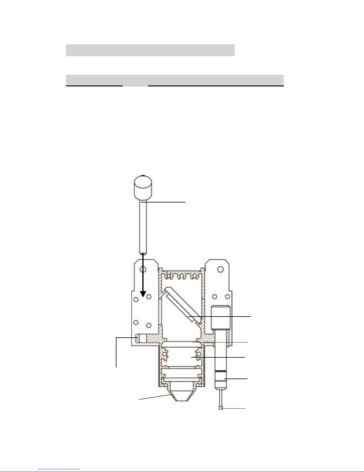
LENS and MANUAL FOCUS GAUGE
Focal Length Matched Color
LENS MANUAL FOCUS GAUGE
1.5” Standard Purple Blue (same as 2.0”)
2.0” Option Blue Blue
2.5” Option Gold Gold
Manual Focus
Gauge Holder
Insert to the hole
of the holder for
manual focusing
Mirror
Lens 2.0, 2.5
Slot position for
Lens 1.5 only
Auto Focus Gauge
Focal-Sharp™
Manual Focus Gauge
Figure of Focus Carriage
Focus Probe
NOZZLE
Page 7

7
I. INTRODUCTION
Principles of CO
2
Laser
LASER
is a Light Amplification by Stimulated Emission of Radiation.
A CO2 laser works by exciting the molecules of a carbon dioxide gas mixture.
To engrave, the beam is focused through a lens. The intensive beam can vaporize
the surface of the material leaving an engraved image or, in some cases, cutting
through the material.
Safety
The safety rating of Class 1 by CDRH means that the laser beam is enclosed in a
cabinet and has safety interlock mechanisms to protect the operator from
injury. While when a class 1 laser system equipped with a red dot pointer which
allows you to position laser beam, the safety rating turns into Class 3a due to the red
beam is laser light. A few extra safety precautions; namely, avoid placing your eyes
in the red beam path, is required.
!
Precaution
1. Do not attempt to modify or disassemble the laser system at any time.
2. Wear appropriate safety goggles especially when engraving with mirrors
or coated metals such as enameled brass and anodized aluminum..
3. Good ventilation is required to remove odors and vaporized materials to the
outside of the building or structure. An exhausted system is recommended.
4. Invisible intensive laser radiation may cause physical burns or sever eye
damage. Always read the manual and caution labels carefully before operation.
5. Do not work with reflective metals, heat sensitive surfaces or other materials
that may produce toxic substances, such as PVC and Teflon.
6. A fire extinguisher should be available on hand at any time.
7. Never leave the machine unattended during operation.
8. Follow the recommendations for maintaining and cleaning your system. Not
only will this enable you to engrave efficiently, it will ensure that your
machine runs safely as well.
Page 8

8
Fire Precaution
1.When engraving at 3D mode or cutting materials that easily caught on fire,
such as acrylic, wood or paper, it is advised to have air compressor turned
on to prevent flame.
2.If cutting table, or honey comb table, is used for cutting purpose, do not leave
any material underneath, as when material at top is cut through, the material at
below will be burned easily due to trapped heat.
3.It is not encouraged leaving the cutting job unattended, especially with
materials mentioned above.
Page 9
9
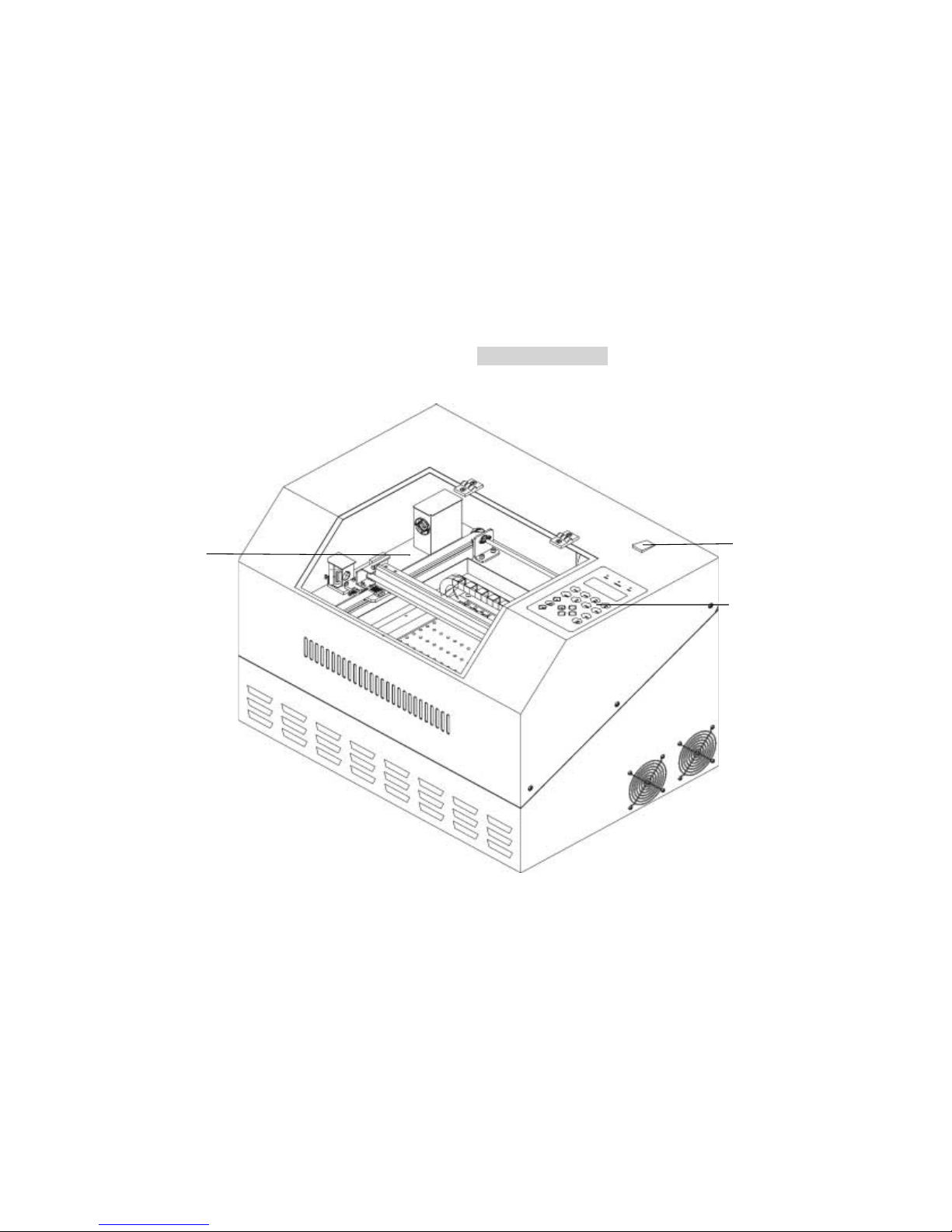
Fig. 1 Front View
Control Panel
Top Door
Power on/ off Switch
Page 10
10
Disassemble
to maintain
#1 mirror.
Please refer to the
right layout.
Laser
source
inside
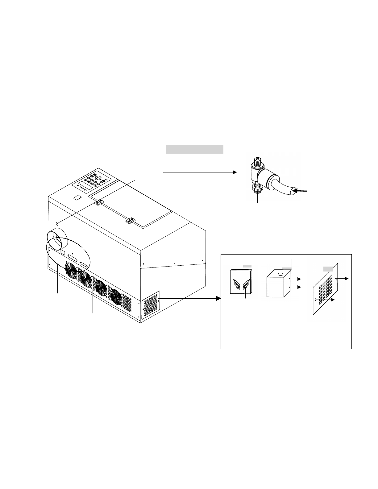
Fig. 2 Back View
Unscrew and
remove the
panel.
Unscrew and
remove the
dust prevention
box.
Unscrew and
pull out
#1 mirror
carefully
without
touching the
surface of the
mirror.
VIII.
VII.
VI.
NOTE: Please refer to Fig. 21&22 and follow the
instruction for the basic maintenance of mirror.
fuse &
Ports
Air inlet
connect to air
compressor
Turn clockwise to
decrease the air flow
and counterclockwise to
increase the air flow.
Press the ring to
pull out the air
tube.
Air Flow
Fixer
Air Flow
Adjuster
Page 11
11
-7-
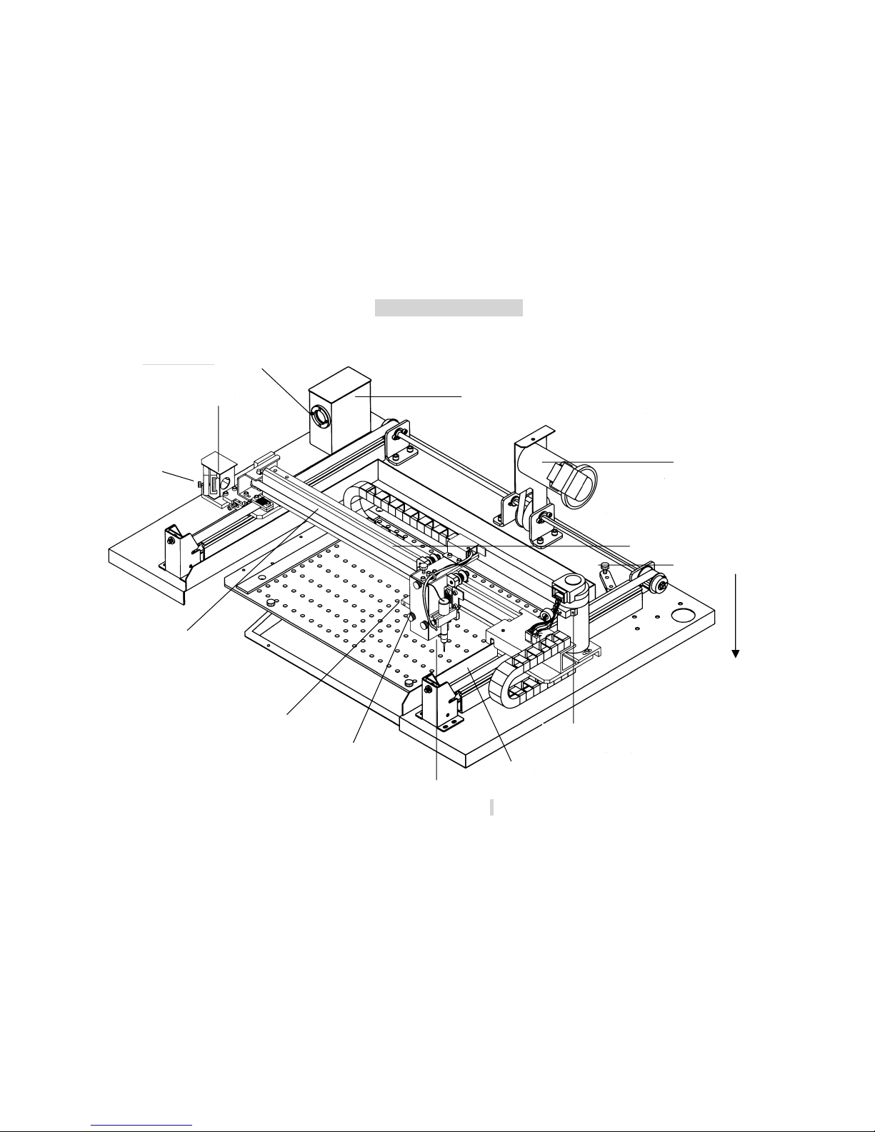
#4 Mirror Inside
Fig.3 Motion System I
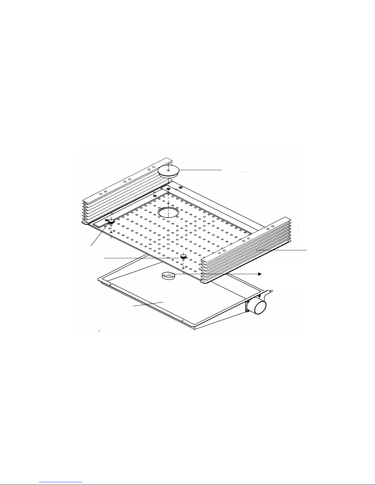
Choose air exhausting direction
either from back of the table or
through the holes on working
table. Adjuster in middle position
can exhaust air both backward
and downward.
I. Dust Prevention Box (#2 M irror
inside)
Y-axis
#3 Mirror & Holder
Release the Screw to
Pull Out the Mirror
Focal-Sharp™
II. Auto-focus
Manual Focus
Gauge Holder
X-axis
III. Y-axis
Motor
IV. Dust
Bearing Track
X-axis Motor
Air Flow Adjuster
#4 Mirror Inside
Page 12
12
Dust Collecting
Plate
Release the Screw to
Low down the plate
-8-
V. Hole
Dust Partition
Motion System II
The diameter of the object
in this circle must be less
than 45 mm
Page 13

13
II. RECOMMENDED CONFIGURATION
1.
Computer
:
Your PC must be sufficient to equip with Window 95 at least.
We recommend the specification of PC for better work as
below:
CPU Pentium at least
DRAM 32 MB RAM or up
FDD One 3.5" 1.44 MB floppy
HDD 1.2 GB Hard Drive or up
SVGA 15" Super VGA Monitor
★ ★On Board Parallel Mode(Setup from PC BIOS):
SPP—Preferred Mode
ECP—Cable length less than 1.8meters
2. Scanner
Flat Bed
Minimum resolution: 200 DPI
3. Software
GCC driver (designed under Window 95 or higher level)
Windows Window 95 or higher
CorelDRAW 7.0 Version or up
Any program that can output HPGL commands
Page 14

14
III. HARDWARE INSTALLATION
Caution:
! Turn all equipment off before making any
connection.
! Check the plug of the power cord to see if it matches the wall outlet. If not,
please contact your dealer.
Cabling Connection:
1. Insert the power cord (male) into a well grounded power outlet.
2. Plug the other end (female) into the engraver. The engraver has been designed to
switch from 100~240 VAC automatically.
3. The engraver can communicate with a computer through either a serial (RS-232C)
or a parallel port (Centronics).
Power on/off
Switch
15AMP resetable
fuse
Parallel Interface
Connector
3AMP resetable fuse
AC Power
Connector
Fig. 4
Serial Interface
Connector
Page 15
15
! Parallel Transmission
Connect a parallel cable to the engraver (parallel port) then to the parallel port
of the host computer.
Caution:
Never use a mechanical switch box when a second printer port is required.
The electrical surges can cause damage to the computer and the engraver.
! Serial Transmission
If you are using IBM PC, PS/2 or their compatibles, connect the supplied
RS-232C cable to the engraver (serial port) then to the serial port of the host
computer.
! Interface for Macintosh
To operate the engraver with a Macintosh computer (e.g. Power Mac), you
need a MAC modem cable (DIN8 to DB25) as an adaptor to connect to the
RS-232C cable.
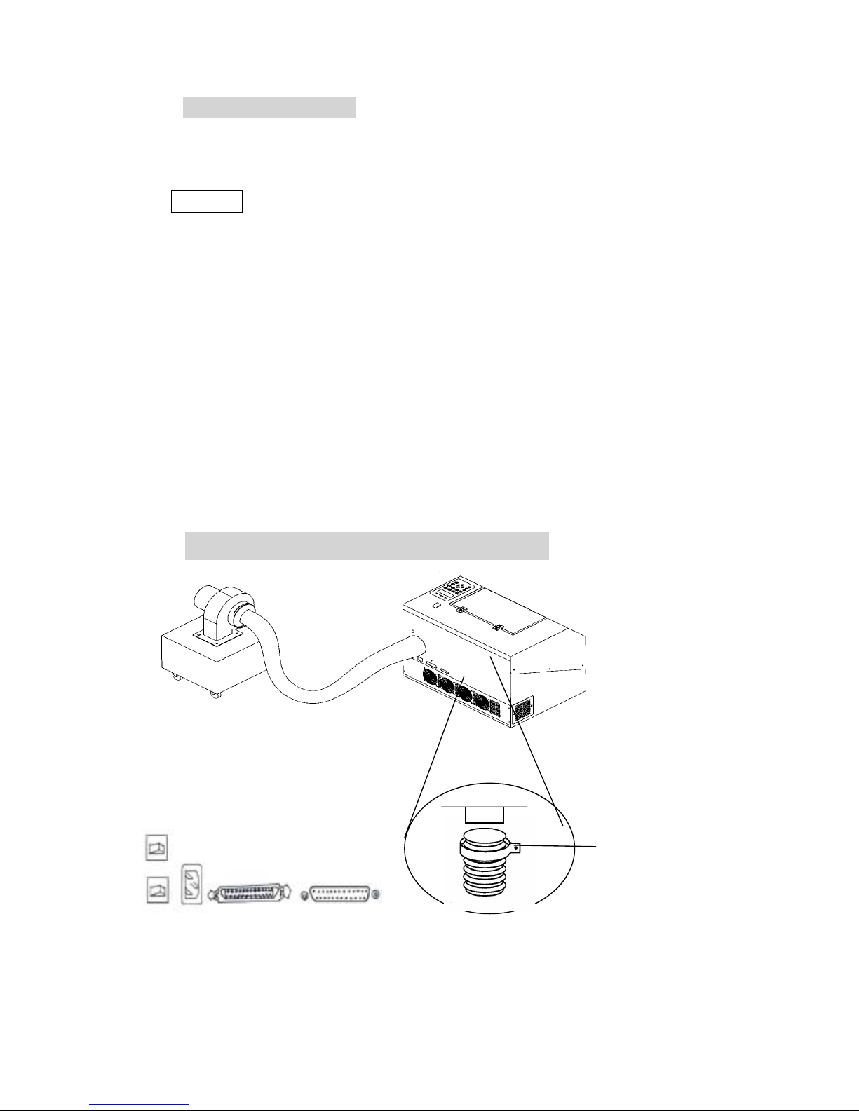
II. Exhaust Vent
2 or 4 inch
diameter
Fig. 5
Seal
Clip
Page 16
16
IV. SOFTWARE INSTALLATION
Install LaserPro VENUS printer driver for windows 95/98
Power On, click
START
→
→→
→ choose
Settings
and click
Printers
→
→→
→ Double click
Add printer
and start
Add printer wizard
→
→→
→
Next step
→
→→
→ Choose
Local
and click
Next step
→
→→
→ choose
Have disk
and click
Next step
→
→→
→ Insert the VENUS Driver disk properly into the floppy drive then click
OK
→
→→
→ choose the port where your laser system is connected and click
Next step
→
→→
→ name your system or bypass
→
→→
→ choose the driver to be default printer
→
→→
→
Next step
→
→→
→ select
No
when asked to print a test page and click
Finish
Now the LaserPro VENUS printer driver is installed completely. Don't forget to take
the GCC driver disk from the floppy drive and store in a safe place.
Page 17

17
V. OPERATION
Environment
! A clean, well-ventilated room with a temperature of 15℃~ 25℃ (60℉~78℉)
(Strongly suggested the temperature of 25℃) and a relative humidity between
30% and 40%, as an office type environment.
! Stable floor isolated from vibration.
! Avoid from unstable voltage supply.
! Short path for an effective air exhaust.
! Have a fire extinguisher available at any time.
Flexible Utility of Your Memory Buffer.
The standard memory buffer size of Venus is 16M and can be expanded to 64 M
(32M SIMM x 2). You can choose Multiple file mode with limited memory to save
files and re-call them for constant applications. Or, you can choose Single file mode
to get an unlimited data output while still keep files that you saved before under
multiple file conditions. However, the file sent under Single file mode will not be
saved. In other words, every time you want to engrave this file, you have to re-send
again from the host computer.
Page 18

18
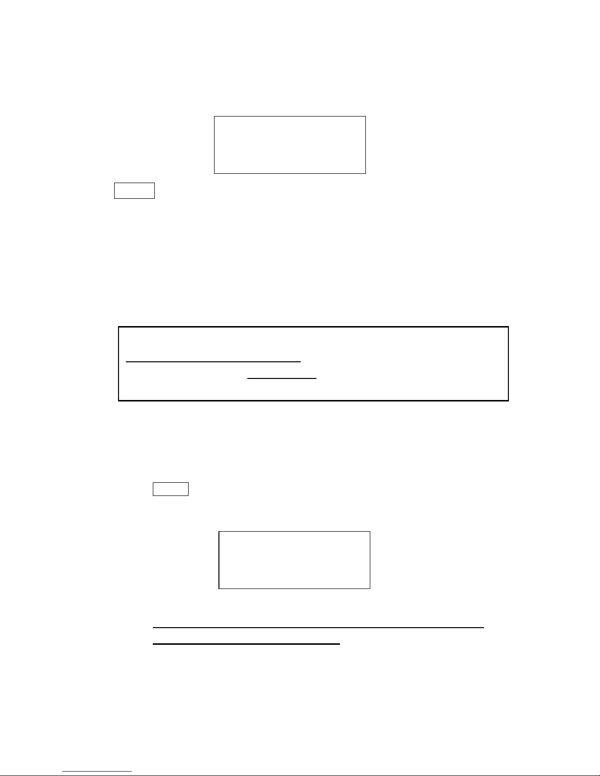
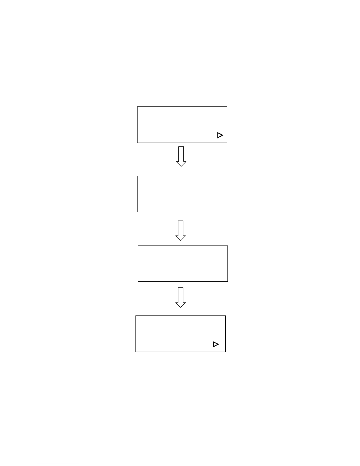
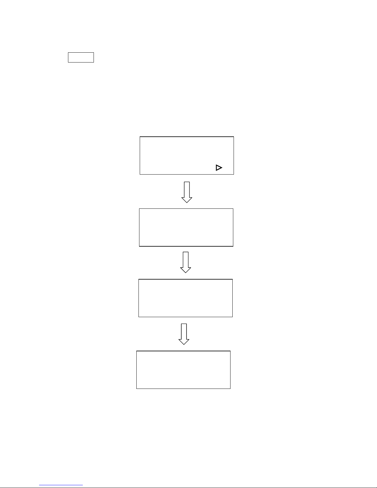
Am I in Multiple File mode or Single File mode now?
Power ON
NOTE: 1. ** means default or current setting.
2. AUTO FOCUS and all other function keys should be operated under
STOP condition.
3. NEXT FILE and DELETE keys are invalid under Single file mode.
Single /1 File
Ok: ENTER
Change: △△△△ or ▽▽▽▽
LaserPro VENUS
Firmware VX.X
Copyright 200X
Initializing
Please wait
Set memory buffer ?
Yes: ENTER
End operation: Esc
Z init/AF position?
Table moves down
about 50mm.
Press FUNCTION key.
Press ENTER key
Multiple /100 Files **
Ok: ENTER
Change: △△△△ or ▽▽▽▽
or
Page 19

19
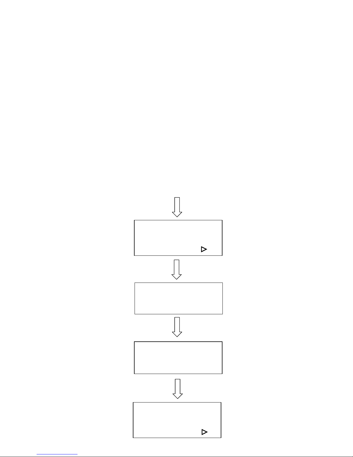
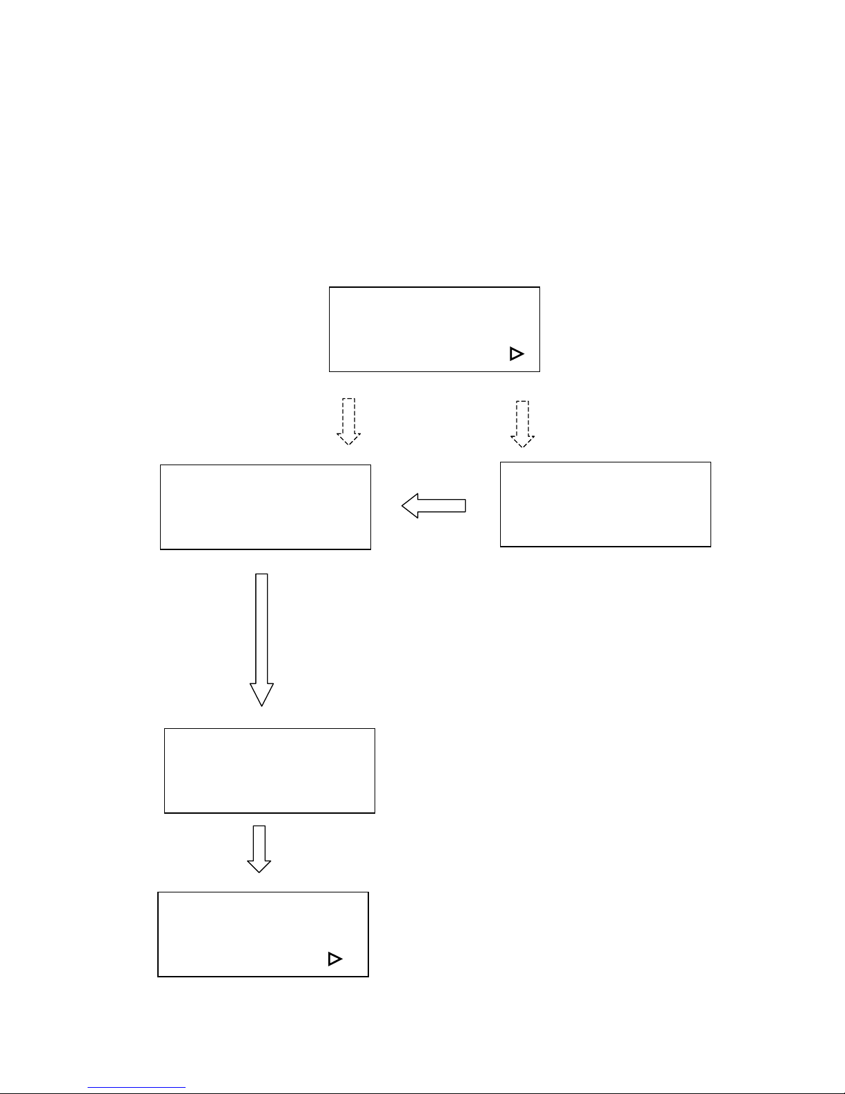
Start to Operate
Press
FUNCTION
key for further
setting
selection
Single file status
Under STARTcondition
Upon the receipt of files, start to
engrave/cut
LaserPro VENUS
Firmware VX.X
Copyright 200X
Initializing
Please wait
Table moves down about 50mm automatically
File:
Speed: %
Power: %
DPI:
File:
Speed: % 00:00
Power: % STOP
DPI:
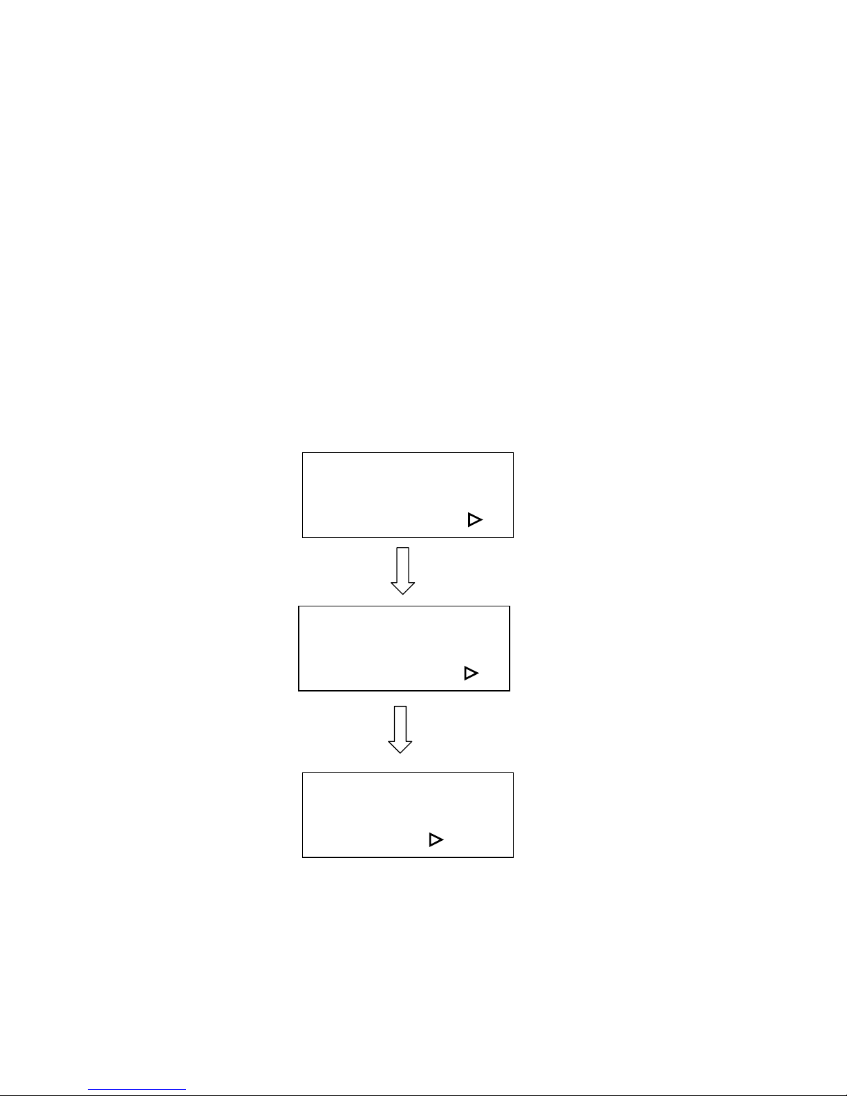
Multiple file status
Under STOP
condition
Press START/STOP,
turn to STOP condition
File: # x file name
Speed: xx.x % 00:00
Power: xx % PPI: xxxx
DPI: xxx xxx K
Send a new file
from host computer
then press
NEXT FILE
to show the file
name on LCD.
Press
NEXT FILE
to get a desired
file
Press
START/STOP
to engrave/cut
File: # x file name
Speed: xx.x % 00:00
Power: xx % PPI: xxxx
DPI: xxx xxx K
Power ON
Page 20
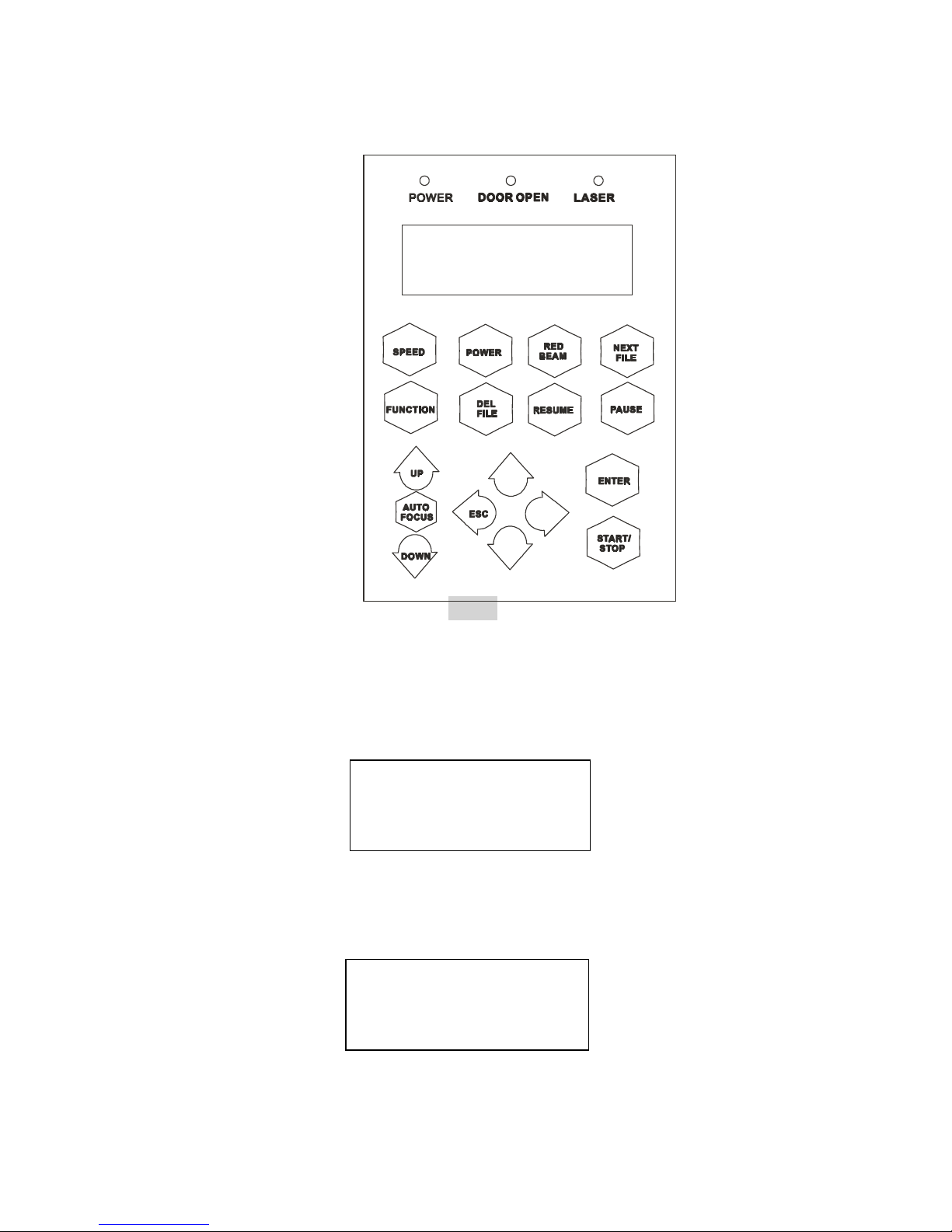
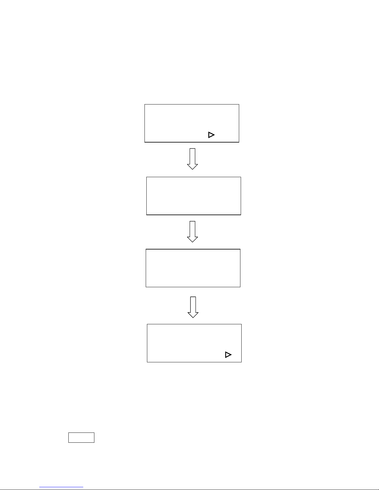
20
START/STOP
! Single File Mode:
Turn on power, VENUS is under START condition and ready to receive a file. LCD
shows as follows:
Upon the receipt of a file, VENUS starts to engrave/cut immediately. When a job is
done, LCD will show the working time such as 100s means 100 seconds.
Press START/STOP key, turn the engraver to STOP condition. LCD shows as
File:
Speed: %
Power: %
DPI:
File: file name
Speed: xx % 01:10
Power: xx % STOP
DPI: xxx
Control Panel
IX. Fig. 6
Page 21

21
follows. Under STOP condition AUTO FOCUS and all other function keys can be
operated while NEXT FILE and DELETE keys are invalid under Single file mode.
! Multiple File Mode:
Turn on power, LaserPro is under STOP condition and all function keys can be
operated. Laser engraver is ready to receive a file. LCD shows as follows.
Upon the receipt of a complete file, LCD will show the following message for
instance. Then press START/STOP key, the engraver start engraving or cutting.
If there is no file having been sent, the message will display as follows.
NOTE:
Please refer to the flow chart of “Start to Operate”, page 14 .
ENTER
Accept and store the selection for setting up.
AUTO FOCUS
This key can only be operated under STOP condition. Press this key will move up
the working table until the engraving object touches the tip of the focus tool, then
the table will move down and stop in focus automatically.
Whenever you change a lens with different focal length, press Function key and go
File: file name
Speed: % 00:00
Power: % STOP
DPI:
File:
Speed: % 00:00
Power: % STOP
DPI:
File: # 1 file name
Speed: 70 % 00:00
Power: 40 % STOP
DPI: 500
Wait until at least one
complete file is
Received, then press START
to start a job
Page 22
22
through the process of “Select lens” (refer to page 23). After changing the lens,
press AUTO FOCUS key to save the new focal length in memory. LCD will show
as follows:
NOTE:
1. “0.0 mm” means the focus position is the Z-axis home position of the
Working table. Above this position the value is negative while below
this position the value is positive.
2.Whenever the motion system or working table has ever been adjusted
by
a technical person, please press AUTO FOCUS key to get an initial
position before going through the function of “Tune (Auto focusing)” to
change the focal length.
Arrow Keys
Move cursor on the display for selection or adjust the working table on Z position by
pressing the arrow keys of UP and DOWN.
NOTE:
UP key – After initializing, press this key will move up the table. LCD
displays:
During working time (i.e. Start condition), this message won’t be shown.
When Auto Focus is under process, press UP key will stop the motion of
Auto Focus and change to up movement.
DOWN key – Same as above function but the motion direction is
opposite.
Focusing
Then do setup or send a file
to start a job
0.0 mm
Focusing
Then do setup or send a file
to start a job
-
X.X mm
NOTICE:
To stop the motion of auto focus, please press either UP or DOWN arrow
key. If you press the key continuously, working table will move up or down
correspondingly.
Page 23

23
ESC (Escape)
Exit and back to the main menu.
NEXT FILE
This key is valid under Multiple file mode only. Press this key the LCD shows
The “k” message shows on the lower right corner expresses the k bytes memory that
has been left over in the buffer.
File: # shows the current working file number. Press NEXT FILE each time will
increase 1 (i.e. 1, 2, 3…100) and recycle the counting. Once the buffer has received
up to 100 files, the LCD shows:
If a file received is out of memory, the LCD shows
RED BEAM
On/Off red beam
SPEED
Set up laser speed for desired effect. When working without using VENUS’s driver.
Press FUNCTION key then select one of the sixteen setups then set up desired
cutting speed. No matter you are using VENUS’s driver or not, you can press
PAUSE key prior to change speed during cutting or engraving. Set up desired speed,
press ENTER then press RESUME to start the job again.
POWER
Set up laser power for desired depth and effect. Other conditions are same as stated
in SPEED.
File: # x file name
Speed: xx % 00:00
Power: xx % PPI: xxxx
DPI: xxx xxxxx k
More than 100 files
are not allowed
Please delete some
and send again
Not a complete file
due to out of memory
Please delete some
and send again
Page 24

24
PAUSE
Temporarily stop the job during cutting or engraving.
RESUME
Restart the job after pausing.
DEL FILE
This key (delete file) is valid under Multiple file mode only.
Press DEL FILE again to delete the file and LCD shows
Delete current file?
Sure: Press again
No: Esc
Now deleting current
file Please wait
Page 25
25
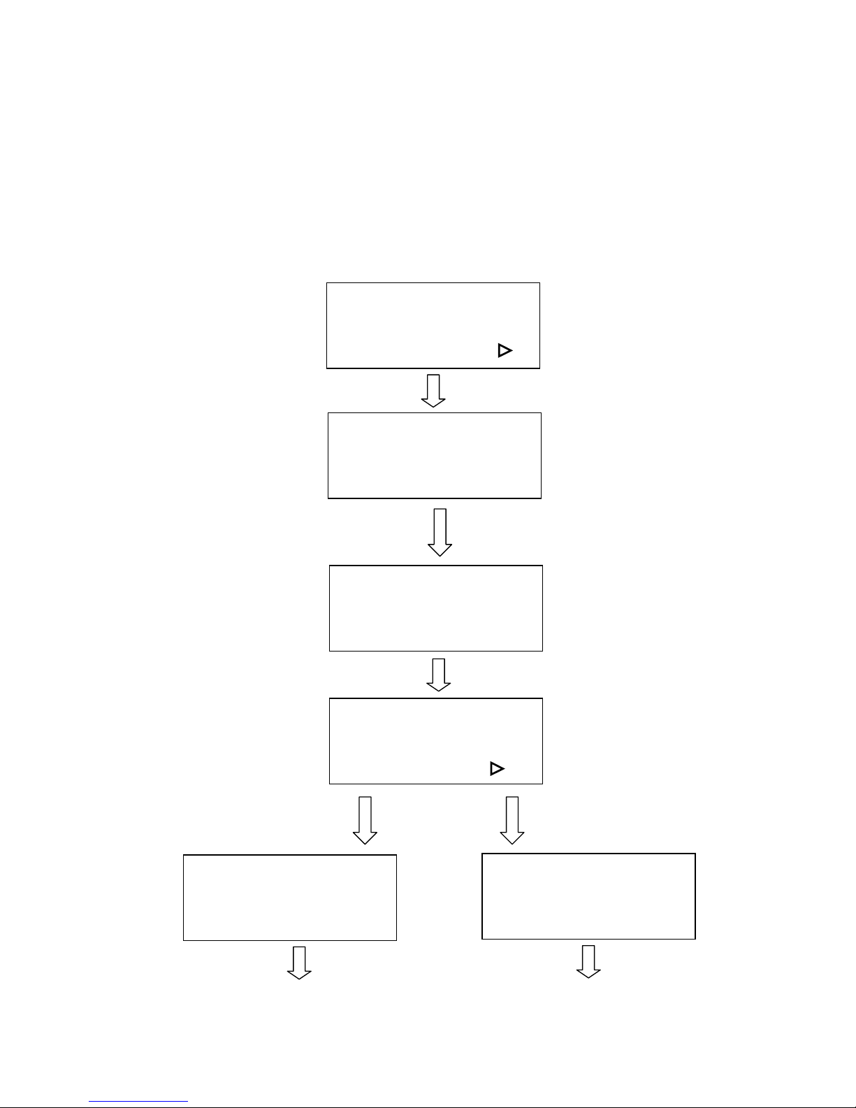
FUNCTION
! Set memory buffer?
Setting memory buffer in Single file mode when working with a large data file, or
Multiple file mode (up to 100 files) that can be saved for constant engraving.
Under Single file mode, you can only output one job a time. Unlimited data can be
transferred without saving in the buffer therefore once you want to repeat the job
you have to re-send the file from the host computer.
Under Multiple file mode, you can engrave one job while transfer and design the
next simultaneously until 100 files’ memories are all used up.
Press FUNCTION key
Single /1File
Ok: ENTER
Change: △△△△ or ▽▽▽▽
Set memory buffer ?
Yes: ENTER
End operation: Esc
Z init/AF position? :
Press ENTER key
Multiple /100 Files **
Ok: ENTER
Change: △△△△ or ▽▽▽▽
Z init/AF position?
Yes: ENTER
End operation: Esc
Delete all files ?:
ENTER
△
△△
△ or ▽
▽▽
▽
Page 26
26
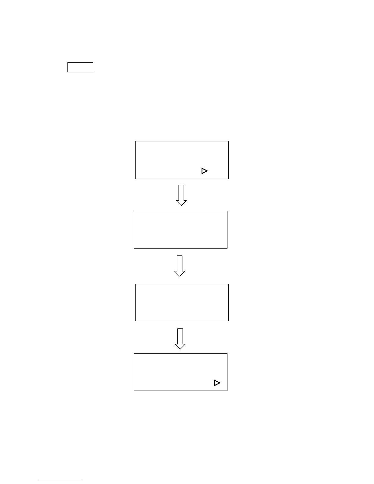
! Z init/AF position?
To avoid focus carriage hitting the engraving object accidentally during initializing,
working table will move down about 50mm automatically after power on the
equipment. Whereas, if a rotary attachment has been installed, the working table will
move down to the bottom of the engraver.
As long as you have not press AUTO FOCUS key, you can go into this function and
move the working table back to the original position before initializing. Once the
AUTO FOCUS key has been used, the last auto focus position has been saved in the
memory. Therefore, you can move the table to the last auto focus position instead of
the original Z position by using this function.
Z init/AF position?
Yes: ENTER
End operation: Esc
Delete all files? :
Table is moving to
init or AF position
End operation: Esc
Delete all files? :
Delete all files?
Ok: ENTER
End operation: Esc
Select lens? :
ENTER
Page 27

27
! Delete all files?
All files in the buffer will be deleted by using this function when setting under
Multiple file mode.
This function is invalid under Single file mode. Once you stop or complete a job
under Single File mode the file won’t be saved in the buffer.
Delete all files?
Ok: ENTER
End operation: Esc
Select lens? :
Are you sure?
Sure: ENTER
No: Esc
Select lens?
Yes: ENTER
End operation: Esc
Select unit? :
ENTER
ENTER
Page 28

28
! Select lens?
There are four different lenses for use on the LaserPro VENUS as follows:
Focal Length Resolution Cutting capability
1.5” standard
2.0” optional
2.5” optional
High
Low
Thin
Thick
The longer the focal length, the bigger the beam spot size. The high resolution lens
is designed for precision engraving, while the low resolution lens is mostly applied
for cutting due to its lower beam divergence which results in a straighter cut in thick
materials. However, using higher resolution takes longer time for engraving.
The large spot size of low resolution lens can spreads the laser’s heat over a larger
area, which helps minimize melting thus can be applied to engrave certain kinds of
plastics.
Select lens?
Yes: ENTER
End operation: Esc
Select unit? :
1.5 inch (38.1mm)**
Ok: ENTER
Change: △△△△ or ▽▽▽▽
△
△△
△ or ▽
▽▽
▽
x.x inch (xx.xmm)**
Ok: ENTER
Change: △△△△ or ▽▽▽▽
After changing lens, press
AUTO FOCUS and the
new focal length will be
saved automatically.
Select unit?
Yes: ENTER
End operation: Esc
Set EOF alarm? :
ENTER
Replace lens of
2.0 inch
2.5 inch
Page 29

29
! Set power ramp?
If set in Enable condition and cutting speed is 3% or above, under vector mode, the
power control is enabled. If set in Disable, the power control is disabled.
Default : Enable
Select unit?
Yes: ENTER
End operation: ESC
Set EOF alarm? :
Set power ramp?
Yes: ENTER
End operation: ESC
Select unit? :
ENTER
Enable **
Ok: ENTER
Change: △△△△ or ▽▽▽▽
Change: △△△△ or ▽▽▽▽
Disable
Ok: ENTER
Change: △△△△ or ▽▽▽▽
ENTER
Page 30
30
! Select unit?
Set unit in Metric or English.
NOTE:
** means default or current setting.
Set EOF alarm?
Ok: ENTER
End Operation: Esc
Tune (Auto focusing)? :
Select unit?
Yes: ENTER
End operation: Esc
Set EOF alarm? :
ENTER
Metric (mm)**
Ok: ENTER
Change: △△△△ or ▽▽▽▽
△
△△
△ or ▽▽▽▽
English (inch)
Ok: ENTER
Change: △△△△ or ▽▽▽▽
ENTER
Page 31
31
! Set EOF alarm?
If set in Enable condition, a beep tone sounds when End OF File.
Set EOF alarm?
Ok: ENTER
End operation: Esc
Tune Auto focusing? :
ENTER
Enable**
Ok: ENTER
Change: △△△△ or ▽▽▽▽
Disable
Ok: ENTER
Change: △△△△ or ▽▽▽▽
Change: △△△△ or ▽
▽▽
▽
Tune (Auto focusing)?
Ok: ENTER
End operation: Esc
Select set up #1-16? :
ENTER
Page 32
32
! Tune (Auto focusing)?
In case the focal length of Auto Focus needs to be corrected, please insert the
corresponding manual focal tool to the hole of the holder shown as in the Figure of
LENS and MANUAL FOCUS GAUGE. Then, operate as follows.
Press arrow up/down key
to tune focusing position
then press ENTER
ENTER
Tune (Auto focusing)?
Ok: ENTER
End operation: Esc
Select set up #1-16? :
Press AUTO FOCUS key
then FUNCTION key
Select the function
Tune (Auto focusing)
If you have not pressed
AUTO FOCUS after
power ON
If you have ever
pressed AUTO FOCUS
after power ON
A
ttach manual focus gauge to
the carriage and press arrow
key up and down to position
the working table in focus then
press ENTER.
New focal length has been
saved.
Complete tuning
Ready to setup or
send a file to
start a job
Select set up #1-16?
Yes: ENTER
End operation: Esc
Select baud rate? :
Page 33
33
! Select Set Up #1-16?
You can assign 16 different colors individually for speed and power to achieve a
variety of cutting effects. This function works when your software package can
output HPGL plot without using VENUS’s driver.
Press POWER key to change
Press SPEED key to
Power change speed
Setup # 1 **
+
++
+: △△△△ ----: ▽▽▽▽
Ok: ENTER
End operation: ESC
Select setup #1-16?
Yes: ENTER
End operation: ESC
Select baud rate? :
Change: △△△△ or ▽
▽▽
▽
ENTER
Setup # x
+:
+:+:
+: △△△△ -:
-:-:
-: ▽▽▽▽
Ok: ENTER
End operation: ESC
Select baud rate?
Yes: ENTER
End operation: ESC
Data bit/parity? :
ENTER
POWER: x x x %
+:
+:+:
+: △△△△ -:
-:-:
-: ▽▽▽▽
End operation: ESC
SPEED: x x . x %
+:
+:+:
+: △△△△ -:
-:-:
-: ▽▽▽▽
End operation: ESC
ENTER
ENTER
Save the desired cutting power
for not using Venus’s driver
Save the desired cutting speed
for not using Venus’s driver
Page 34
34
NOTE:
** means default or current setting.
! Select baud rate?
Baud rate is to determine the speed of data transmission to communicate with the
host computer.
Setting range: 9600, 19200, 38400, 57600, 115200
Defaults: 57600
57600 bps **
Ok: ENTER
Change: △△△△ or ▽▽▽▽
Select baud rate?
Yes: ENTER
End operation: Esc
Data bit/parity? :
ENTER
xxxxxx bps
Ok: ENTER
Change: △△△△ or ▽▽▽▽
Set data bit/parity?
Ok: ENTER
End operation: Esc
Select language? :
ENTER
△
△△
△ or ▽
▽▽
▽
Page 35
35
NOTE:
** means default or current setting.
! Set data bit/parity?
Data bits refer to the size of one block of data and parity is used to check if data
was received correctly or not. The data/parity feature is to adjust the byte format
and parity type in order to communicate with the host computer.
8 bits no parity **
Ok: ENTER
Change: △△△△ or ▽▽▽▽
8 bits even parity
Ok: ENTER
Change: △△△△ or ▽▽▽▽
Set data bit/parity?
Ok: ENTER
End operation: Esc
Select language? :
△
△△
△ or ▽
▽▽
▽
ENTER
Select language?
Yes: ENTER
End operation: Esc
ENTER
Page 36

36
Page 37

37
! Enable/Disable auto focus
The manufactures’ default is Auto-focus enable. If auto-focus set as disable, the
working table will not lower down automatically as soon as power turned on.
Set data bit/parity?
Yes: ENTER
End operation: ESC
Set autofocusing? :
Set autofocusing?
Yes: ENTER
End operation: Esc
Select language ? :
ENTER
Enable **
Ok: ENTER
Change: △△△△ or ▽▽▽▽
Disable
Ok: ENTER
Change: △△△△ or ▽
▽▽
▽
△
△△
△ or ▽▽▽▽
Page 38

38
! Select language?
NOTE:
** means default or current setting.
Select language?
Yes: ENTER
End operation: ESC
English **
Ok: ENTER
Change: △△△△ or ▽▽▽▽
ENTER
△
△△
△ or ▽
▽▽
▽
xxxxxx
Ok: ENTER
Change: △△△△ or ▽▽▽▽
Do setup or send at
least one file then
NEXT FILE key select
a file then START
Do setup or press
STAR key then
send only one file
Single file mode
ENTER or ESC
Multi file mode
Page 39

39
Software Operation
After completing your editing job choose File Print, click “Properties”
(refer to Fig. 7)
Fig. 7
Options:
(refer to Fig. 8)
Fig. 8
Page 40

40
Mode:
! Black & White mode
Let you obtain half-tone effect quickly without going through complex steps
of application (operating procedures shown as :a) Editing file, and b)
Engraving, on the following paragraph) softwares to obtain the similar effect.
You can choose the look of the laser engraved photo by applying one of the
driver software’s halftone options: Fine, Coarse or Error Diffusion.
#
Fine
Apply a 17-grade-half-tone with 4x4 dots pattern, consists of a small and
closely spaced dots.
#
Coarse
Apply a 65-grade-half-tone with 8x8 dots pattern, consists of larger, more
prominent dots. Represent a better contrast effect but result in a lower
resolution than Fine Mode of 4x4.
#
Error Diffusion
This is not really a halftone pattern but to manipulate the fill pattern in a
photograph ( a TIF image) through a series of random black and white pixels
that represent shading. The random pixel pattern tends to result in an image
that has more contrast and is more realistic looking.
#
Contrast
Enhance the grayscale level to get a better image contrast result in a good
engraving image (refer to Fig.9).
#
Pattern Type
The Fine or Coarse halftone pattern has three kinds of layout options.
Dot (default setting)- A halftone pattern consists of dots.
Corner- The dark dot spread from the left upper corner of the pattern result
in a little triangle shape to imitate a shading effect.
Random- A random halftone pattern.
NOTE:
Black & White mode is the easiest way to get the half-tone effect.
However if a higher image quality is required, please refer to the
following steps operated by CorelDRAW V. 8.0.
a) Editing file:
Layout Page Setup Set from Printer, Landscape
OK Edit desired file (picture etc.) Bitmap Transfer to
Bitmap, 256 shades of gray chose proper DPI OK
Bitmap Convert to Black and White, choose error
diffusion OK
Page 41

41
b) Engraving (Printout):
File Print Properties, choose Options and the default
mode is set up at Manual color fill then set up proper resolution, power
and speed OK
NOTE:
Please refer to “NOTICE” of Quick Menu in the front page.
4. Fine 5. Contrast 10 6. Dot
7. Coarse
Contrast 50
8. Corner
9. Error Diffusion 10. Contrast 80 11. Random
Fig. 9
Page 42
42
3D Image File
12. Sample/ Material: Density
Board
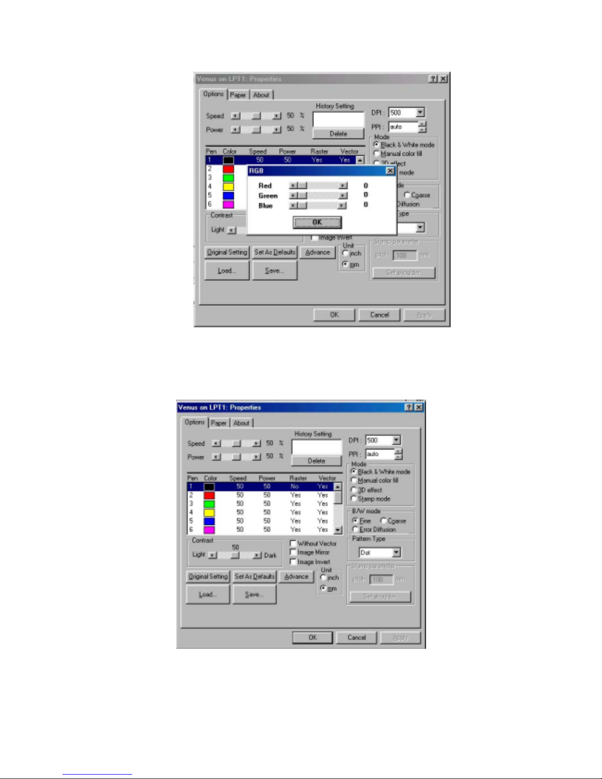
! Manual color fill
Each power and speed setting can be linked to certain color on the layout.
Totally 16 color settings are available. The desired color can be adjusted
by changing the ratio of Red, Green and Blue (refer to Fig.8). If the speed
or power is set to 0, the corresponding color area or vector line will be
invalid.
! 3D effect
With this function, we can get the sculpture effect. The engrave image must
have gray levels (refer to Fig.10). The engrave image is effected by PPI, DPI,
power and speed setting.
! Stamp Mode
Mainly used in rubber stamp production. Create a slope base of stamp
characters by setting up the stamp parameter (refer to Fig. 11). Normally
the pitch number for engraving a 2~3mm thick rubber pad can be set at 0.2 or
0.3. The smaller the pitch number, the sharper the slope. If setting the pitch
number at a very big value, it may take for a very long time for the math
calculation.
Fig. 10
Page 43

43
Fig. 11
For example, to engrave stamps with L-25 (25Watt), depends on the
thickness of the rubber pad. 2~3mm rubber pad for instance, the ideal power
is 100% at speed around 7%. The pitch value varies depending on the size of
text; the bigger the letter is, the bigger the pitch value is required. With 1cm
size letter, for example, 0.1~0.3 pitch value is enough. It is hard to tell
exactly which model of LaserPro most suitable for making stamps. Of course
the higher the laser power is, the less time it takes to do the same job. It
really needs to see what thickness of the rubber you will engrave on and the
letter size you use for most applications. The bigger the pitch value is, the
longer time computer will take to process.
#
Image Invert
Reverse the black and white image. Remain the characters but engraving the
rest areas of rubber stamps. This function is disable under the Manual color
fill mode.
#
Image Mirror
Reverse the left and right side as a mirror image.
#
Without Vector
Output without vector data.
#
Power Level of Stamp Mode
This function is to adjust the power distribution of the slope shoulder to get
the better shape of stamp’s vertical profile. Select “set shoulder” in the page
Page 44
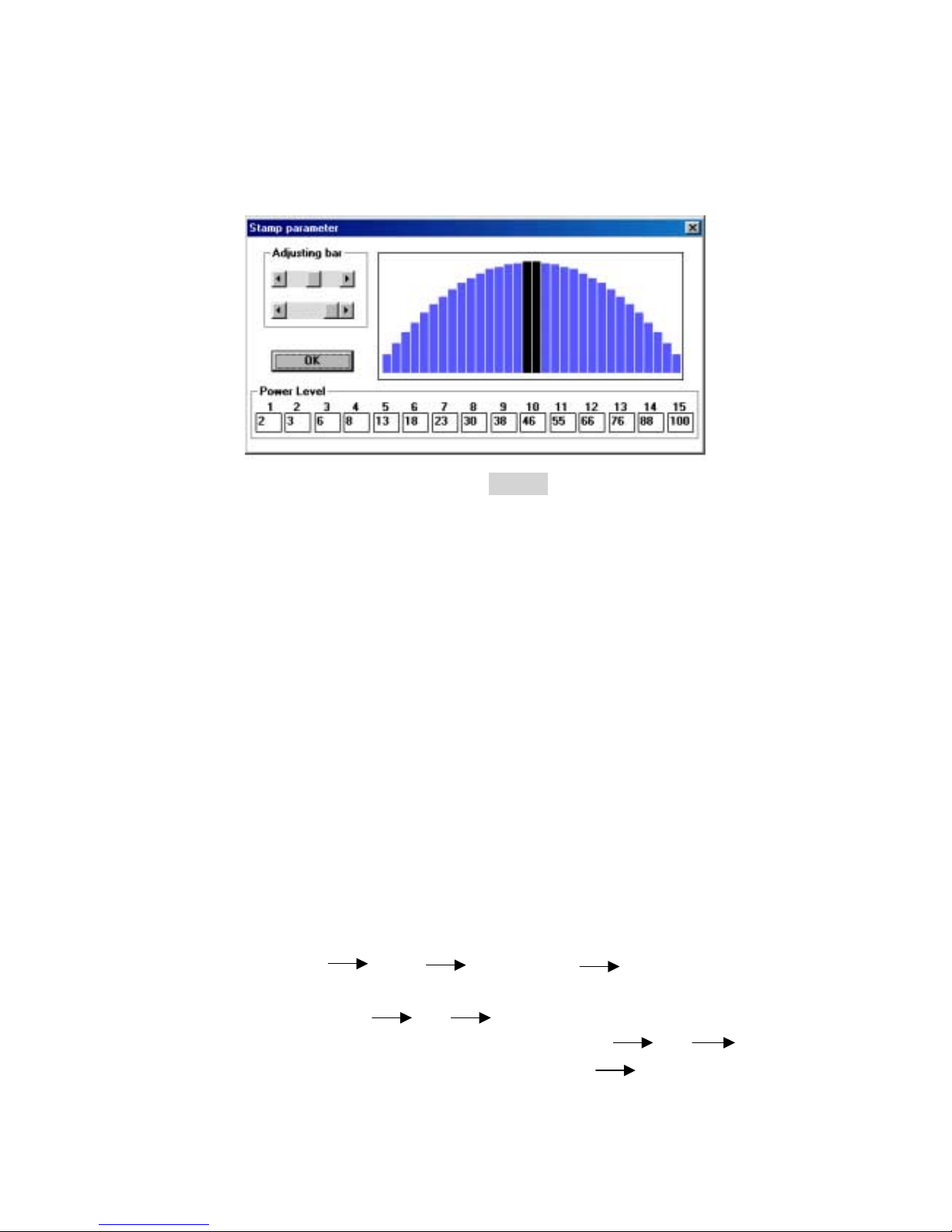
44
“Options”. Enter the dialog box of stamp parameter. The black bars in the
center are for the surface of each letter, while the blue bars are for the
shoulders. Adjust the value of power level by adjusting bar or the left click of
mouse to edit the shape of the shoulders (refer to Fig. 12).
! P.P.I.
P.P.I. stands for the laser firing pulse per inch.
$ Purpose: By changing the laser firing pulses per inch, the distribution of
energy would be changed.
#
Description: The adjusted range is 30 to 1500 PPI or you can choose auto
mode. When choosing auto mode, the system will come up with the proper
PPI value automatically. In order to maintain the quality of raster graph, the
PPI value will at least equal to DPI value automatically even you set the
lower PPI value than DPI value.
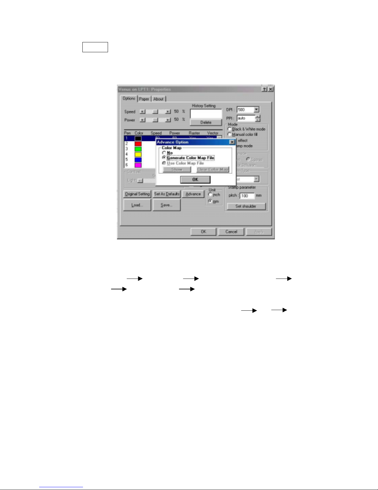
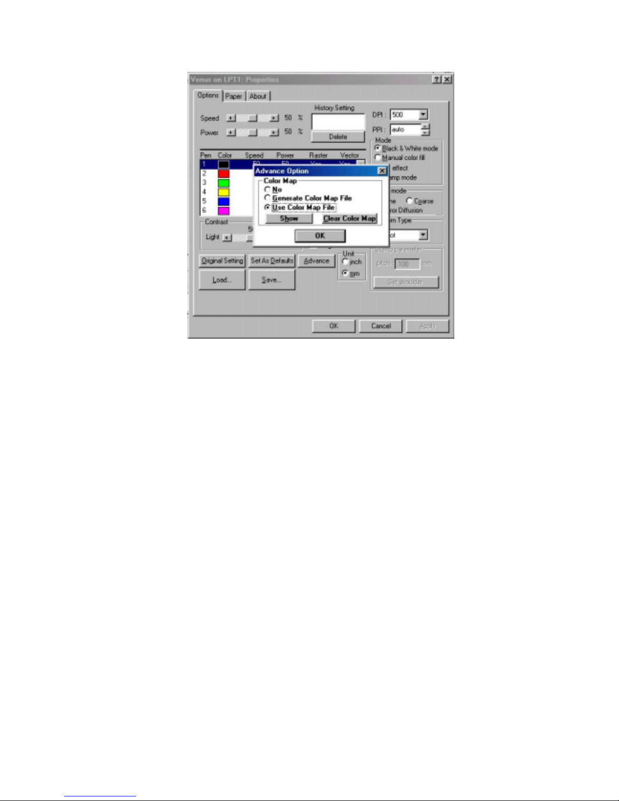
! Advance (Color Map)
Apply this function to detect if the power and speed settings linked to the right
color used in your layout. Thus, some areas can be engraved deeper than others
for desired effects. These settings can be saved for future use. The Advance
function can map vector data for all four types of modes. While the raster layout
(except bitmap files) can only be applied with the Manual color fill.
Operation: Two steps to complete the process.
Step 1: Edit file Print Properties Click Advance
Select Generate Color Map File (refer to Fig.13) on the Advance
Option dialog OK click Print, dialog shows “Generate
Color Map?” choose Yes then enter file name OK map
the desired parameters and colors accordingly Save
X. Fig. 12
Page 45
45
NOTE:
Step 1 is for saving data files only. You have to go to Step 2 to print
out the file.
Fig. 13
Step 2: To output data
Print Properties Load then enter file name OK
Click Advance Select Use Color Map File (refer to
Fig. 18). The power and speed are changeable as desired and you
can click Show to see the data of the color map. OK Print
Page 46
46
Fig. 14
! Original Setting
Recall the default value set by manufacturer.
! Set As Defaults
Save your constantly used parameters as a new default setting. Thus, whenever
you open a new file, the default setting will be adopted automatically.
! History Setting
Limited 10 constantly used files and parameters can be saved in the History
Setting. To recall, please double click the file name.
! Save
Clicking this button and give a file name to save your file or save the file into the
History Setting through the instruction of dialog.
! Load
Click this button to reload old file.
! To modify color
Double click the color box (refer to Fig. 15) to modify the color by adjusting the
RGB (Red, Green and Blue) ratio.
Page 47
47
Fig. 15
! Raster/Vector
Double click Yes/No to get the Raster/Vector output (Fig.16).
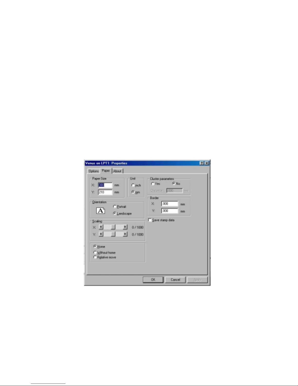
Paper
: (refer to Fig.17)
Fig. 16
Page 48
48
! Paper Size: Set up the working size for engraving.
! Scaling Function
Apply this function to adjust the difference in size between the object in the page
of software and the real object engraved. Scale can be adjusted up to ± 50/1000.
Positive value is to enlarge the size, negative to reduce. For examples, adjust the
scale by +10 to enlarge the object’s size by 10/1000.
! Position Mode:
#
Home: Focus carriage goes back to the upper right position after finishing a
job.
#
Without Home: Focus carriage stops at the last position of a data file.
#
Relative Move: You can place the focus carriage at any place you want to
start a job. When finishing a job, the focus carriage will move back to the
original starting point.
Fig.17
! Cluster
In order to reduce the working time, the output movement can be
clustered under stamp mode.
As for Fig.17, suppose the “Distance” you specified is D and the distance
between graph A & B is X (refer to Fig. 18). If you chose the function
“Cluster” and X > D, the output movement will be route b. If you don’t
chose “Cluster” or even you chose “Cluster” and X ≤ D, the output
Page 49
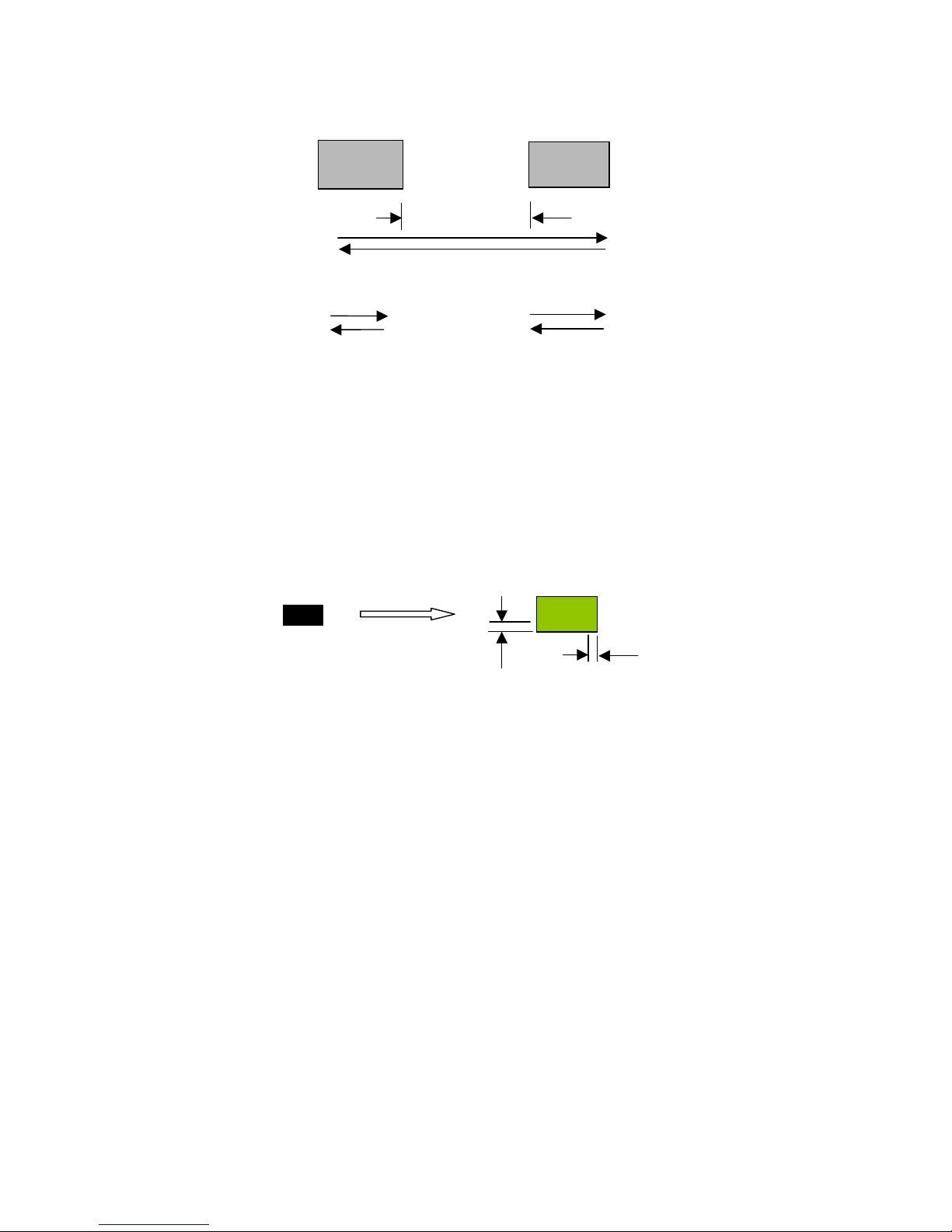
49
movement will be route a.
! Border
You can add border at image edge for a better output of the stamp image
(refer to Fig. 19).
You must select “Image Invert” (refer to Fig. 16) under stamp mode when
using border. As for Fig.17, you can specify the border X and Y. If you
chose the “Cluster” and want to have border, the border X and Y must be
less than the “Distance” D you specified.
origin
Add border
X
Y
Fig. 19
route a
route b
A
B
Fig. 18
X
Page 50

50
VI. BASIC MAINTENANCE
Caution:
! Keeping the optics and motion system clean is essential to an excellent quality
engraving and the reliability of your engraver. Please clean Bearing track and
X-axis (DU) bearing daily to maintain good condition of machine.
! Never pour or spray any liquid directly onto the laser system.
! Turn off the power and unplug the system before cleaning.
1.
Inside the System:
Open the top door, the front door and the back door (if
necessary). Vacuum to clean inside of the engraver and vent area thoroughly.
2.
Engraving Table:
Dampen the paper towel or cloth with alcohol or cleaner
to clean the Engraving Table.
3.
Motion System:
Dampen the cotton swab to clean the rails of the Motion
System. Get rid off any debris built up in the bearing tracks.
4.
Bearings:
Hold a dampened cotton swab against the bearing and moving the
motion system by hand to clean each bearing.
5.
Mirrors and Lenses:
The focus lens and the mirror located on the carriage
are
the two components most likely to require cleaning once a week.
Caution:
Don't scratch out the soft coating of the mirror's surface. Excessive cleaning
the mirrors and lenses may cause damage and reduce the life of the mirror
(refer to Fig. 21).
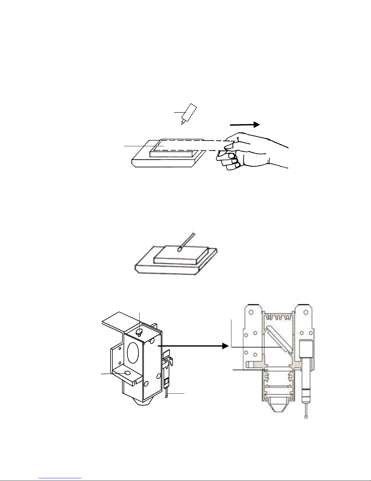
Clean the mirror -
1. Unscrew and remove front cover of the focus carriage. Release the
top screw and pull out mirror carefully (refer to Fig. 22).
2. Put lens tissue on the mirror and drop a little lens cleaner on the
middle area of the tissue (please refer to Fig. 20), after the fluid has
been absorbed evenly, pull the tissue
one direction
gently to
clean the mirror.
3. Let it air dry and re-install it.
4. Unscrew and remove the dust prevention box (refer to Fig. 2 & Fig.
3) then clean the #2 Mirror, #4 Mirror and #1 Mirror same as above
process (refer to Fig. 20) separately.
Page 51
51
╳╳╳╳ (INCORRECT)
(INCORRECT) (INCORRECT)
(INCORRECT)
Do not use cotton swab to
rub clean the mirror
○○○○ (CORRECT)
(CORRECT) (CORRECT)
(CORRECT)
Lens
Tissue
Pull the tissue one
direction gently after
the cleaner has been
absorbed evenly
Lens Cleaner
○○○○ (CORRECT)
(CORRECT) (CORRECT)
(CORRECT)
Remove
Front Cover
Mirror
Len
Loading hole
for manual
focal tool
Auto-focus
Fig. 22
Top Screw
Page 52

52
! Clean the focus lens –
1. Unscrew and remove the front cover of the focus carriage. Pull out
focus lens carefully (refer to Fig. 22).
2. Flood the focus lens with lens cleanser on both sides then using a
cotton swab or lens tissue to dry off the remaining solution gently.
3. Do not touch the lens surface with your bare hands or press down
hard with any cleaning material.
Page 53

53
VII. TROUBLE SHOOTING
Quality Problems
! Check focus length set under the function key to see if it matches the type of the
lens installed.
! Focus Lenses are not installed correctly. Focus Lens loose in the holder.
! Debris or dust builds up in the bearing tracks or X-Axis rails.
! The focus lens and the mirror in the carriage are damaged or need to be clean.
Non-operational Problems
! Laser beam does not generate.
1. If the red alignment beam is not revealed, the laser beam is misalignment.
Adjust reflection mirrors for exact focus.
2. If the red alignment beam is revealed, please check the driver power. The
laser power may be too low to be detected. Please increase the percentage
setting of
the Laser Power from the software driver or the control panel.
3. Please check if the laser power connector is loose.
4. For safety purpose, the laser beam will not be generated when the top or
front door is opened unless you short the connector of the magnetic switches.
Page 54

54
LaserPro Venus
VENUS V-12
Laser Source 12W
Sealed CO2 laser
Work Area 11.8"x8.3"
(300mm × 210mm)
Max. Working Piece (W×D×Thick) 14.2"x11.8"x2.8"
(360x300x70mm)
Table Size 14.2"x11.8"
(360x300mm)
Overall Dimensions 24.4”x17.1”x16.5”
W×D×H (620x435x420 mm)
Weight 32 Kg /70 lb
Drive DC servo control
Speed Control Adjustable from 0.02 to 20 inch/ se c with u p
to 16 colors linked speed setting per job
Power Control
Adjustable from 0〜〜〜〜100% and 16 colors
linked power setting per job
Z Axis Moving Automatic
Resolution (DPI) 1000, 600, 500, 300, 250, 200
Computer Interface Print port and serial port for PC
Memory Buffer 16MB standard upgradable to 64 MB with
SIMM modules. Multiple file mode saves up
to 100 files.
Display Panel 4-line LCD display showing current file
name, total working time. Laser power,
engraving speed, file loaded into memory
buffer, setup and diagnostic menus.
Power
100〜〜〜〜240V, AC Auto Switch
10Amp
Cooling Air-cooled
Above specification is subject to change without prior notice.
Optional Items: Odor Reduction System
Air Assist System
Appendix I. Specification
Page 55

55
Compressor for Air Assist System
Dust Prevention Window
Goggle
Page 56

56
Appendix II. 3D Function
Tip for 3D Application
When doing 3D sample on LaserPro Mercury (L-25), acrylic or MDF wood are
ideal materials for the purpose. For acrylic the suggested PWR is 100%, SPD around
30%(depends on how deep you want to cut).
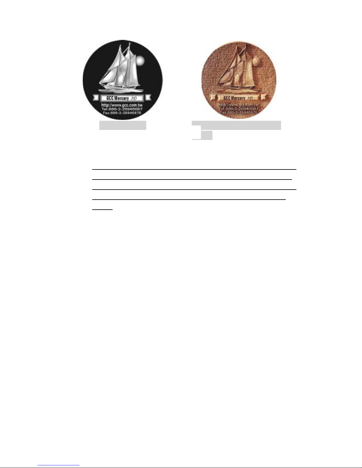
The perfect image for 3D is like those shown below. When image is ready,
choose 3D Effect as the output mode in the driver. Sometimes, some material
shows better effect if you run the job with 2nd pass with laser out-of-focus.
Especially with acrylic, the 2nd pass will smooth out the surface.
For engraving wood, as it burns easily and leaves blackened surface after the
1st pass, it is necessary to run the 2nd pass to remove the burned surface. To do
that, simply fill the image with black colour as the mask (see below) and Run the
black mask image with PWR 100% and SPD100%.
Create a black image
for polishing
Page 57

57
13. 3D engraving / Material: 1cm Acrylic by Mercury 25W
Lens: 2 inch
Step
Spee
d
Power DPI PPI
Focus
FocusFocus
Focus
Remarks
1
25% 100% 600 auto Auto Focus 3D Mode Engraving
2
25% 100% 600 auto Lower down table 2.5mm 3D Mode Engraving
3
100% 100% 600 800 Lower table again 2 mm Black and White Mode Polishing
4
0.2% 100% 500 auto Move table up 1.3mm Cutting off
14. 3D engraving / Material: 1cm Acrylic by Venus 12W
Lens: 1.5 inch
Step
Spee
d
Power DPI PPI
Focus
FocusFocus
Focus
Remarks
1
13% 100% 600 auto Auto Focus 3D Mode Engraving
2
13% 100% 600 auto Lower down table 2.5mm 3D Mode Engraving
3
100% 100% 600 800 Lower table again 2 mm Black and White Mode Polishing
4
0.1% 100% 500 auto Move table up 1.3mm Cutting off
Page 58

58
Page 59

59
 Loading...