

Page 1
Distributed & Supported by: Jorlink USA, Inc. | Tel: (336) 288-1613 | [email protected] | www.JORLINK.com
1/60
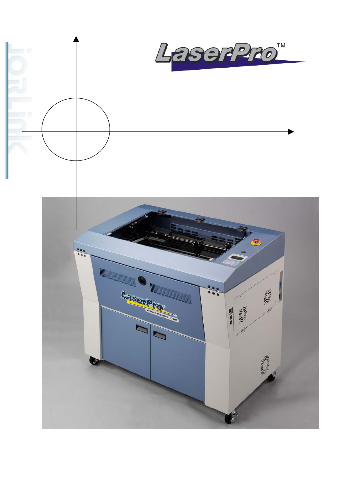
Maintenance Manual
Spirit SI /GE/GX/LS
Page 2

Spirit SI/GE/GX/LS Maintenance Manual
Distributed & Supported by: Jorlink USA, Inc. | Tel: (336) 288-1613 | [email protected] | www.JORLINK.com
2/60
Introduction.
Serial number.…...…………………………………………………………..3
Safety Precautions…………………………………………………………..3
Chapter 1. Machine Overview
Section 1. Mechanical System
- Overall…………………………………………………………………..4
- Top Cover……………………………………………………………….5
- Mid Section……………………………………………………………..6
- Base Section…………………………………………………………….7
- X-axis Assembly………………………………………………………..8
- Y-axis Assembly………………………………………………………...9
- Pen carriage……………………………………………………………10
- Z-platform……………………………………………………………..11
- Mirror 1 / Laser unit…………………………………………………...12
- Power Supply………………………………………………………….13
- Base section side panel………………………………………………...14
Section 2. Power System
- Power Supply...………………………………………………………..16
- Power cable layout diagrams…………………………………………..17
Section 3. Electrical System
- Mainboard……………………………………………………………..20
- DC 12V Module……………………………………………………….21
- Laser Power Adaptor…………………………………………………..21
- Control Panel…………………………………………………………..22
Section 4. Laser System
- Types of laser tube Deos/Synrad………………………………………23
- How to measure laser power?…………………………………………23
- Optical alignment……………………………………………………...24
- Laser tube wiring diagrams……………………………………………25
Section 5. Firmware
1
Page 3

How to upgrade Firmware?………………………………………………..31
Distributed & Supported by: Jorlink USA, Inc. | Tel: (336) 288-1613 | [email protected] | www.JORLINK.com
3/60
Chapter 2. System Diagnostics
Section 1. Hidden Diagnostics……………………………………………………….32
Chapter 3. Preventive Maintenance
Section 1. Cleaning Lenses…………………………………………………………..34
Section 2. Cleaning and protecting the X, Y rails……………………………………37
Section 3. Changing the X rollers……………………………………………………39
Section 4. Changing the X-rail……………………………………………………….30
Section 5. Changing the Y rollers…………………………………………………….43
Chapter 4. T rouble Shooting (Error messages)
Section 1. Error messages……………………………………………………………44
Section 2. Error lights………………………………………………………………..48
Revised 02, January, 2006
2
Page 4
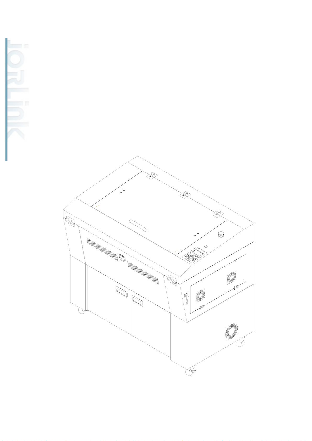
Introduction
Distributed & Supported by: Jorlink USA, Inc. | Tel: (336) 288-1613 | [email protected] | www.JORLINK.com
4/60
1. Serial Number.
The Serial number of your machine is very important and unique. Please copy down
the serial number and keep it for your records. Please include this serial number
when you correspond with us for any kind of questions. Thank you.
2. Safety Precautions.
The machine should not be operated without supervision. Due to the dangerous
nature of laser, we should always pay attention to what is going on with the machine.
DO NOT leave a running machine unattended.
3
Page 5
Chapter 1. Machine Overview
Distributed & Supported by: Jorlink USA, Inc. | Tel: (336) 288-1613 | [email protected] | www.JORLINK.com
5/60
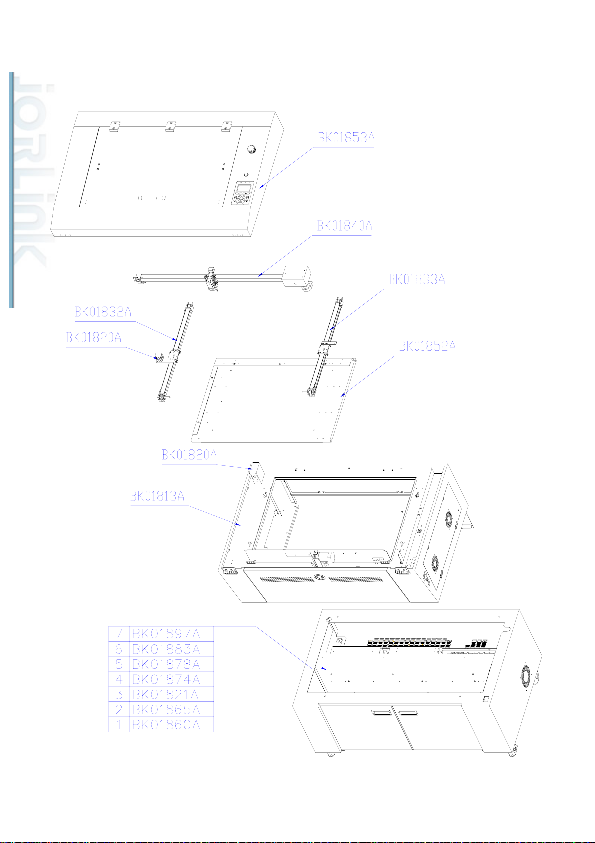
1. Overall
4
Page 6

Parts Number for
Distributed & Supported by: Jorlink USA, Inc. | Tel: (336) 288-1613 | [email protected] | www.JORLINK.com
6/60
Parts Number for
Parts Number for
Parts Number
Parts Name
SI
BK01853A 29003643G 29004573G
BK01840A 29003676(02) 29004575G
BK01832A 29002531 29004576G
BK01833A 29002532 29004577G
BK01852A 29003644(01) 29004574G
BK01813A 29003645(03) 29004578G
GE
GX
for LS
29006263G
29006040G
29005927G
29005928G
29002548G
29002516G
Top cover assembly
X-axis assembly
Y-axis assembly (Left)
Y-axis assembly (Right)
Working Table
Spirit unit chassis
BK01897A 29003969(02) 29004732G N/A 100W base chassis
assembly
BK01883A 29003893(02) 29004572G 60W base chassis
assembly
BK01878A N/A N/A N/A 50W base chassis
assembly
BK01874A N/A 29004733G 40W base chassis
assembly
BK01821A 29003894(02) 29004734G 30W base chassis
assembly
BK01865A N/A N/A
29004231G
25W base chassis
assembly
BK01860A N/A N/A 12W base chassis
assembly
5
Page 7
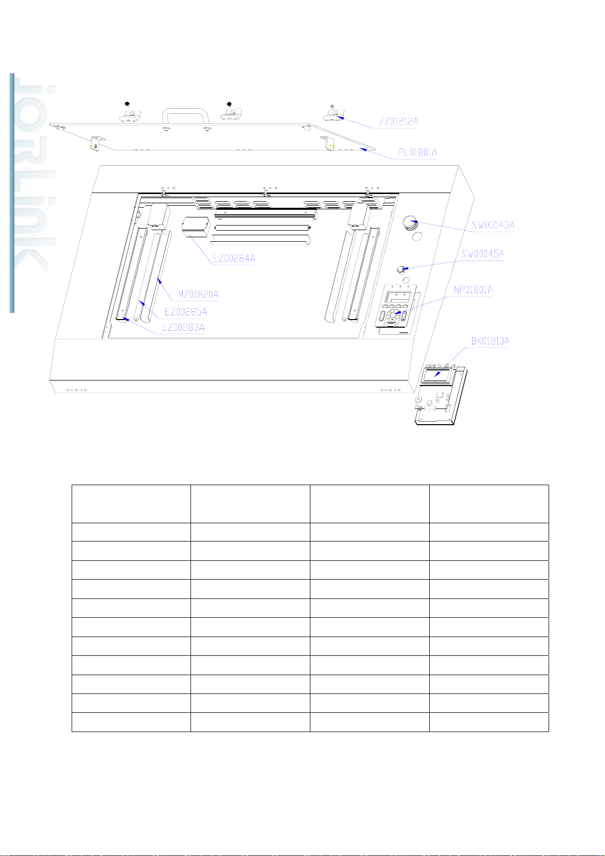
2-1. Top Cover for Spirit SI, GE, GX
Distributed & Supported by: Jorlink USA, Inc. | Tel: (336) 288-1613 | [email protected] | www.JORLINK.com
7/60
Parts Number for SI Parts Number for GE Parts Number for GX Parts Name
ZZ01212A 26500166 26500166G Window hinge
PL01801A 22801557 22802102G Window
SW00043A 25700035 25700035G Emergency switch
SW00045A 25700032 25700032G Lamp switch
NP01801A 23400020 23400020G Control panel sticker
BK01810A 23800145 23800145G Spirit keyboard module
EZ00284A N/A N/A DC 12V 8W ballast
MZ01820A 23300296 23300296G Light shade
EZ00285A N/A N/A 8W fluorescent light
EZ00283A 22000124 22000124G Lamp holder
29004037 29004037 29004037G LED light
6
Page 8
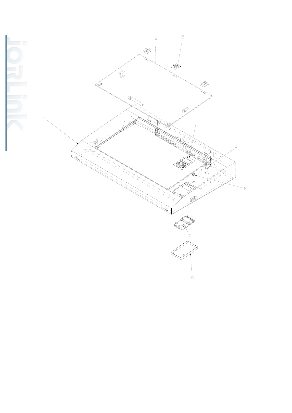
2-1. Top Cover for Spirit LS
Distributed & Supported by: Jorlink USA, Inc. | Tel: (336) 288-1613 | [email protected] | www.JORLINK.com
8/60
ITEM PARTS NUMBER PARTS NAME QTY.
1 29006263G Top Cover assembly 1
2 26500166G Window Hinge 3
3 29003833G Window Assembly 1
4 25700094G Key Switch 1
5 23400020G Control panel sticker 1
6 24400995G Key board 1
Key Switch to Emergency Stop
7 20901927G
1
Switch Cable
8 29005274G Keyboard Assembly 1
7
Page 9
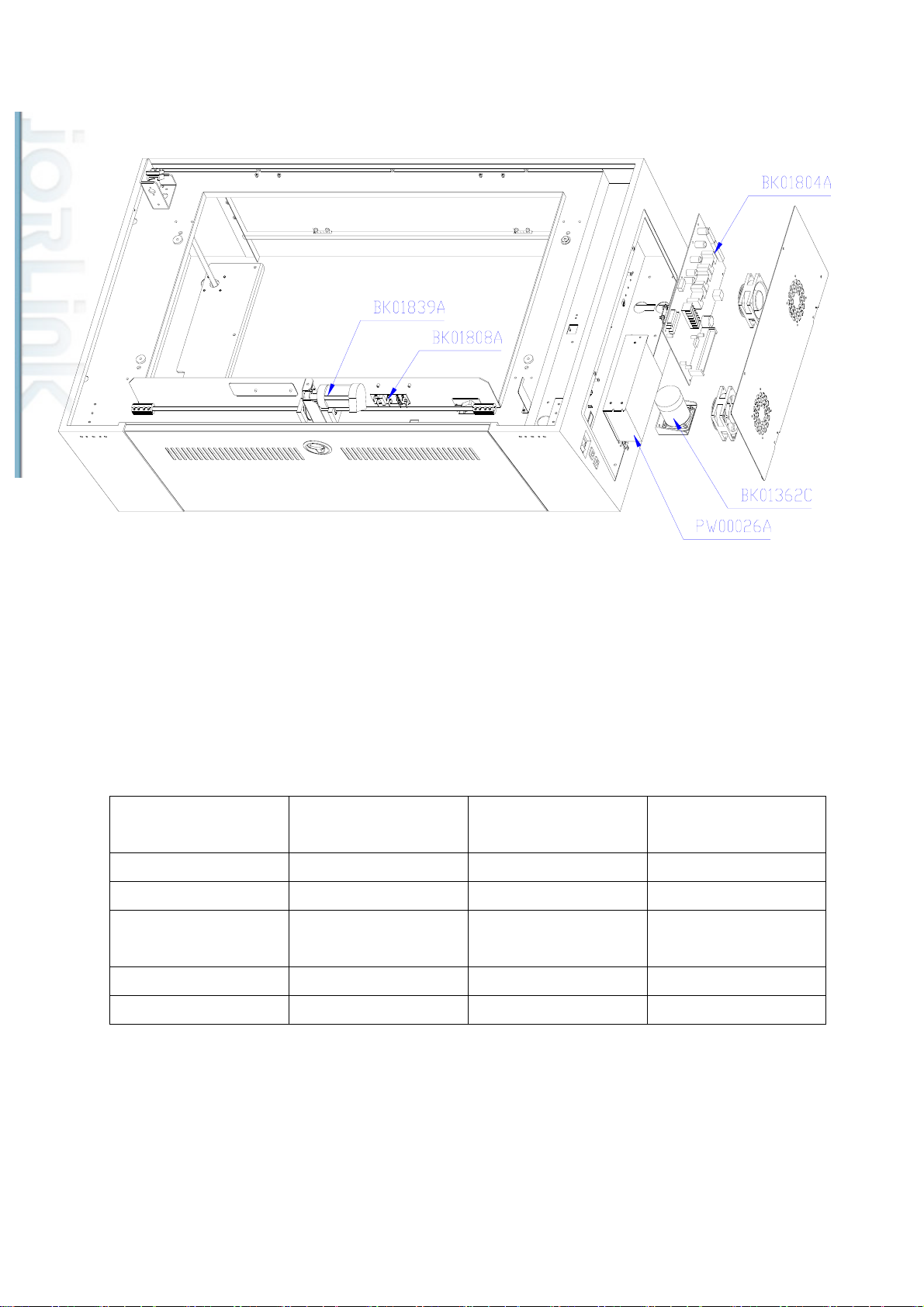
3. Mid Section
Distributed & Supported by: Jorlink USA, Inc. | Tel: (336) 288-1613 | [email protected] | www.JORLINK.com
9/60
Parts number for SI Parts Number for GE
Parts Number for GX Parts name
& LS
BK01804A 29002506 29005033G Spirit main board
BK01362C 29001141 29001141G Z motor assembly
PW00026A 24500022 24500022G Meanwell power
supply 40/5V
BK01839A 29002537 29002537G Motor group
BK01808A 29002510 29002510G Y motor PCB
8
Page 10
Distributed & Supported by: Jorlink USA, Inc. | Tel: (336) 288-1613 | [email protected] | www.JORLINK.com
10/60
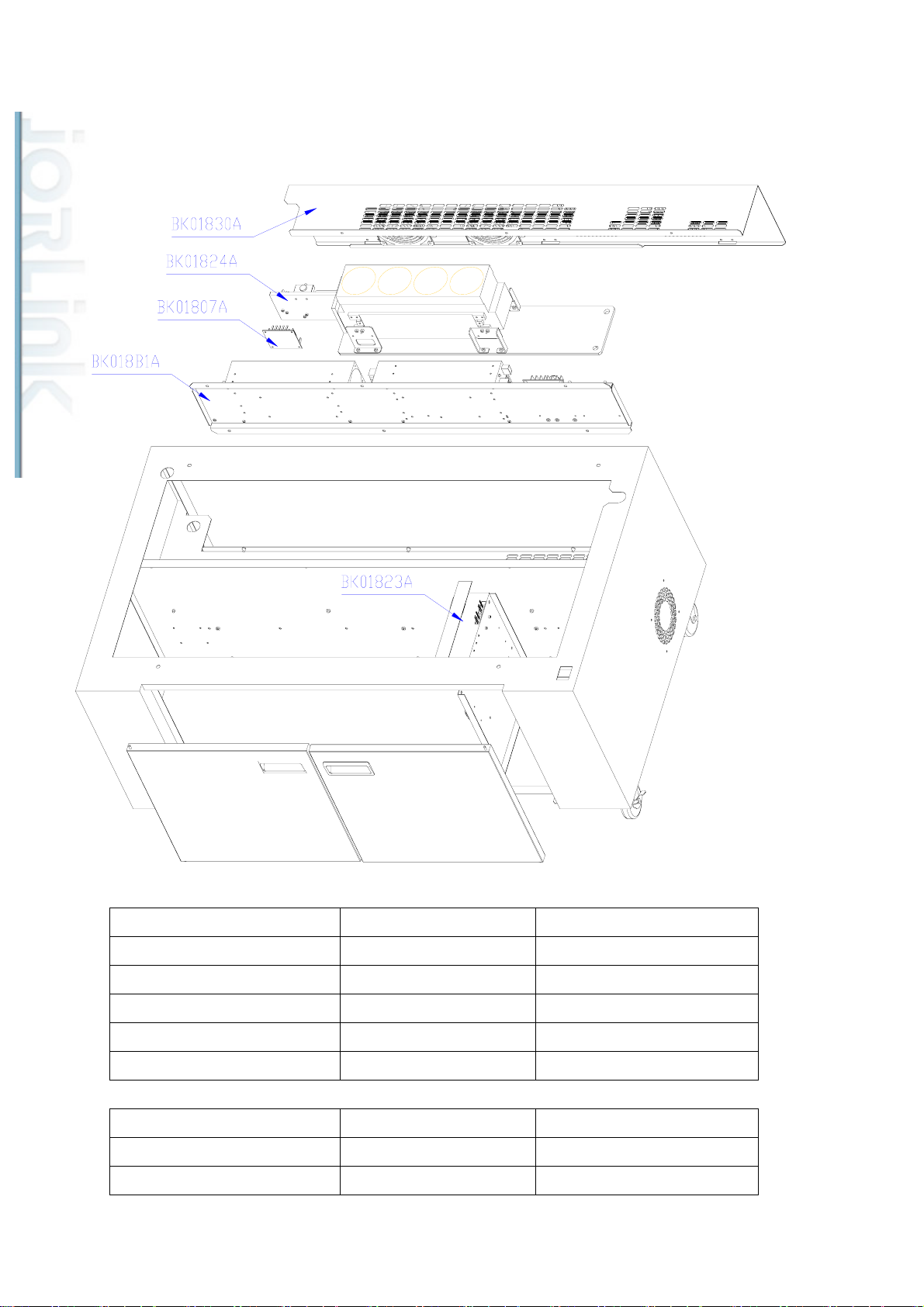
4. Base Section
Parts number for SI Parts Number for SI LS Parts name
BK01830A←1 29003272G←1
BK01824A←2 29003651G←2
BK01807A←3 29005059G←3
Base back door assembly
12W system Assembly
DC12V POWER MODULE
BK018B1A←4 29002557G←4
BK01823A←5 29003783G←5
12W power supply fixture
12V Power block
Parts number for SI Parts Number for SI LS Parts name
BK01830A←1 29003271G←1
BK01824A←2 29003652G←2
9
Base back door assembly
25W system Assembly
Page 11
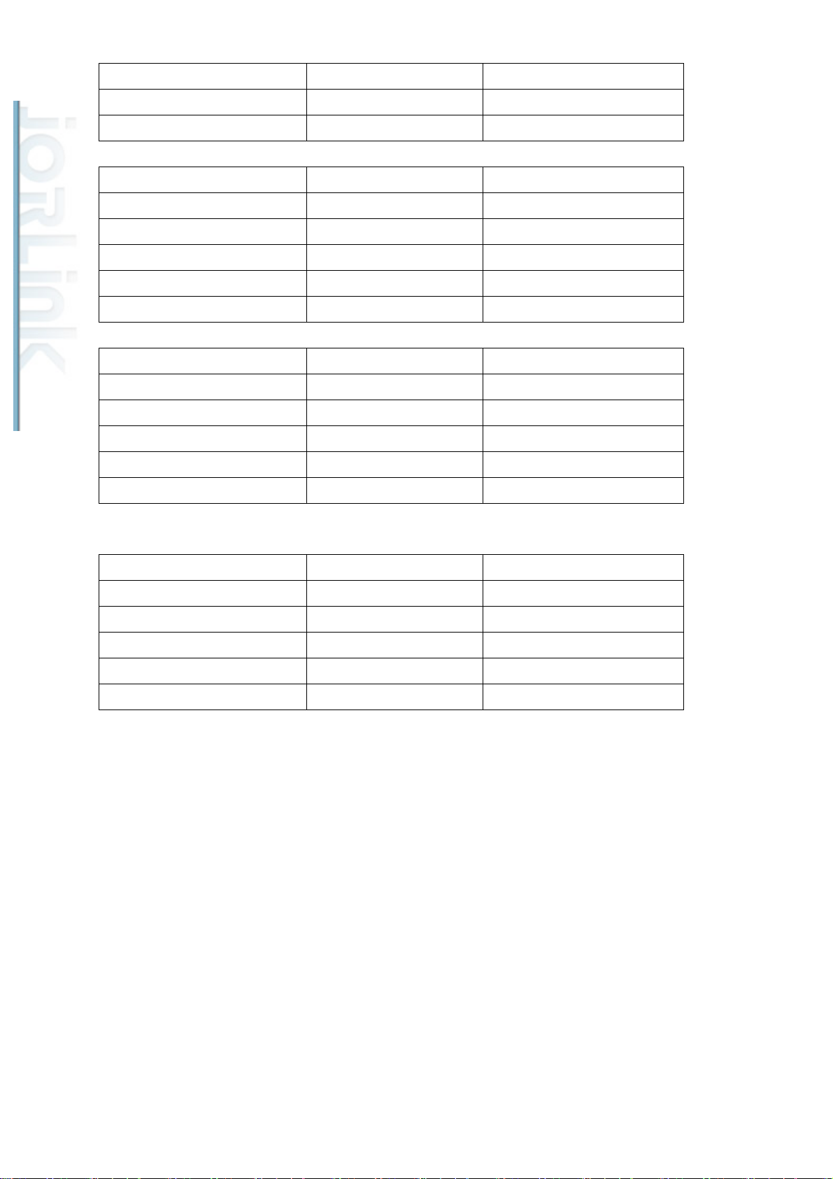
BK01807A←3 29005059G←3
Distributed & Supported by: Jorlink USA, Inc. | Tel: (336) 288-1613 | [email protected] | www.JORLINK.com
11/60
DC12V POWER MODULE
BK018B1A←4 29002562G←4
BK01823A←5 29003783G←5
25W power supply fixture
12V Power block
Parts number for SI Parts Number for SI LS Parts name
BK01830A←1 29003629G←1
BK01824A←2 29004123G←2
BK01807A←3 29005059G←3
BK018B1A←4 29003971G←4
BK01823A←5 29003783G←5
Base back door assembly
V30 system Assembly
DC12V POWER MODULE
V30 power supply fixture
12V Power block
Parts number for SI Parts Number for SI LS Parts name
BK01830A←1 29003267G←1
BK01824A←2 29003659G←2
BK01807A←3 29005059G←3
BK018B1A←4 29002587G←4
BK01823A←5 29003783G←5
Base back door assembly
V40 system Assembly
DC12V POWER MODULE
40C power supply fixture
12V Power block
Parts number for SI Parts Number for SI LS Parts name
BK01830A←1 29003629G←1
BK01824A←2 29003632G←2
BK01807A←3 29005059G←3
BK018B1A←4 29004228G←4
BK01823A←5 29003783G←5
Base back door assembly
60W system Assembly
DC12V POWER MODULE
T60 power supply Assembly
12V Power block
10
Page 12
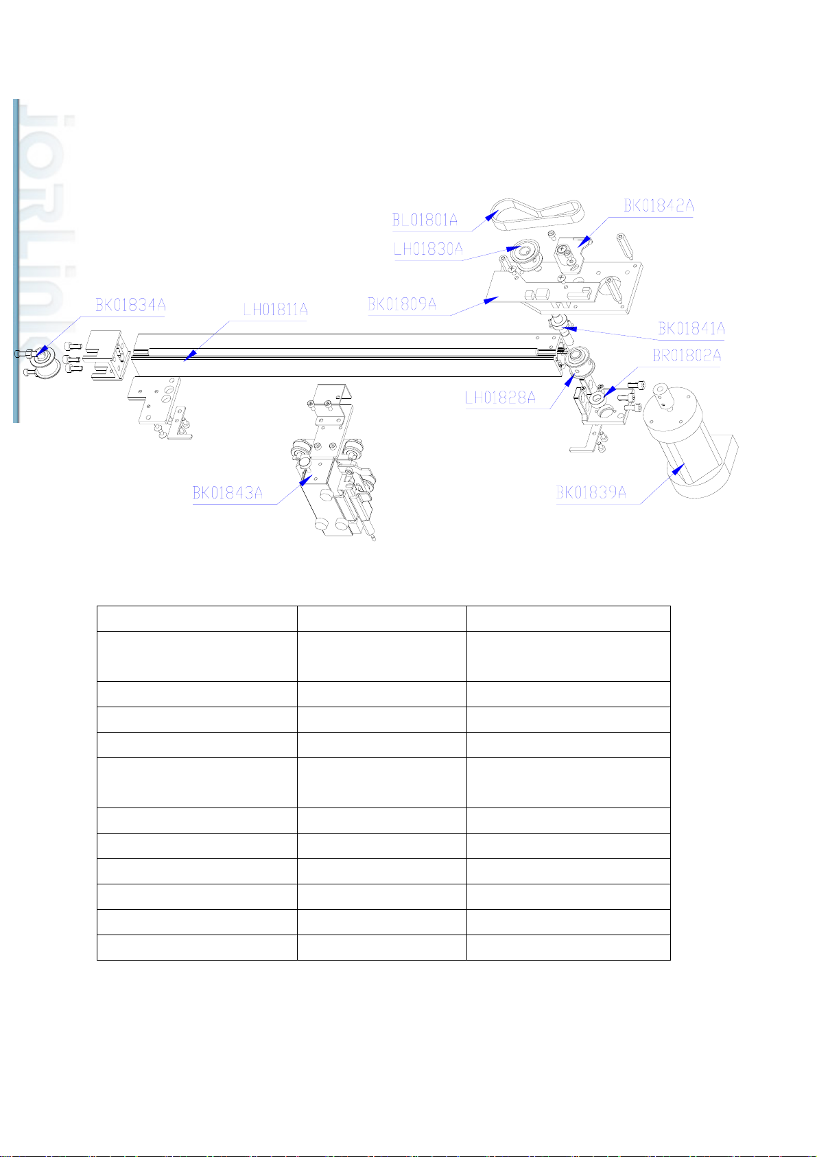
5. X-axis assembly for Spirit SI/GE
Distributed & Supported by: Jorlink USA, Inc. | Tel: (336) 288-1613 | [email protected] | www.JORLINK.com
12/60
Parts number for SI Parts Number for GE Parts name
BK01842A 29002540 X axis transmission pulley
assembly
BL01801A 20600074 X axis belt
LH01830A 22800940 X axis mid belt wheel
BK01809A 29002511 X motor module
BK01841A 29002539 X axis transmit shaft
assembly
LH01828A 22800938 X axis transmit belt wheel
BR01802A 20700053 Bearing
BK01839A 29002537 Motor group
LH01811A 22800923 X axis slideway
BK01834A 29002533 Tension idle pulley assembly
BK01843A 29002541 Lens carriage assembly
11
Page 13
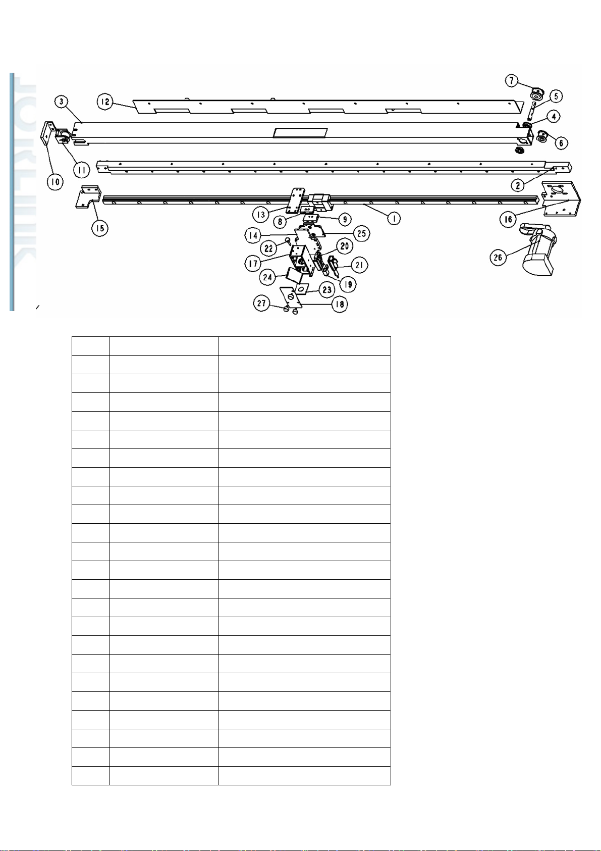
5-1. X-axis assembly for Spirit GX (including lens carriage assembly)
Distributed & Supported by: Jorlink USA, Inc. | Tel: (336) 288-1613 | [email protected] | www.JORLINK.com
13/60
No Part number for GX Part name for GX
1 23300265G X axis linear guide
2 22800673G x axis main beam
3 22800672G X-axis beam - 1
4 20700037G bearing
5 22800823G X-axis pulley core (right)
6 22800686G X Pulley_30 teeth gear
7 22800664G X pulley_36 teeth gear
8 22800683G Carrage belt plate (up)
9 22800684G Carrage belt plate (down)
10 22800205G x axis belt adjuster
11 29000302G X-Axis idel Pulley fixture
12 24400644G X-cable-carrier bracket
13 22800213G X-cable-carrier
14 22802108G Lens carriage connect board
15 22802109G Linear guide Left bracket
16 22802110G Linear guide Right bracket
17 22801996G Lens carriage Assembly-C180
18 22802084G Lens carriage front cover - C180
19 22800955G carriage airflow valve
20 29002546G Auto focus seat Assembly
21 29002547G Auto focus pin Assembly
22 29000706G Hand Knobs(M3-16)
23 22802117G air nozzle - C180
12
Page 14

24 29004736G Carriage mirror Holder
Distributed & Supported by: Jorlink USA, Inc. | Tel: (336) 288-1613 | [email protected] | www.JORLINK.com
14/60
25 22802107G Lens carriage base
26 29004980G SPIRIT GX X-AXIS MOTOR SET
27 23300298G Hand Knobs(CRKB.M3-6L)
13
Page 15
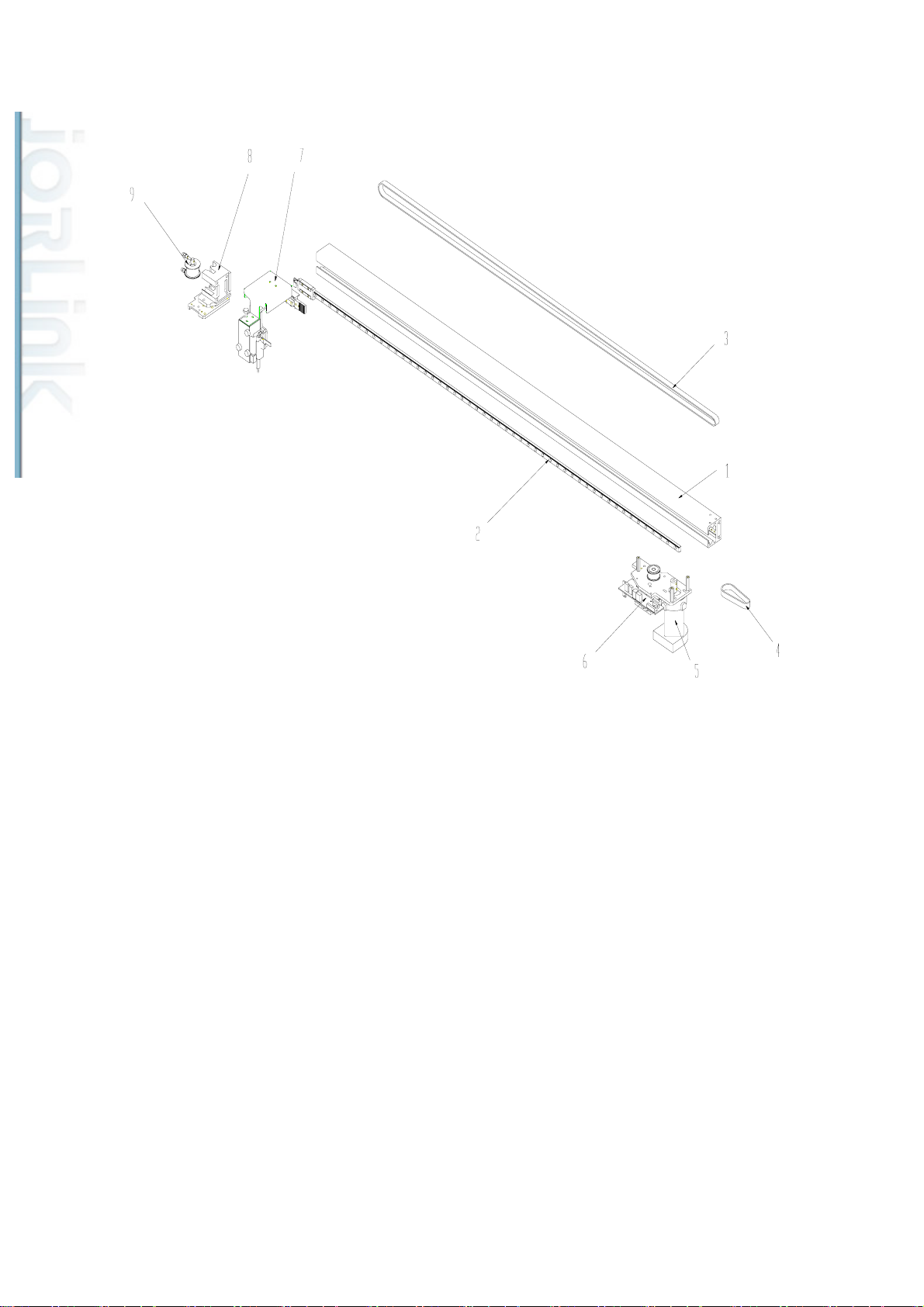
5-2. X-axis assembly for Spirit LS
Distributed & Supported by: Jorlink USA, Inc. | Tel: (336) 288-1613 | [email protected] | www.JORLINK.com
15/60
ITEM PARTS NUMBER PARTS NAME QTY
1 23301231G linear guide(MGN9C1R800Z0CM<E10>) 1
2 22803045G x axis slideway 1
4 20600176G Open Steel Filum Belt (U2GT-1794-15) 1
5 29002537G X motor assembly 1
6 29005107G X motor PCB(AAS I) - Spirit 1
7 29005506G Lens carriage Assembly 1
8 22803049G Tension pulley shaft bracket 1
9 29006039G Tension idle pulley Assembly 1
14
Page 16
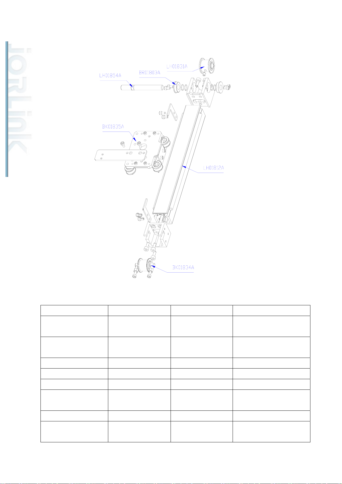
6. Y-axis assembly
Distributed & Supported by: Jorlink USA, Inc. | Tel: (336) 288-1613 | [email protected] | www.JORLINK.com
16/60
Parts number for SI Parts Number for GE Parts Number for GX Parts name
29005867G 29002531G 29004576G Y-Axis Rail
Assembly(Left)
29005866G 29002532G 29004577G Y-Axis Rail
Assembly(Right)
LH01831A 22800941 22800941 Y axis transmit belt wheel
BR01803A 20700054 20700054 Bearing
LH01854A 22800950 22800950 Y axis passive axle center
BK01835A 29002534 29002534 Double side mount
assembly
LH01812A 22800924 22802104G Y axis slide way
BK01834A 29002533 29002533 Tension idle pulley
assembly
15
Page 17
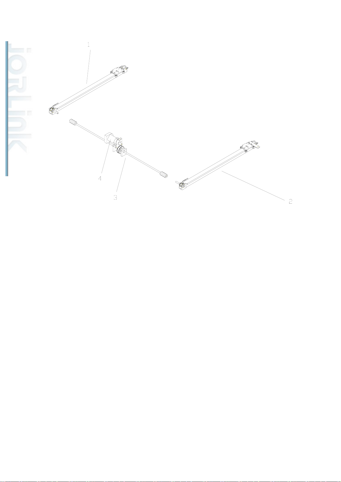
6-1. Y-axis assembly for Spirit LS
Distributed & Supported by: Jorlink USA, Inc. | Tel: (336) 288-1613 | [email protected] | www.JORLINK.com
17/60
ITEM PARTS NUMBER PARTS NAME QTY.
1 29005927G Y-Axis Rail Assembly(left) 1
2 29005928G Y-Axis Rail Assembly(right) 1
3 29006390G Y Transmit Shaft Assembly 1
4 29002537G Y Motor assembly 1
16
Page 18
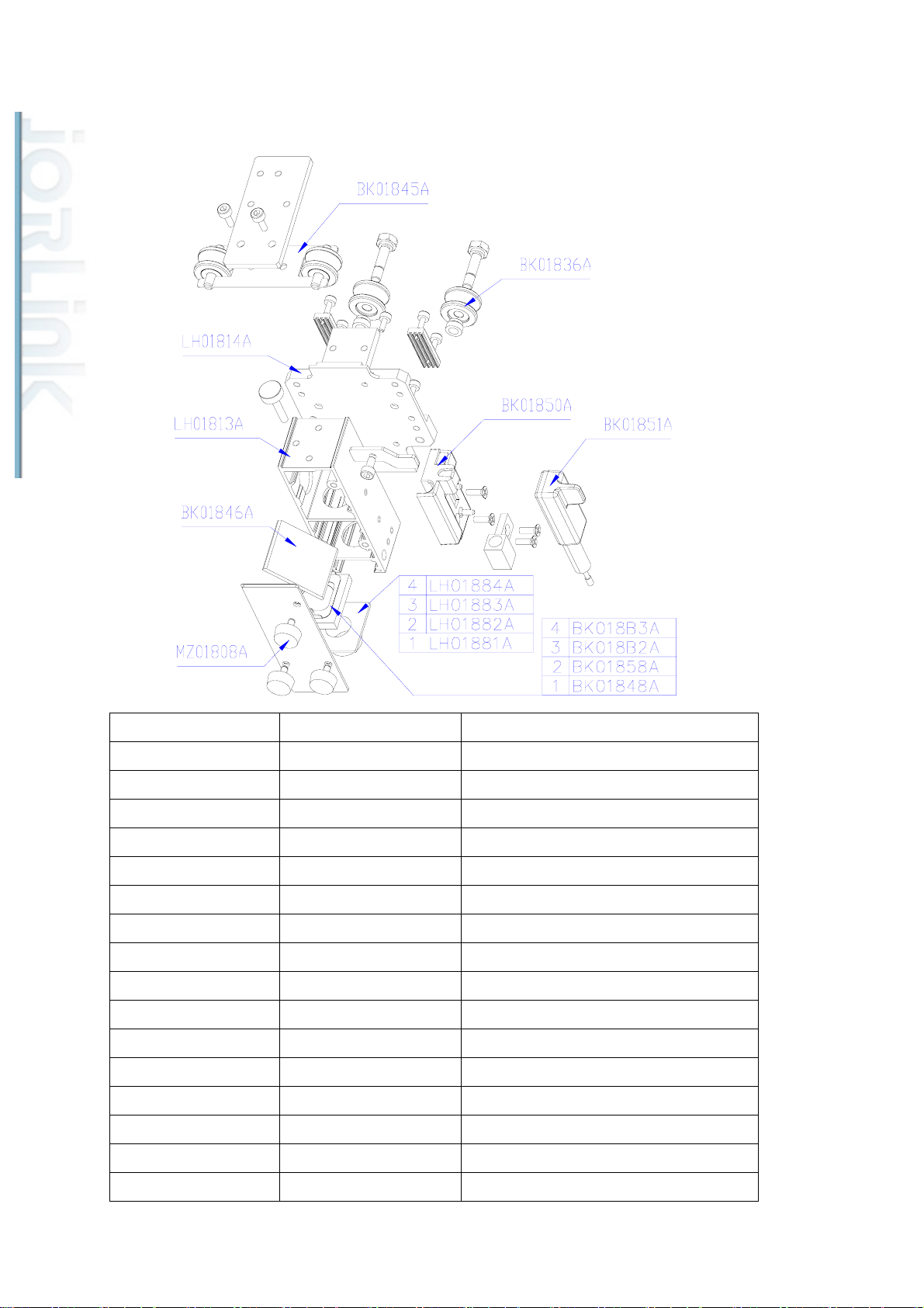
7. Pen carriage for Spirit SI/GE
Distributed & Supported by: Jorlink USA, Inc. | Tel: (336) 288-1613 | [email protected] | www.JORLINK.com
18/60
Parts number for SI Parts Number for GE Parts Number
BK01845A 29002543 Wheel spring assembly
BK01836A 29002535 Unilateral wheel
LH01814A 22800925 Lens carriage base
LH01813A 22801018 Lens carriage organize
BK01850A 29002546 Auto focus seat assembly
BK01851A 29002547 Auto focus pin assembly
BK01846A 29002544 Carriage reflector hold assembly
MZ01808A 23300298 Hand knobs
BK018B3A 29002589 4.0” focal lens assembly
BK018B2A 29002588 2.5” focal lens assembly
BK01858A 29002554 1.5” focal lens assembly
BK01848A 29002545 2.0” focal lens assembly
LH01884A N/A Air nozzle (4“ inch)
LH01883A 22801216 Air nozzle (for cloth)
LH01882A 22801217 Air nozzle (enhance)
LH01881A 22800962 Air nozzle
17
Page 19
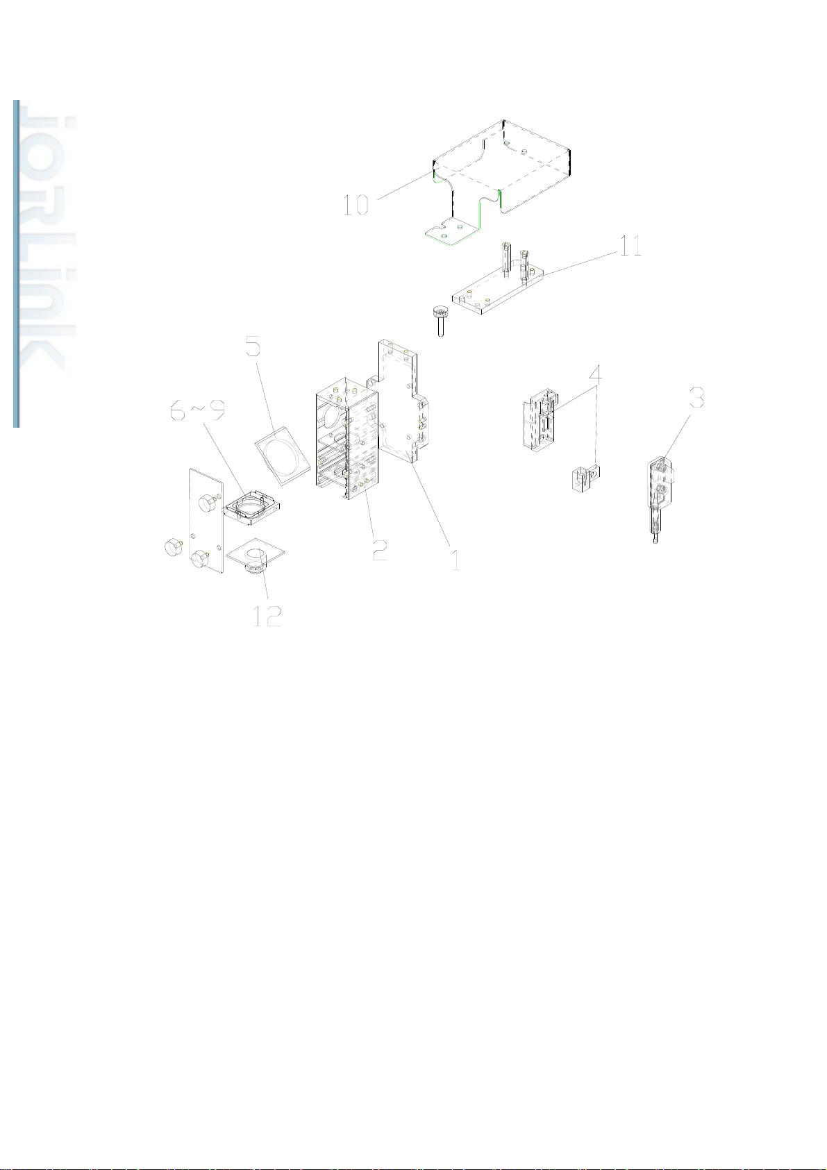
7-1. Pen carriage for Spirit LS
Distributed & Supported by: Jorlink USA, Inc. | Tel: (336) 288-1613 | [email protected] | www.JORLINK.com
19/60
ITEM PARTS NUMBER PARTS NAME QTY.
1 22802108G Lens carriage roconnect board - 1
2 22801996G Lens carriage Assembly-V2 1
3 29006010G Auto focus pin Assembly 1
4 29002546G Auto focus seat Assembly 1
5 29004736G Carriage Reflector Hold 1
6 29002545G 2.0" Focal lens Assembly 1
7 29002554G 1.5" Focal lens Assembly 1
8 29002588G 2.5" Focal lens Assembly 1
9 29002589G 4.0" Focal lens Assembly 1
10 24403536G Lens carriage top shingle 1
11 22802917G Lens carriage assist base 1
12 22802117G air nozzle 1
18
Page 20
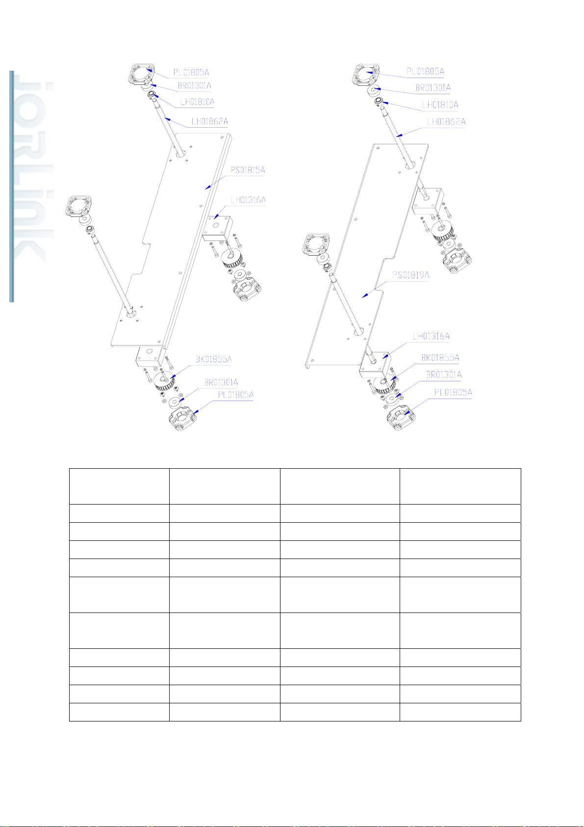
8. Z-platform
Distributed & Supported by: Jorlink USA, Inc. | Tel: (336) 288-1613 | [email protected] | www.JORLINK.com
20/60
Parts number for SI Parts Number for GE
Parts Number for GX Parts name
& LS
PL01805A 24100366 22802102G Bearing seat
BR01301A 20700034 20700034G Bearing
LH01810A 22800922 22800922G Z axis top stopper
LH01862A 22801022 22801022G Z axis table screw
PS01815A 29003638 24402291G Working table bracket
(left)
PS01819A 29003637 24402291G Working table bracket
(right)
LH01316A 22800130 22800130G Z axis screw thread
BK01855A 29002551 29002551G Z axis pulley assembly
BR01301A 20700034 20700034G Bearing
PL01805A 24100366 24100366G Bearing seat
19
Page 21
Distributed & Supported by: Jorlink USA, Inc. | Tel: (336) 288-1613 | [email protected] | www.JORLINK.com
21/60
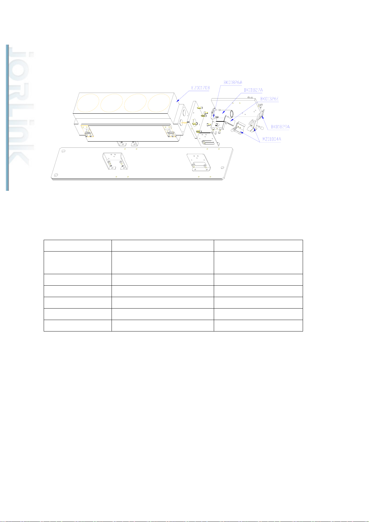
9. Mirror 1/Laser unit
Parts number for SI Parts Number for GE/GX Parts name
EZ00170B N/A 30W laser tube (depends on
model)
BK01826A N/A Red pointer assembly
BK01827A N/A 3X beam expander
BK01326E N/A Red pointer mirror
BK01829A N/A Mirror 1 assembly
MZ01804A N/A Prism mounts assembly
20
Page 22
Distributed & Supported by: Jorlink USA, Inc. | Tel: (336) 288-1613 | [email protected] | www.JORLINK.com
22/60
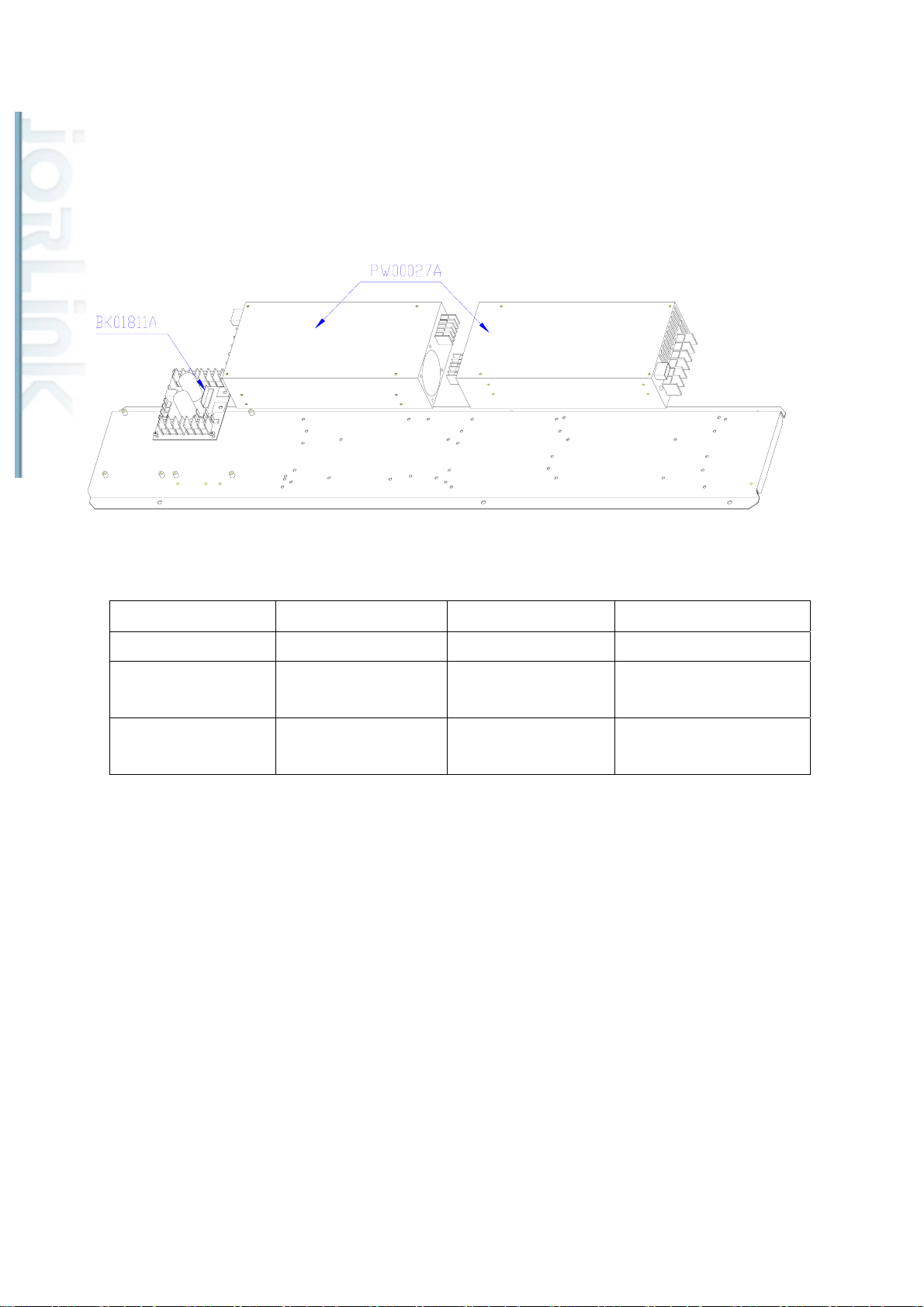
10. Power supply
Parts number for SI Parts Number for GE Parts Number for GX Parts name
BK01811A 29002513 29002513G Laser power adapter
PW00027A N/A N/A Power supply PSP-600
49V
N/A 24500032 24500032G Power supply ASNER
800W 30V
21
Page 23
Distributed & Supported by: Jorlink USA, Inc. | Tel: (336) 288-1613 | [email protected] | www.JORLINK.com
23/60
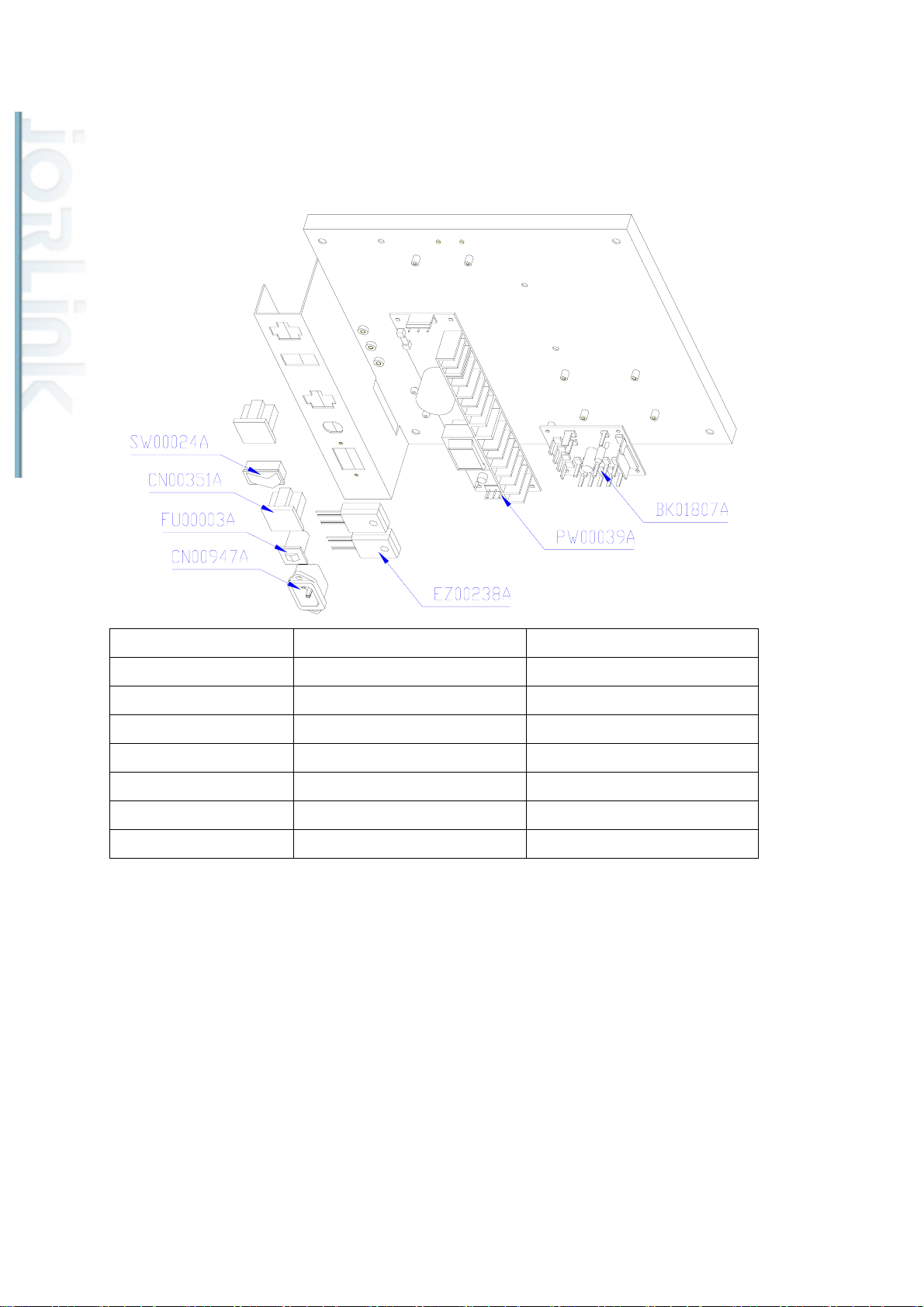
11. Base section side panel (SI)
Parts number for SI Parts Number for GE/GX Parts name
SW00024A N/A Rocker switch SW-115
CN00351A N/A AC plug
FU00003A N/A Fuse
CN00947A N/A AC connector
EZ00238A N/A SSR KSD215AC3
PW00039A N/A Power LPS-75-12 DC 12V
BK01807A N/A DC 12V module
22
Page 24
Section 2. Power System
Distributed & Supported by: Jorlink USA, Inc. | Tel: (336) 288-1613 | [email protected] | www.JORLINK.com
24/60
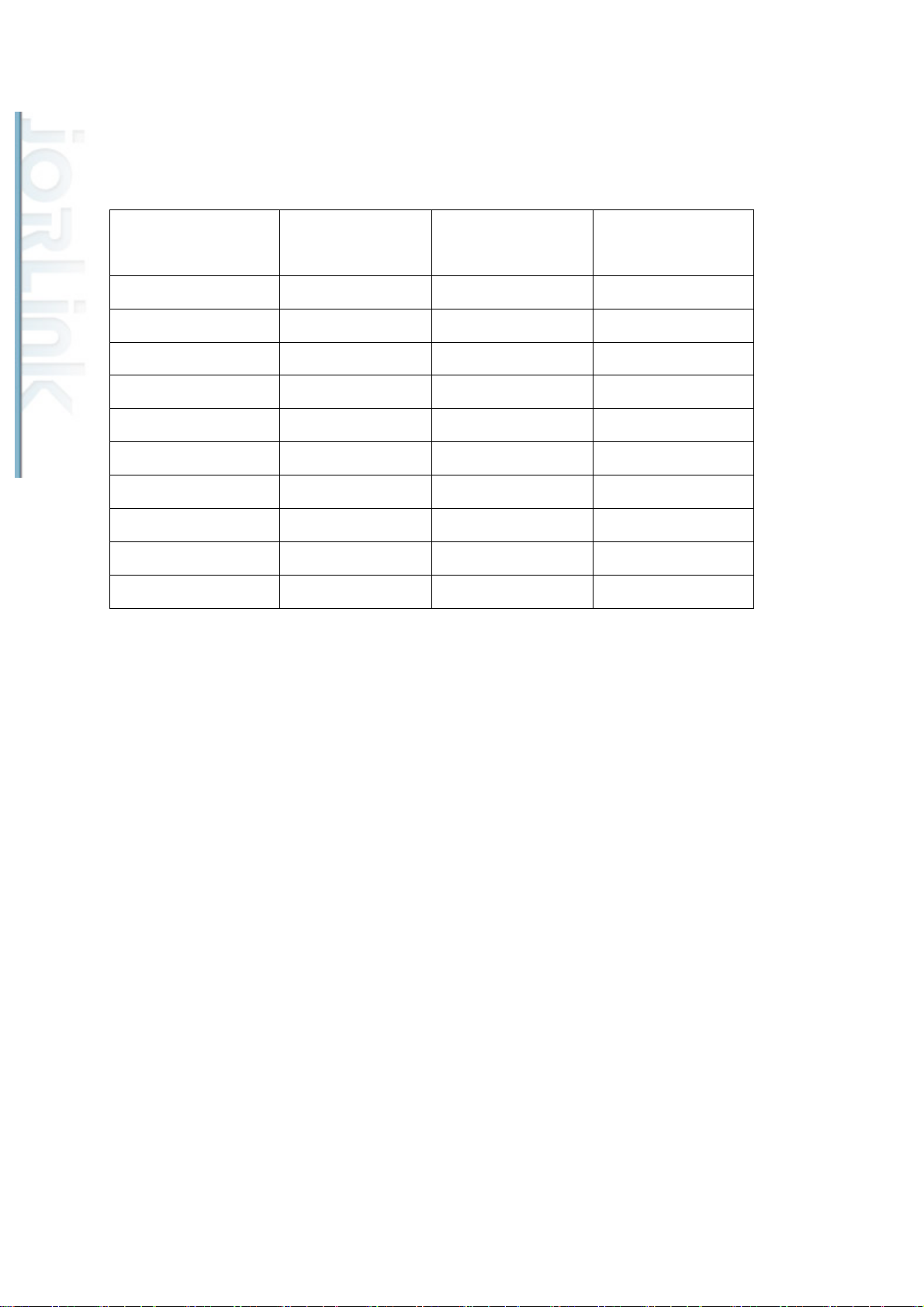
Refer to the following chart for the number of power supplies and parts number that
is equipped with your Spirit.
Machine Model Laser Tube Number of Power
Supplies
Power supply parts
Number
SI-12W Synrad 48-1 series 1 PW00011A
SI-25W Synrad 48-2 series 1 PW00012A
SI-30W Deos 2 PW00027A
SI-40W Deos 2 PW00027A
SI-60W Deos 3 PW00027A
SI-100W G-100 5 PW00027A
GE-30W, GX-30W V-30 1 24500032
GE-40W, GX-40W V-40 1 24500032
GE-60W, GX-60W T-60 2 24500032
GE-100W, GX-100W T-100 4 24500032
The normal voltage output of the power supply for Spirit SI should be at 48V and for
Spirit GE should be at 30V. To measure the output voltage of the power supply unit, use a
multi-meter to get the voltage reading at the immediate output location.
23
Page 25
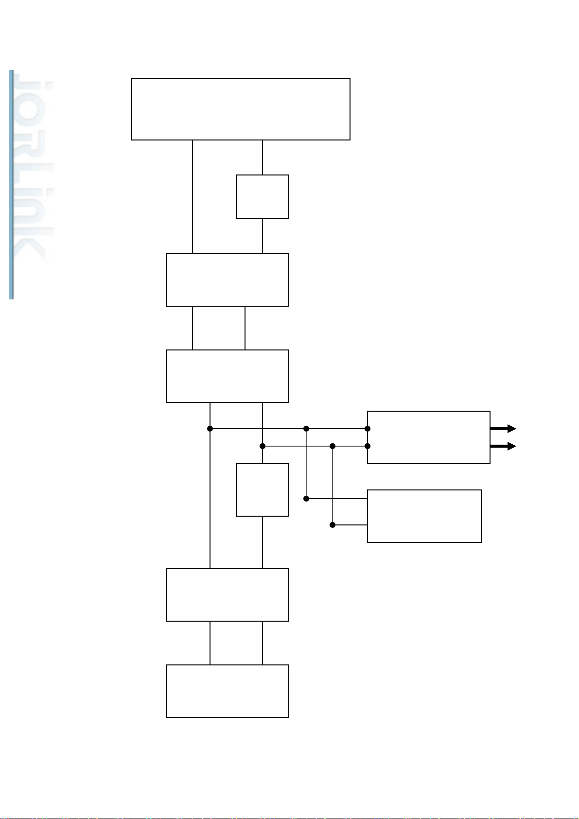
10W~25W Power Cable Layout Diagram (SI)
Distributed & Supported by: Jorlink USA, Inc. | Tel: (336) 288-1613 | [email protected] | www.JORLINK.com
25/60
AC 100V-AC240V
INPUT
15A
FUSE
ON/OFF
Switch
EMI
Line Filter
POWER
BOARD
Main
BOARD
3A
FUSE
POWER SUPPLY
LASER
FAN&LAMP
POWER SUPPLY
24
Page 26
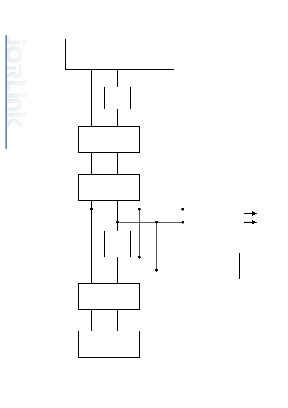
50W~75W Power Cable Layout Diagram (SI)
Distributed & Supported by: Jorlink USA, Inc. | Tel: (336) 288-1613 | [email protected] | www.JORLINK.com
26/60
AC 200V-AC240V
INPUT
15A
FUSE
ON/OFF
Switch
EMI
Line Filter
3A
FUSE
POWER
BOARD
Main
BOARD
POWER SUPPLY
LASER
FAN&LAMP
POWER SUPPLY
25
Page 27
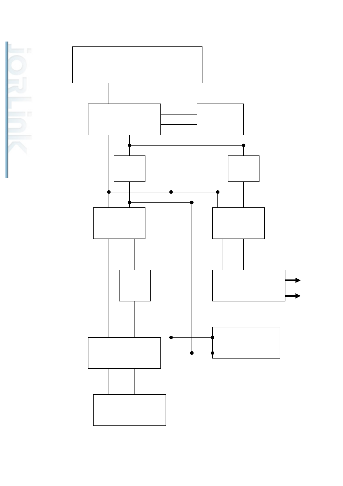
100W Power Cable Layout Diagram (SI)
Distributed & Supported by: Jorlink USA, Inc. | Tel: (336) 288-1613 | [email protected] | www.JORLINK.com
27/60
AC200~AC240V
INPUT
Relay
Switch
15A
FUSE
EMI
Line Filter
ON/OFF
Switch
20A
FUSE
EMI
Line Filter
3A
FUSE
POWER
BOARD
Main
BOARD
POWER SUPPLY
LASER
FAN&LAMP
POWER SUPPLY
26
Page 28
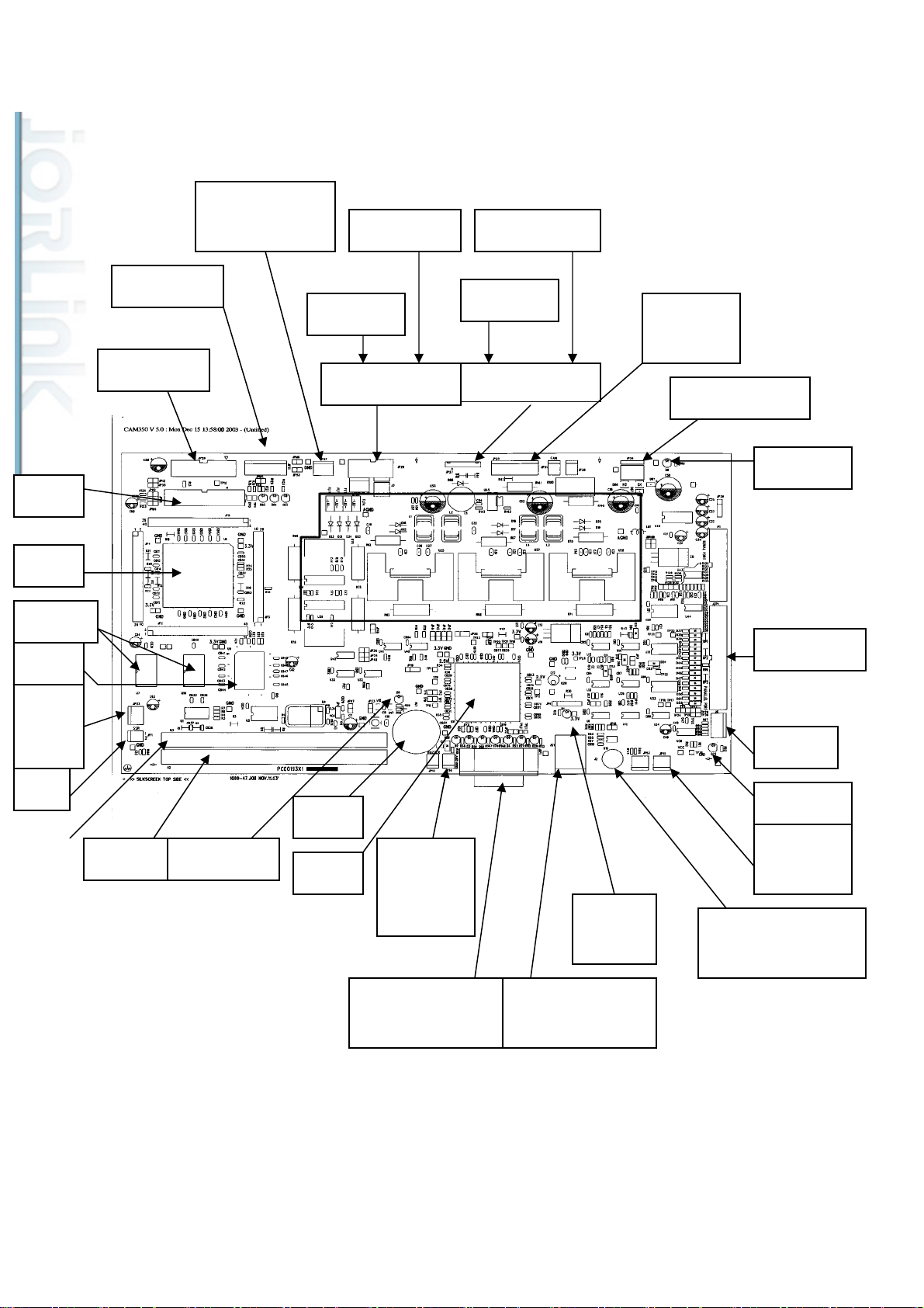
Section 3: Electrical System
Distributed & Supported by: Jorlink USA, Inc. | Tel: (336) 288-1613 | [email protected] | www.JORLINK.com
28/60
SPIRIT MAINBOARD DIAGRAM
BDM
CPU
FLASH
Door Switch
Control Panel
W o rkin g Table
Stepping Motor
UV SENSOR
Y- Motor
Y- MOTOR PCB
AutoFocus PCB
X- Motor
X-MOTOR PCB
Rotary
Attachment
Power (40V/5V)
Power
SRAM
Limit
Switch
SSR
SIMM1
Reset LED
Buzzer
FPGA
Laser Red
Beam
Diode
50W Laser Tube
D-SUB Cable
Parallel Port
USB Port
USB
30W Laser Tube
RJ-45 Cable
LOAD
10WLaser Tube
LED
BNC Cable
Control
P/S
27
Page 29
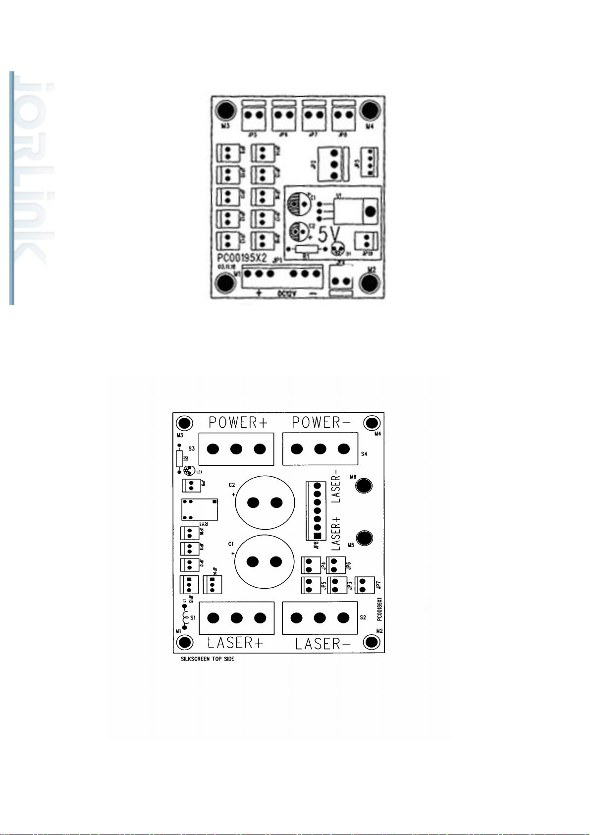
BK1807A DC12V Module
Distributed & Supported by: Jorlink USA, Inc. | Tel: (336) 288-1613 | [email protected] | www.JORLINK.com
29/60
BK01811A Laser Power Adaptor
28
Page 30
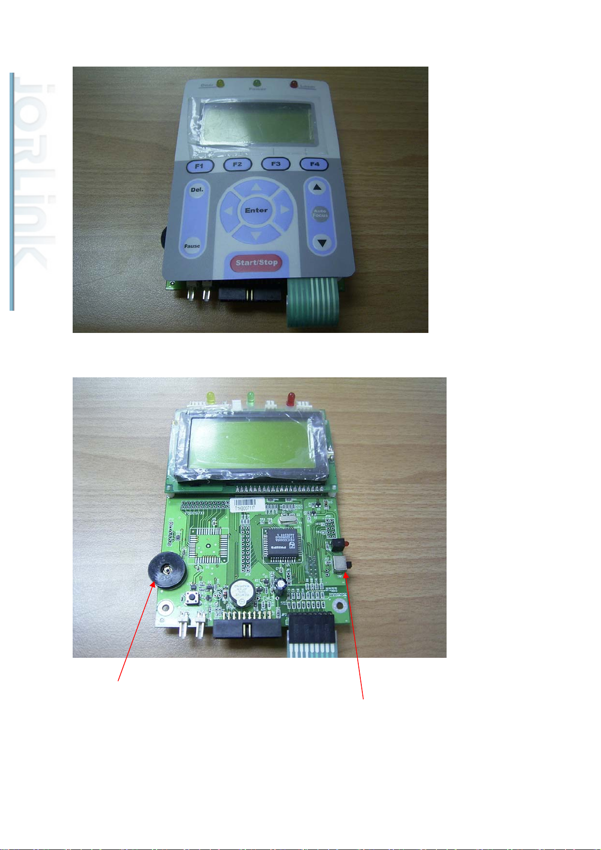
Control Panel
Distributed & Supported by: Jorlink USA, Inc. | Tel: (336) 288-1613 | [email protected] | www.JORLINK.com
30/60
Dial for adjusting contrast.
Load firmware button. (Button is at lower position at default.)
29
Page 31
Section 4: Laser System
Distributed & Supported by: Jorlink USA, Inc. | Tel: (336) 288-1613 | [email protected] | www.JORLINK.com
31/60
What is laser?
Laser is an acronym from Light Amplification by Stimulated Emission of Radiation.
Types of laser tubes
Synrad. There are 12W, 25W, 30W, 60W and 100W models with Synrad laser tubes and also
there are 30W, 40W, 60W, and 100W models with Coherent Deos laser tubes.
There are two types of laser sources used with the Spirit, namely Coherent-Deos and
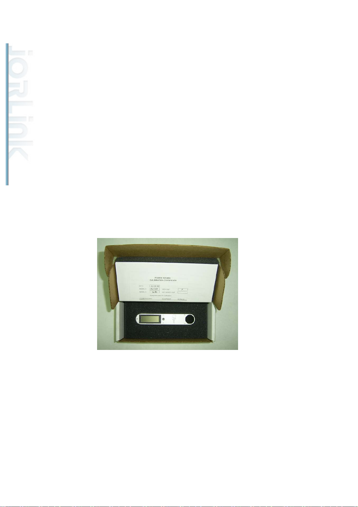
How to measure the power output of a laser tube?
(GCLPM2500AA) that will measure the heat generated and convert it to a power reading. The
best place to measure the laser output power is at the immediate output of the laser tube (before
to mirror 1).
In order to measure the power output of a laser tube, we need to use a power meter
30
Page 32
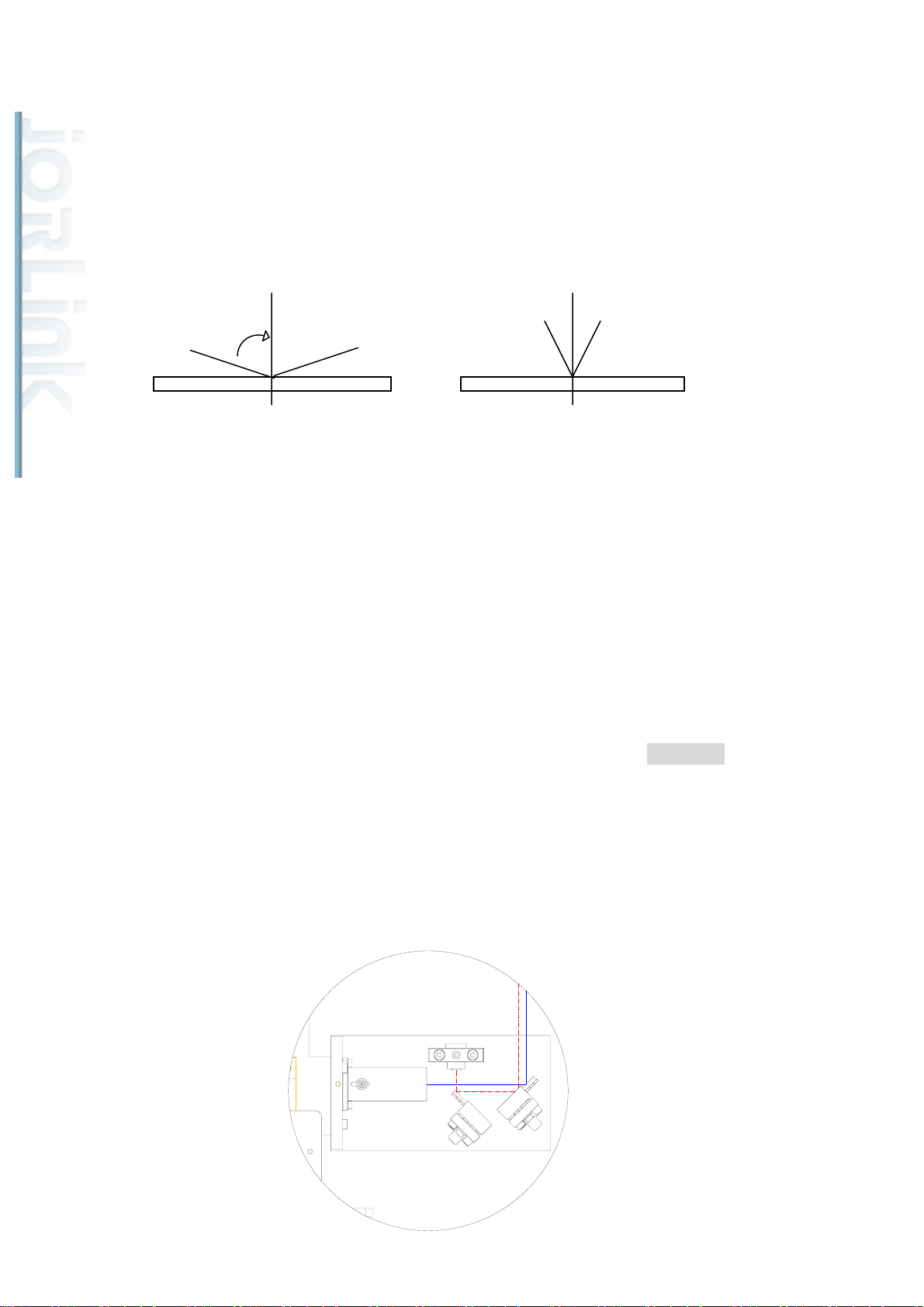
How does the laser beam travel to the working area?
Distributed & Supported by: Jorlink USA, Inc. | Tel: (336) 288-1613 | [email protected] | www.JORLINK.com
32/60
The laser beam generated by the laser source is reflected and guided by 4 optical lenses on
to the working area. Therefore the proper adjustment and maintenance of them are crucial.
Optical Alignment
Understanding Reflection.
X X Y Y
Light enters at an angle and leaves at an angle.
If light enters at an angle X, it will leave at an angle X.
If light enters at an angle Y, it will leave at an angle Y.
Beam Alignment
The laser beam is guided to the top of the working area by using 4 reflective mirrors.
Therefore, these mirror adjustments are crucial to the proper functioning of the machine. If the
laser beam is not aligned correctly, the beam path will be shifted or tilted and both rastering
and vectoring quality will be affected.
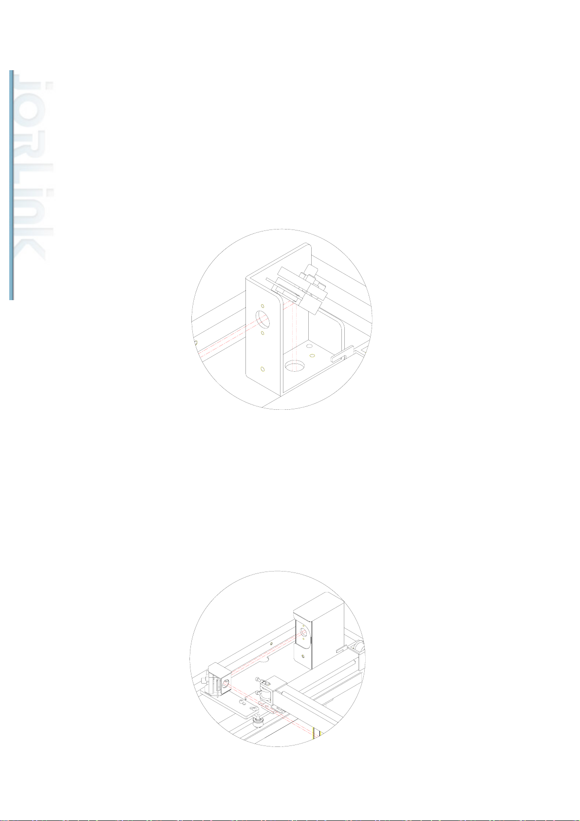
Step 1: Unscrew the back panel of the machine revealing the laser tube and Mirror 1. Turn on
the machine and enter the hidden diagnostic menu by holding down the Autofocus keys while
turning on the machine. Select test laser source. Set laser power to about 5%. Remove the
protective cover of Mirror 1 and remove Mirror 1. Place a cardboard or paper about 1.5 meters
away from the laser source. Fire the laser until you get a small burnt mark on the cardboard.
(Determine the laser beam and the red beam are aligned by seeing if the burnt hole is at the
exact location of the red beam. If they are not, adjust the red beam diode so that the red beam
and the burnt mark are at the same location.) Place Mirror 1 back to the mirror holder.
31
Page 33
Distributed & Supported by: Jorlink USA, Inc. | Tel: (336) 288-1613 | [email protected] | www.JORLINK.com
33/60
Step 2: Place a piece of masking tape over the tube opening that leads to Mirror 2. Fire the
laser and see if it leaves a burnt mark in the center of the hole. Also check that the burnt mark
left by the laser beam is circular in shape. If it is not circular , i.e. oval or other shape, then the
laser beam might have hit the inner tubing and get reflected on the way from Mirror 1 to
Mirror 2. If this is the case, place a piece of masking tape before the tube entrance, fire laser
and adjust Mirror 1 so that laser passes through the center of the opening.
Step 3: Place a masking tape on the opening before Mirror 3. Move the rail along the Y-axis so
that Mirror 3 is close to Mirror 2. Fire the laser and see if the laser beam goes through the
center of the circle. Then move the rail so that Mirror 3 is to the far end of Mirror 2. Fire the
laser and see if it leaves a mark at the same location when it was close to Mirror 2. Adjust
Mirror 2 repeatedly so that the burnt mark is at the center and on top of one another when
Mirror 3 is both close and far from Mirror 2.
32
Page 34
Distributed & Supported by: Jorlink USA, Inc. | Tel: (336) 288-1613 | [email protected] | www.JORLINK.com
34/60
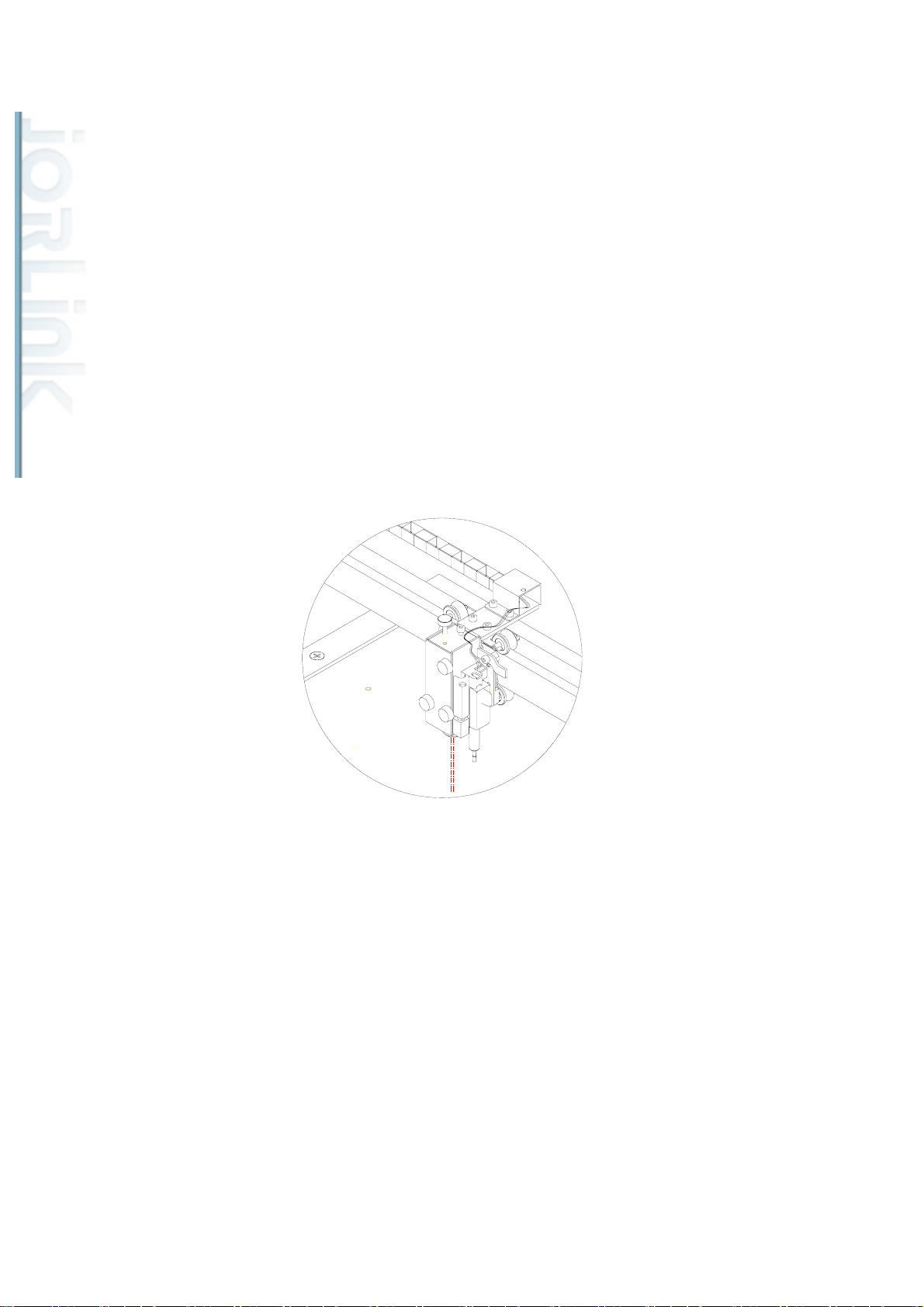
Step 4: Place a masking tape on the opening before Mirror 4. Move the pen carriage to the
upper left corner of the working area. Fire the laser and adjust Mirror 3 so the laser beam
passes through the center of the opening. Move the pen carriage to the upper right end of the
working table. Fire the laser and adjust Mirror 3 so the laser beam passes through the center of
the opening. The laser should pass through the same spot when the pen carriage is positioned at
upper left and upper right. Do the same for the bottom left corner and bottom right corner.
Place a masking tape over the nozzle opening. Position the pen carriage at one of the 4 corners
of the working area. Fire the laser and adjust Mirror 1 so the laser passes through the center of
the nozzle opening. Repeat for all 4 corners of the working area. After adjusting Mirror 1, you
may have to re-adjust Mirror 2 and Mirror 3 as well. (Repeating Steps 2 & 3.)
If the laser beam passes through the center of the nozzle opening at all 4 corners, then the laser
beam should have been aligned properly. Cut four 20x20 mm squares at the four corners of the
working area to double check that the edges of the square are not slanted
33
Page 35
Distributed & Supported by: Jorlink USA, Inc. | Tel: (336) 288-1613 | [email protected] | www.JORLINK.com
35/60
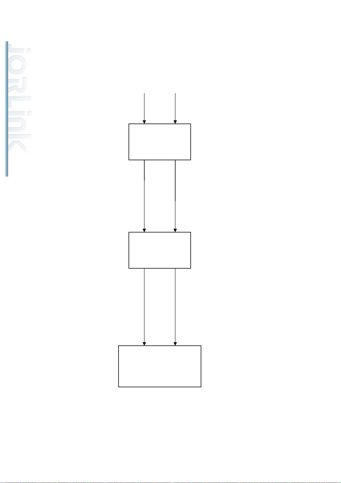
10W~25W Laser Tube Wiring Diagram (SI)
DC 30V
AC 110V/220V
DC Power
Supply 30V
POWER PCB
10W~25W
Laser Tube
34
Page 36
Distributed & Supported by: Jorlink USA, Inc. | Tel: (336) 288-1613 | [email protected] | www.JORLINK.com
36/60
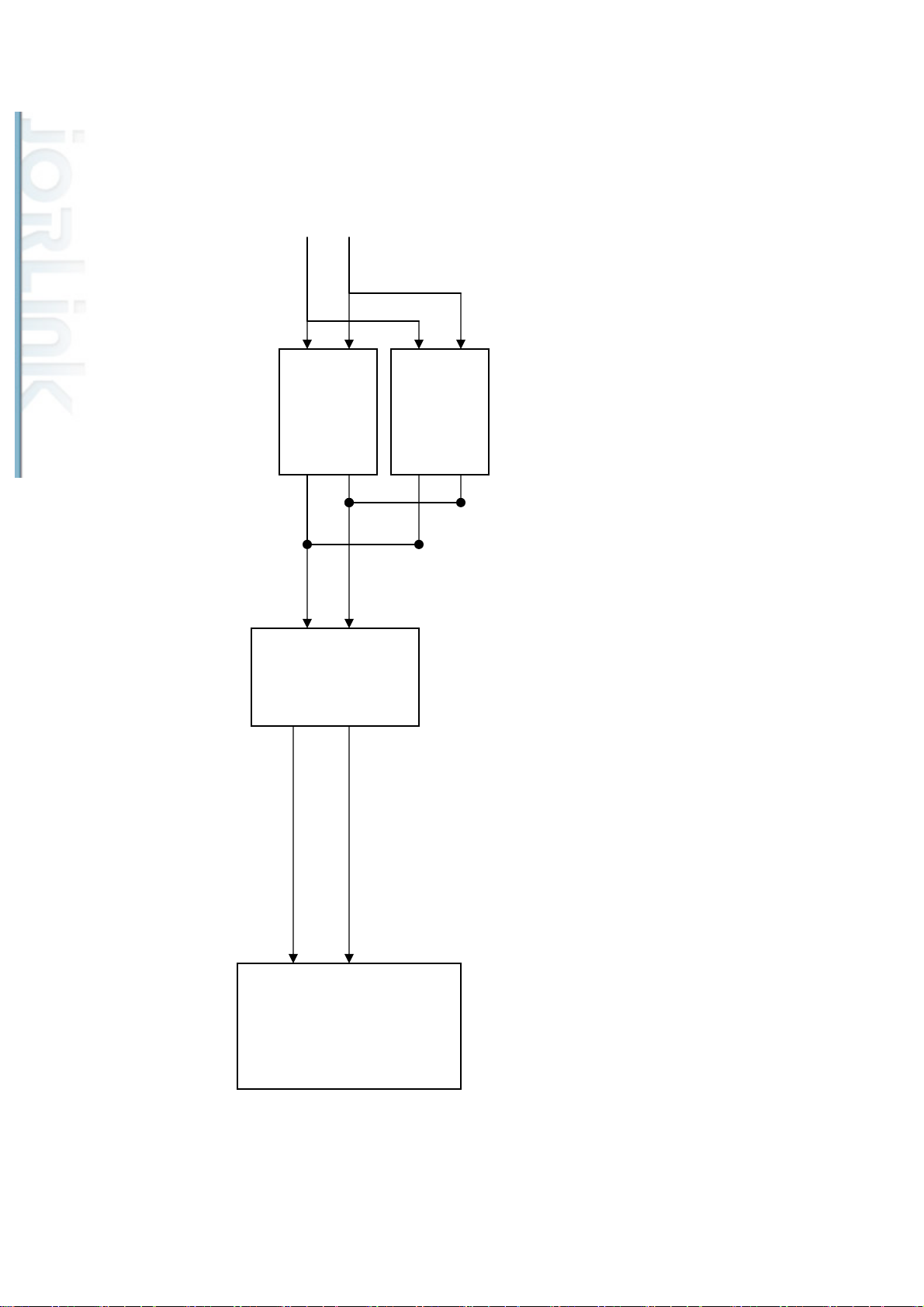
30~40W Laser Tube Wiring Diagram (SI)
AC 110V/220V
DC
Power
Supply
48V
POWER PCB
DC
Power
Supply
48V
DC 48V
30W~40W
Laser Tube
35
Page 37
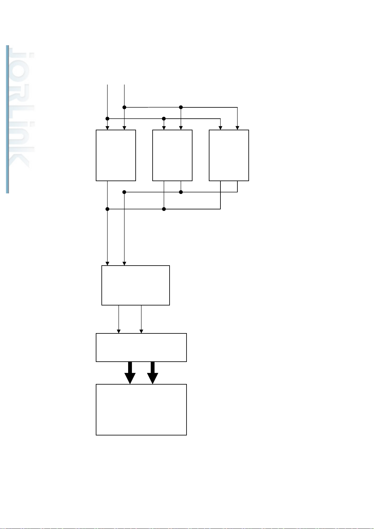
50W~75W Laser Tube Wiring Diagram (SI)
Distributed & Supported by: Jorlink USA, Inc. | Tel: (336) 288-1613 | [email protected] | www.JORLINK.com
37/60
AC 110V/220V
DC
Power
Supply
48V
DC 48V
DC
Power
Supply
48V
DC
Power
Supply
48V
POWER PCB
RF
50W~75W
Laser Tube
36
Page 38
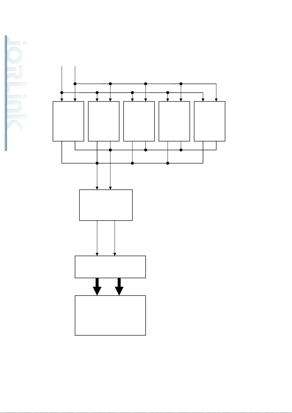
100W Laser Tube Wiring Diagram (SI)
Distributed & Supported by: Jorlink USA, Inc. | Tel: (336) 288-1613 | [email protected] | www.JORLINK.com
38/60
AC 220V
DC
Power
Supply
48V
POWER PCB
DC
Power
Supply
48V
DC
Power
Supply
48V
DC 48V
DC
Power
Supply
48V
DC
Power
Supply
48V
RF
100W
Laser Tube
37
Page 39
Section 5: Firmware
Distributed & Supported by: Jorlink USA, Inc. | Tel: (336) 288-1613 | [email protected] | www.JORLINK.com
39/60
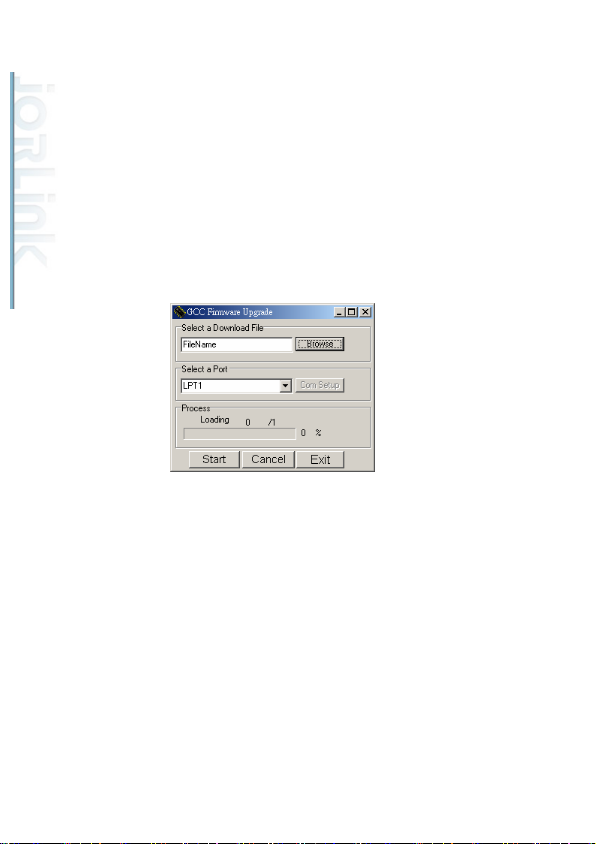
How to upgrade the firmware?
From www.gccworld.com website, you can logon with a distributor account and
download an utility tool called “uploader.exe” With this utility tool you can upgrade the
machine to the newest firmware or the firmware of your choice.
1. Turn on the machine while holding down the F2 button will allow you to send the
firmware via the parallel port.
2. Run the uploader.exe file.
3. Change the Com Setup to LPT1.
4. Locate the firmware file on your computer.
5. Click on the “Start” button and wait until the machine re-initialize.
38
Page 40

Chapter 2. System Diagnostics
Distributed & Supported by: Jorlink USA, Inc. | Tel: (336) 288-1613 | [email protected] | www.JORLINK.com
40/60
Section 1. Hidden Diagnostics
To enter the hidden Diagnostics menu, hold down the Autofocus button and turn on the
machine.
There are 11 tests under the hidden diagnostics menu.
1. LCM Key Test
LCM Key test will test the functionality of the keys on the keypad.
2. LCM Interface Test
LCM Interface test will display a series of different shapes on the LCM to allow user
to detect any malfunction on the display unit.
3. Parallel port test
Parallel port test checks that the parallel port is functional by asking the user to send a
file through the parallel port.
4. Serial port test
Serial port test checks that the serial port is functional by asking the user to send a file
through the serial port. (The serial port is for diagnostic purposes only. Please do not use.)
5. USB test
USB port test checks that the USB port is functional by asking the user to send a file
through the USB port.
6. DRAM test
DRAM test checks the functionality of the DRAM.
7. Laser test
Laser test allow you to fire the laser tube at a selected laser power. (This is also the
39
Page 41

utility that you use to perform beam alignment.)
Distributed & Supported by: Jorlink USA, Inc. | Tel: (336) 288-1613 | [email protected] | www.JORLINK.com
41/60
8. X motor test
X motor test checks that the X motor is functional by asking user to use the keys on
the control panel to move the pen carriage along the X axle.
9. Y motor test
Y motor test checks that the Y motor is functional by asking user to use the keys on
the control panel to move the pen carriage along the Y axle.
10. Z motor test
Z motor test checks that the Z motor is functional by asking user to use the keys on
the control panel to move the platform up and down the Z axle.
11. Hard Stop test
Hard Stop test checks that the X and Y sensors are functional by asking the user to
manually move the pen carriage towards the X and Y sensor flags
40
Page 42
Chapter 3 Preventive Maintenance
Distributed & Supported by: Jorlink USA, Inc. | Tel: (336) 288-1613 | [email protected] | www.JORLINK.com
42/60
1. Cleaning of optical lenses
In order to prolong the usability of the optical lenses, it is recommended that we clean the
optical lenses once every week or as required. Since these lenses are coated with a
chemical substance that protects the lens itself from the intensive laser power, we have to
take great care when cleaning the lenses so that we do not scratch or peel off the chemical
substance.
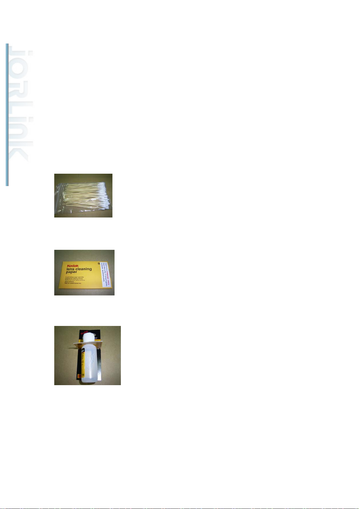
The following are three consumable items that you can purchase to clean the mirrors and
lenses.
1. Cotton buds ZZ01250A
2. Lens cleaning paper ZZ01249A
3. Lens cleaning solution ZZ01248A
41
Page 43
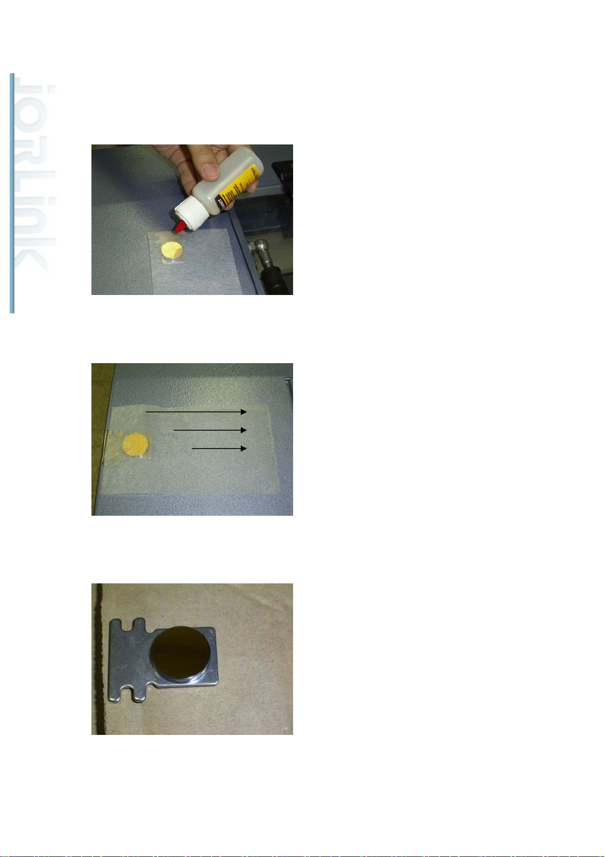
Cleaning the optical mirrors:
Distributed & Supported by: Jorlink USA, Inc. | Tel: (336) 288-1613 | [email protected] | www.JORLINK.com
43/60
Release the screws holding the mirrors in place. Place a piece of lens cleaning paper
and add a drop of lens cleaning solution.
Slowly pull the wetted paper from one side to another.
Make sure the lens is cleaned, dried and does not have any debris on the surface.
Cleaning the focusing lens:
First remove the lens from the pen carriage. To remove the focusing lens, release the
42
Page 44
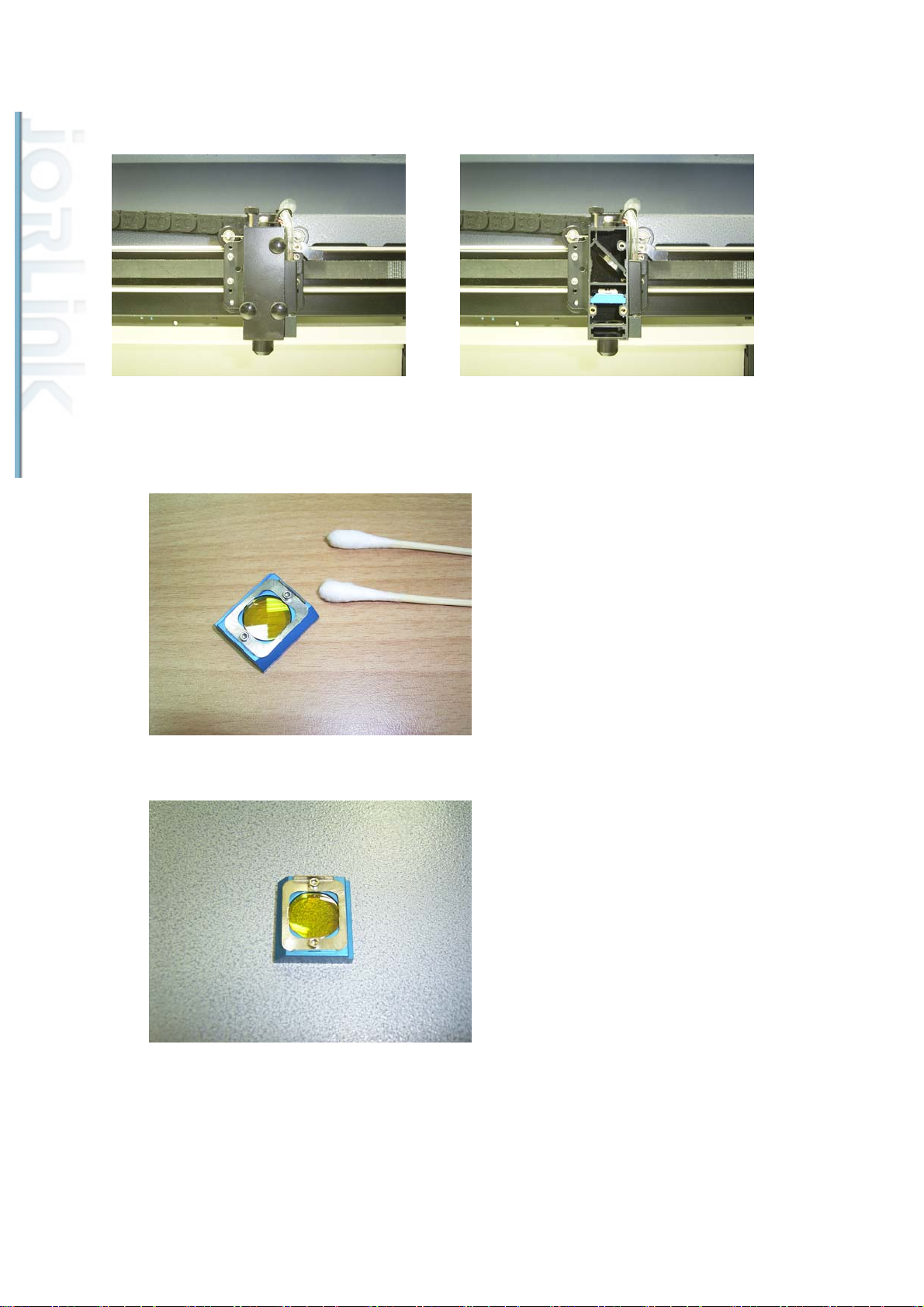
three screws on the pen carriage as shown below and locate the focusing lens in the pen
Distributed & Supported by: Jorlink USA, Inc. | Tel: (336) 288-1613 | [email protected] | www.JORLINK.com
44/60
carriage.
Apply a drop or two of the cleaning solution on a cotton bud and lightly clean the focusing lens.
Use a second cotton bud to dry or air dry the lens.
Make sure the lens is clean and dried before putting it back in the pen carriage unit.
2. Cleaning and protecting the X, Y rails:
In order to prevent the X and Y rails from chemical by-products produced when laser
passes through acrylic sheets, applying NSK, PS2 grease can prevent the rails from being
43
Page 45
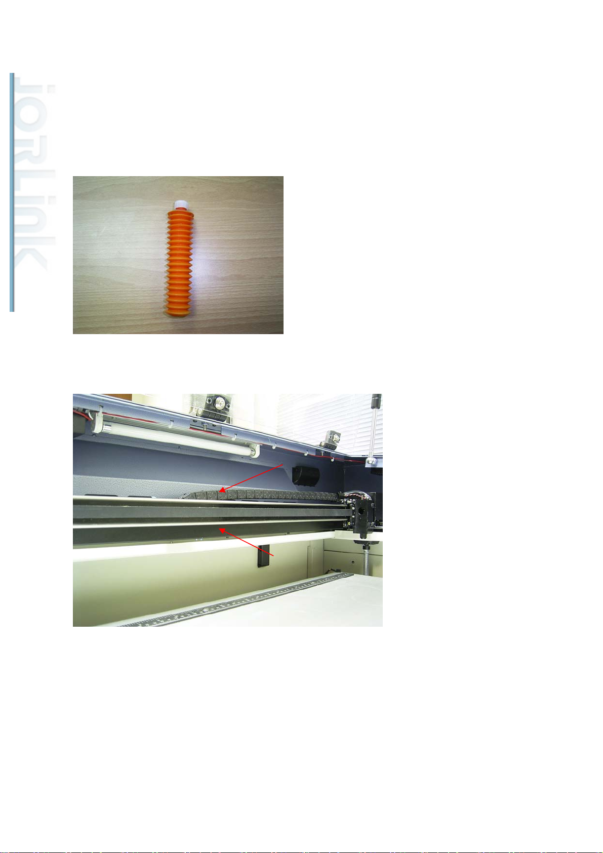
corroded.
Distributed & Supported by: Jorlink USA, Inc. | Tel: (336) 288-1613 | [email protected] | www.JORLINK.com
45/60
It is recommended that the X-rail should be cleaned daily or after each day’s operation.
The Y-rail requires the same type of cleaning and greasing about once a week. Use a piece of
non-abrasive cloth to swipe and clean the rails. Then apply a small amount of the PS2 grease
on to the rail and swipe it clean again.
PS2 grease MZ01417A
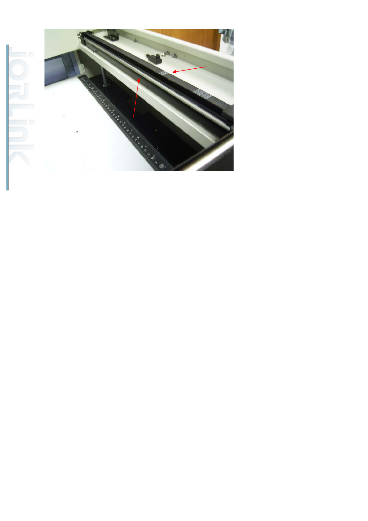
Please note that there are two rails on the X rail.
There are 2 rails on the Y-axis as well.
44
Page 46
Distributed & Supported by: Jorlink USA, Inc. | Tel: (336) 288-1613 | [email protected] | www.JORLINK.com
46/60
45
Page 47
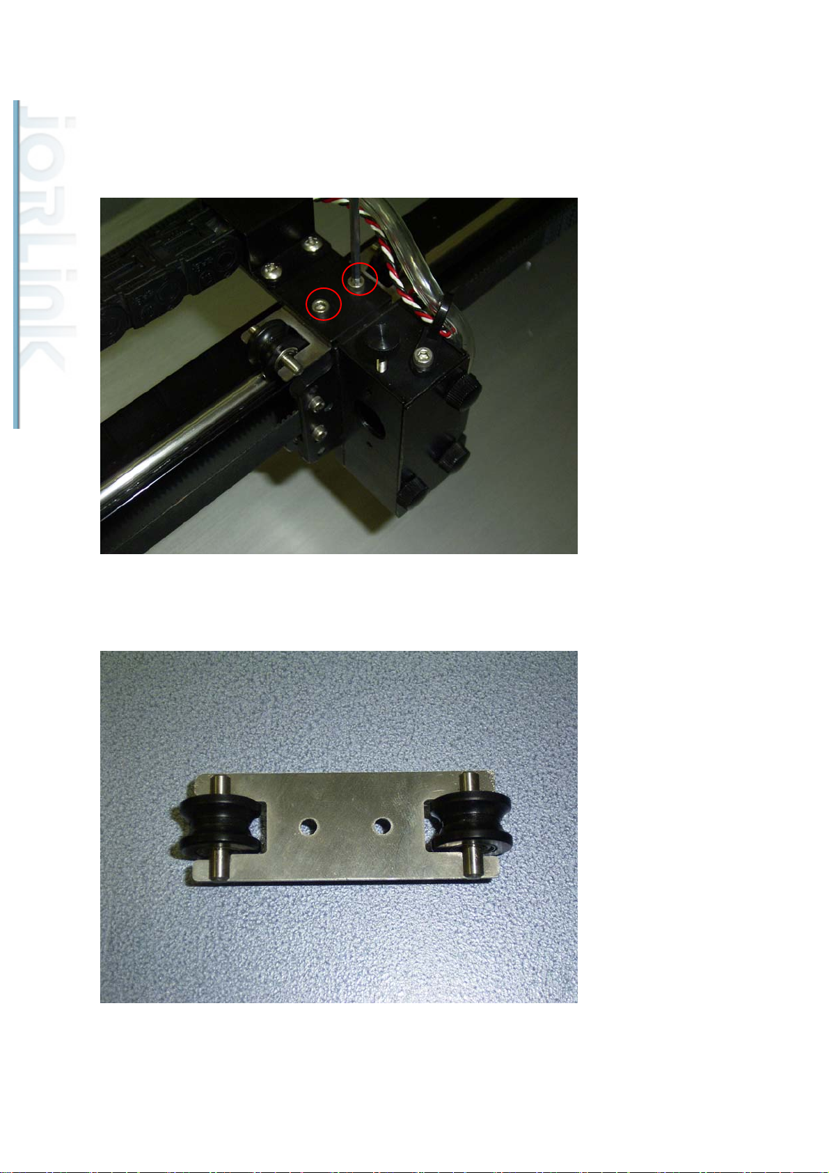
3. Changing the X rollers
Distributed & Supported by: Jorlink USA, Inc. | Tel: (336) 288-1613 | [email protected] | www.JORLINK.com
47/60
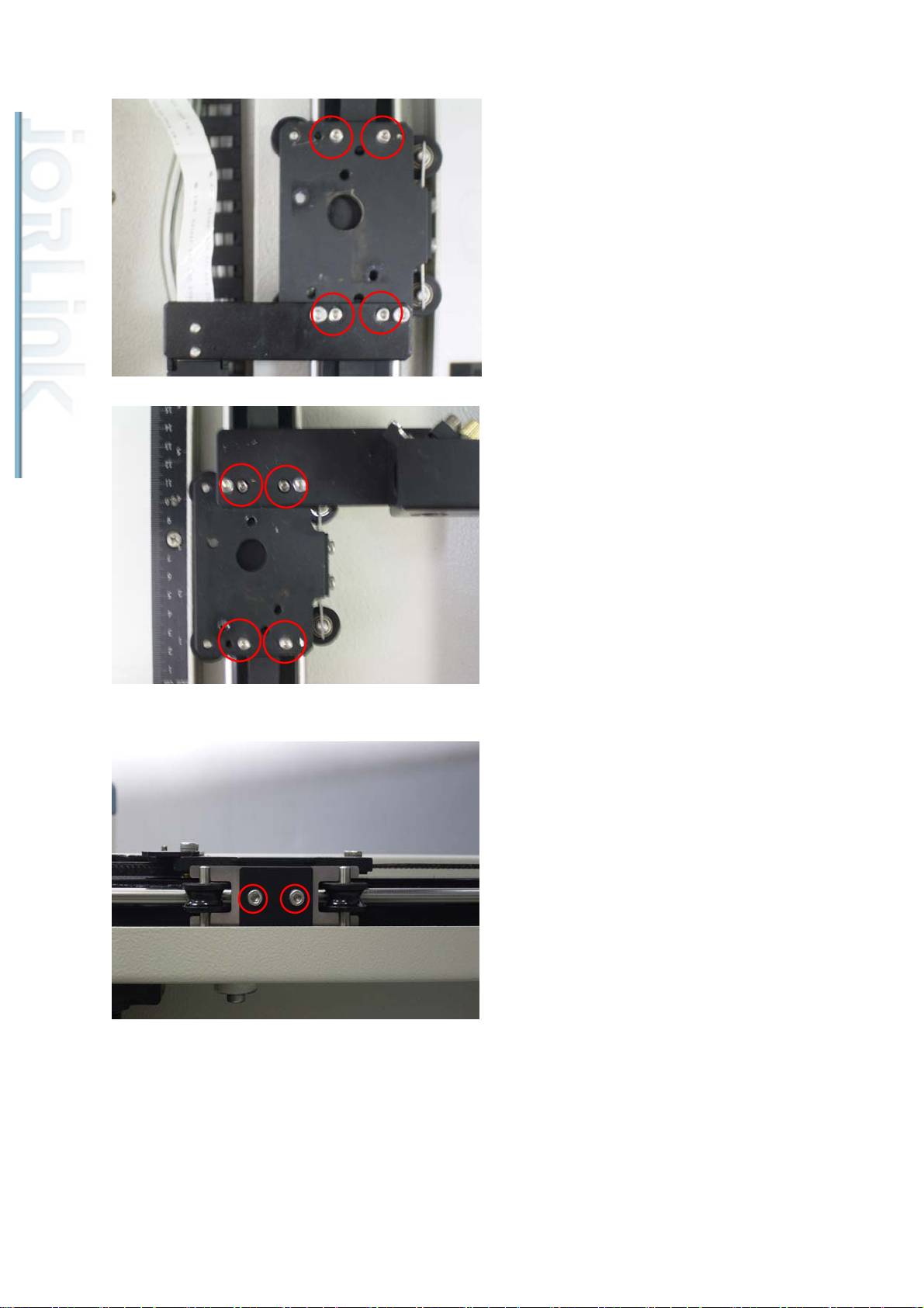
The estimated life of a set of rollers is about 500 working hours. To change rollers,
simply remove the hex bolts using a size 3 Allen key as shown below.
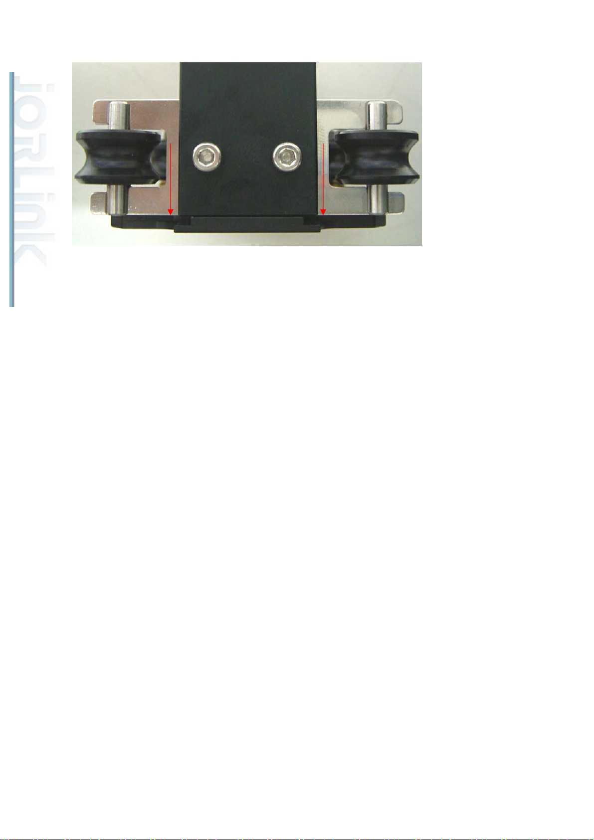
Notice that the roller has a wider side and a narrower side. The narrower side should be
closer to the pen carriage.
When installing the new rollers, make sure that we push the roller set towards the pen carriage
so that it is positioned against the lens carriage and then tighten the bolts.
46
Page 48
Distributed & Supported by: Jorlink USA, Inc. | Tel: (336) 288-1613 | [email protected] | www.JORLINK.com
48/60
47
Page 49
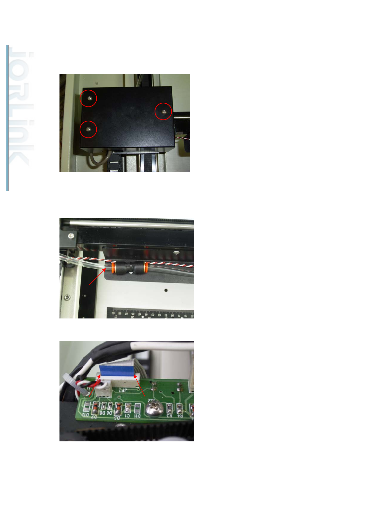
4. Exchanging the X-axis assembly
Distributed & Supported by: Jorlink USA, Inc. | Tel: (336) 288-1613 | [email protected] | www.JORLINK.com
49/60
Remove the screws shown below to remove the cover.
After removing the cover, disconnect the transparent air pipe and the X-motor flat cables
as shown.
Remove two hex bolts on each side of the X-axis.
48
Page 50
Distributed & Supported by: Jorlink USA, Inc. | Tel: (336) 288-1613 | [email protected] | www.JORLINK.com
50/60
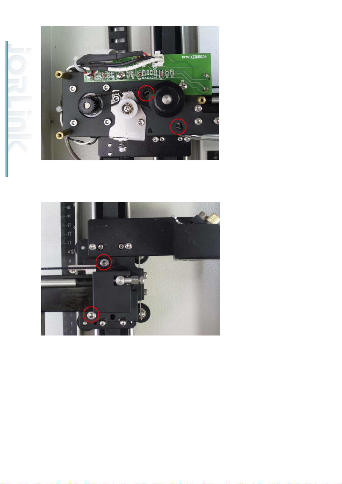
Then lift up the X-rail assembly to detach from the mounts.
5. Changing the Y rollers.
Detach the X-rail and remove the following screws to completely remove the Y roller
holders.
49
Page 51
Distributed & Supported by: Jorlink USA, Inc. | Tel: (336) 288-1613 | [email protected] | www.JORLINK.com
51/60
Unscrew the following screws to remove the side rollers.
50
Page 52

Chapter 4. Troubleshooting
Distributed & Supported by: Jorlink USA, Inc. | Tel: (336) 288-1613 | [email protected] | www.JORLINK.com
52/60
Section 1. Error messages
Error Message What does it mean? What to do?
"Laser Tube Error Laser
tube is over heat please
press any key to stop."
"HPGL Command Error
Get an odd number of
parameters please press any
key to stop"
"WARNING!
SmartGUARD fire alarm
system is activated, please
reboot machine"
"WARNING! Emergency
This means that the laser
tube’s temperature is too
high or the laser tube is
dead.
This means error has
occurred during the transfer
of data from driver to
firmware.
The SmartGuard fire alarm
system has been activated.
The Emergency button has
1. Turn off the machine to
allow the laser tube to
cool off.
2. Restart the machine to
see if the same message
shows.
1. Resend the data file.
1. Turn off the machine.
2. Check for fire or smoke.
3. Clear any hazards.
4. Turn on the machine.
1. Release the emergency
stop is activated, please free
the emergency stop to
continue next job"
"Please install the Auto
Focus pin first before
performing the auto
focusing or focus tuning"
" HPGL Command Error
Command: Address:
Please press any key to
stop"
been pushed down.
User is attempting to use
the Autofocus function
while the Autofocus pin is
not installed.
The firmware on the
machine and the driver is
not compatible.
button by turning it
clockwise.
1. Press “F1” to return
previous menu.
2. Install the autofocus
pin and to perform
Autofocus.
3.
1. Find out the firmware
and driver versions that
are being used.
2. Upgrade to the most
up-to-date firmware and
driver versions or use
compatible versions.
"Machine Moving Limit
reach upper limit switch
The Z-platform has reached
the top most limit.
51
1. Press any key to return
the previous page.
Page 53

please move opposite
Distributed & Supported by: Jorlink USA, Inc. | Tel: (336) 288-1613 | [email protected] | www.JORLINK.com
53/60
2. Check that the Z-limit
direction"
"PCL Command Error
Command: Address:
Please press any key to
stop"
"Error! Please check the
lens carriage position under
relative mode"
The firmware on the
machine and the application
driver is not compatible.
The output object is out of
the working area and cannot
be outputted.
switch sensor is
working properly.
3. Continue work or lower
the Z-platform if
necessary.
1. Find out the firmware
and driver versions that
are being used.
2. Upgrade to the most
up-to-date firmware and
driver versions or use
compatible versions.
1. Check that the output
object can be outputted
on the working area
"No Language Data Display
in English Please download
language data first"
The file that contains the
Language data is missing.
under the correct
position mode.
2. Adjust the pen carriage
to an open area. For e.g
Origin point for relative
mode or center of the
table for Center mode.
3. Restart the job.
1. Set the language back
to English.
2. Upload the missing
language file to the
machine.
3. Set the language mode
to the desired language
again.
"Storage total file size out
of 4M bytes. Please remove
some file"
The file being stored
exceeds the 4M size limit.
1. Reduce the size of file
to be stored to below
4M.
2. Save the file again.
52
Page 54

Distributed & Supported by: Jorlink USA, Inc. | Tel: (336) 288-1613 | [email protected] | www.JORLINK.com
54/60
"No Flash Memory. Please
check the device on
machine."
"X motor malfunction. For
service please inform your
local distributor"
The flash memory is not
detected.
X-motor failed or its related
components failed.
1. Make sure that the flash
memory is installed
properly.
2. Save file again.
1. Turn off the machine.
2. Move the lens carriage
from left to right by
hand freely to make
sure the rail is not
blocked.
3. Check for loosed
connections and bad
wirings.
4. Change the X-motor
PCB to see if the error
is with the PCB.
"Y motor malfunction. For
service please inform your
local distributor"
X-motor failed or its related
components failed.
5. Replace the X-motor
and check to see if
fixed.
6. If error remains after
the X-motor change,
replace the main board
as well.
1. Turn off the machine.
2. Move the lens carriage
from back and forth by
hand freely to make
sure the rail is not
blocked.
3. Check for loosed
connections and bad
wirings.
4. Change the Y-motor
PCB to see if the error
is with the PCB.
5. Replace the Y-motor
and check to see if
53
Page 55

fixed.
Distributed & Supported by: Jorlink USA, Inc. | Tel: (336) 288-1613 | [email protected] | www.JORLINK.com
55/60
6. If error remains after the
Y-motor change, replace
the main board as well.
"Z motor malfunction. For
service please inform your
local distributor"
Z-motor failed or its related
components failed.
1. Check that the
connections of the
wiring are not loosed or
damaged.
2. Replace the Z-motor.
54
Page 56
Section 2. Error lights
Distributed & Supported by: Jorlink USA, Inc. | Tel: (336) 288-1613 | [email protected] | www.JORLINK.com
56/60
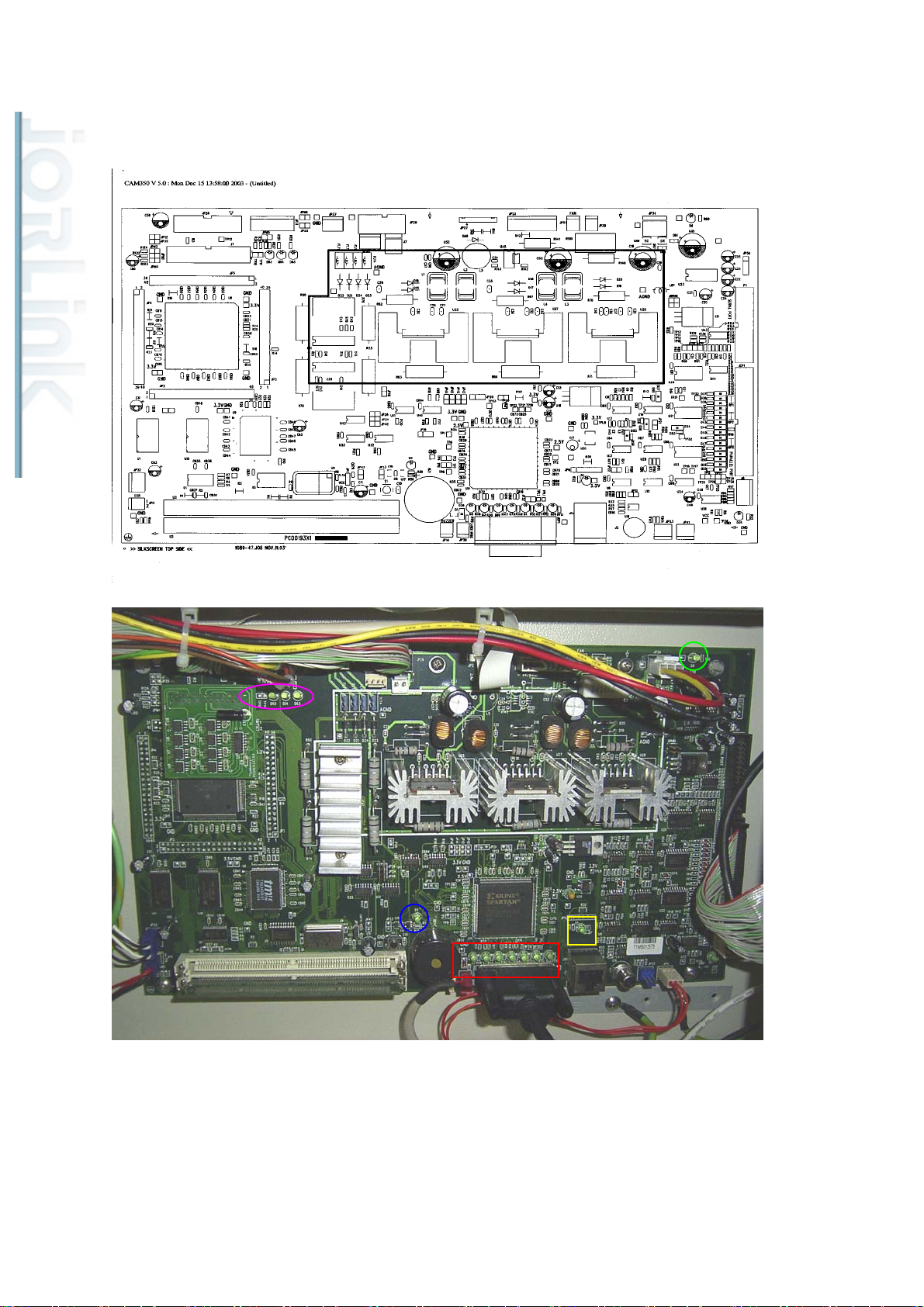
Identifying problems by looking at the lights on the mainboard.
The LED circled in green is the 5V light. This light should always be
“ON“ showing that there is a 5V supplied to the mainboard. Check that the power
supply next to the mainboard that provides the 5V power is working properly if it
is not “on”.
55
Page 57
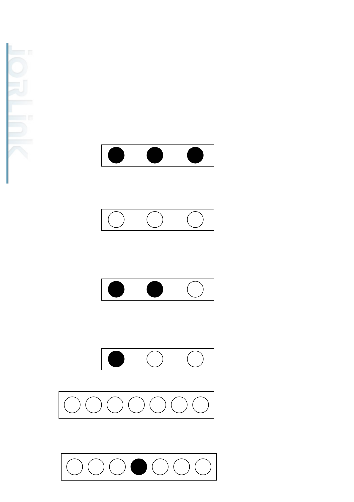
The LED circled in blue is the reset light. This light should only turn on when the
Distributed & Supported by: Jorlink USA, Inc. | Tel: (336) 288-1613 | [email protected] | www.JORLINK.com
57/60
reset button is hit. If it stays “on” all the time then the mainboard needs to be
changed.
The LED circled in yellow is the initialization light. This light turns on when the
machine is turned on. It will turn off after the initialization process. If it stays on,
then mainboard is damaged.
The LEDs circled in purple are the door sensor lights.
When all doors are closed, all three LEDs will stay “on”.
When the front door is open or front door sensors malfunctioning, all the LED
will turn off.
When the backdoor is open or the backdoor sensors are malfunctioning, the two
leftmost LEDs will turn “on”.
When the top cover is open or the top cover sensors are malfunctioning, the left
most LED turns to “on”.
The LEDs circled in red are the laser tube status lights.
For 50W & 100W models:
Under normal condition, the fourth light counting from the left will be “ON.”
However, the brightness of the LED depends on the power level used.
56
Page 58
Distributed & Supported by: Jorlink USA, Inc. | Tel: (336) 288-1613 | [email protected] | www.JORLINK.com
58/60
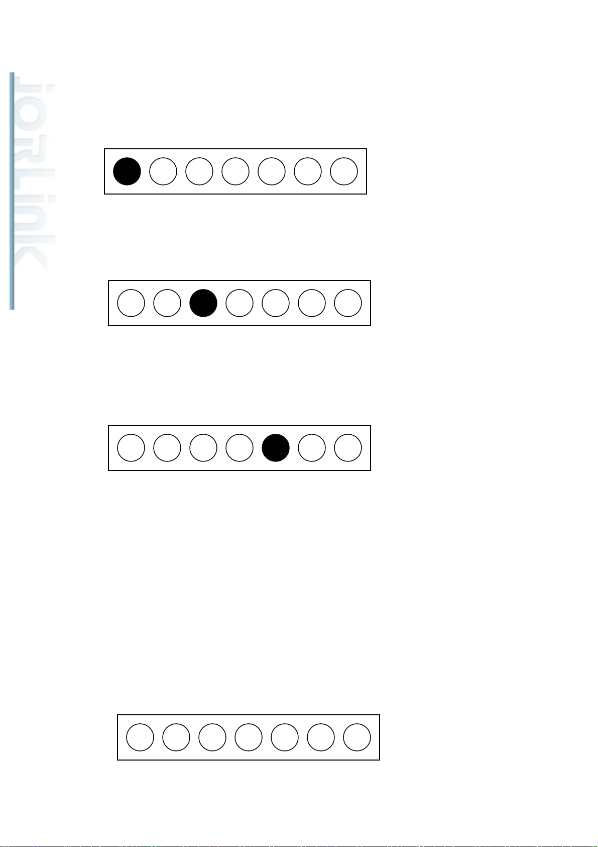
When the first LED from the left turns “ON”, check that the RF cable is
connected.
When the third LED from the left turns “ON”, either the laser head or the RF
cable is bad.
When the fifth LED from the left turns “ON”, the RF power supply has gone over
temperature.
For 30W models:
Only the two right most LEDs are used for 30W models. Under normal
condition, all LEDs will not turn “ON”.
57
Page 59
Distributed & Supported by: Jorlink USA, Inc. | Tel: (336) 288-1613 | [email protected] | www.JORLINK.com
59/60
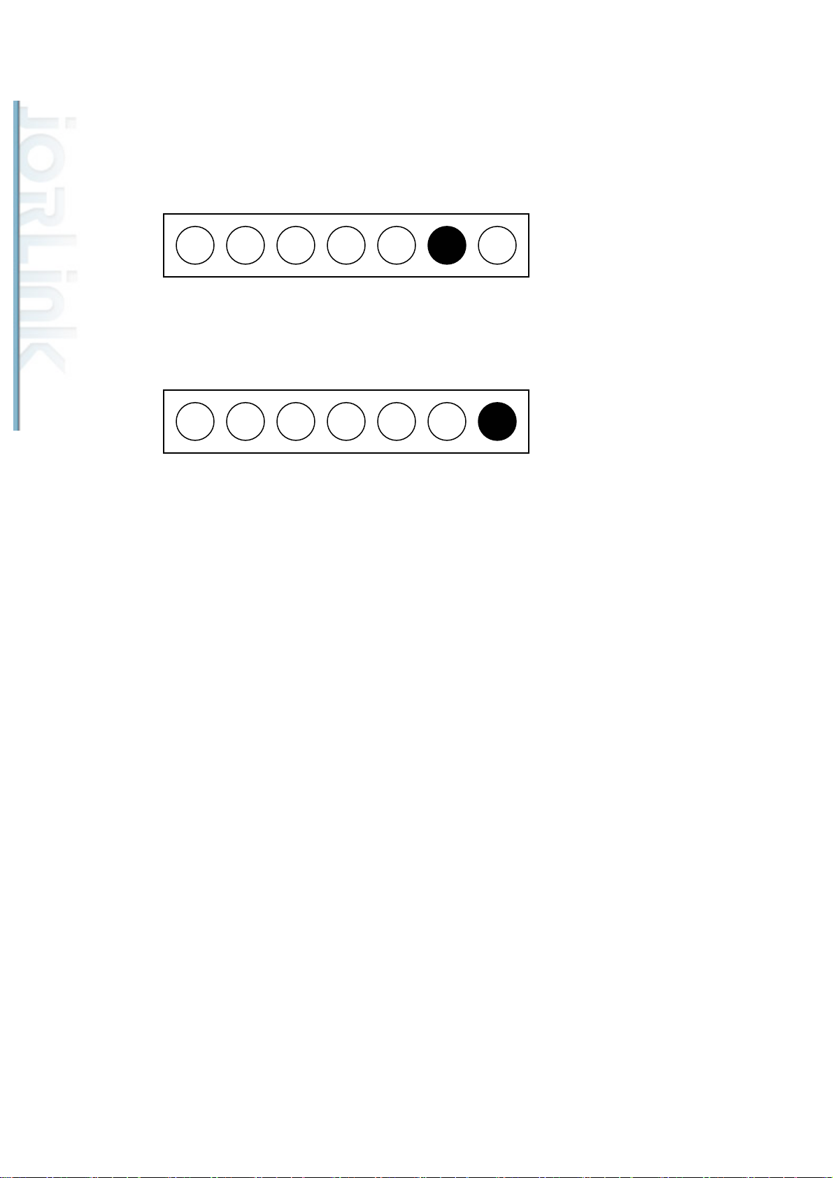
During initialization, the sixth LED from the left will turn “on” by default. The
LED will turn “off” after the initialization meaning that the laser is ready to fire.
However, if the LED stays on afterwards, that means the laser source is
malfunctioning.
When the last LED from the left turns “ON”, the incoming voltage to the laser
source is incorrect. Check that the output voltage to the laser source is correct.
Note: If the electrical circuit in the laser source has been damaged then the
signals shown may not reflect the exact problem.
Setting tickle pulse on Spirit machines equipped with Synrad laser sources.
By nature, Synrad laser sources require a tickle pulse to keep the laser ready
for firing. The tickle pulse signal required depends on the individual laser tube.
The usual setting is at 5k, however, it may be required to adjust the tickle pulse
rate. If the laser is too weak, we can set it to 7k and if the laser is bleeding, then
we can set it to 3k.
Hold the “down arrow key” when turning on the machine until “Laser Tube
Model Number” shows on the display. Wait till the lens carriage comes to a
stop. Press the Enter key to get to the Model Number selection page. Select
the corresponding laser tube model from this page. Press F4 and then the
58
Page 60

Start/Stop key to save and restart the machine.
Distributed & Supported by: Jorlink USA, Inc. | Tel: (336) 288-1613 | [email protected] | www.JORLINK.com
60/60
59
 Loading...