

Page 1

OPTIMIST
OPTIMIST
Rigging Manual
1. Nautical Terminology
2. Contents of Packaging
3. Attaching the Mainsheet Blocks
4. Attaching the Sail
5. Rigging the Outhaul
6. Stepping the Mast
7. Mast Tie-in
8. Boom Retainer
9. Assembling the Vang
10. Attaching the Painter
11. Rigging the Sprit Halyard
12. Attaching the Sprit
13. Rigging the Mainsheet Bridle
14. Rigging the Mainsheet Bridle Safety
15. Rigging the Mainsheet
16. Rigging the Rudder
17. Rigging the Daggerboard Retainers
18. Attaching the Hiking Strap Lifter
19. De-rigging
20. Sail Care
Page 2
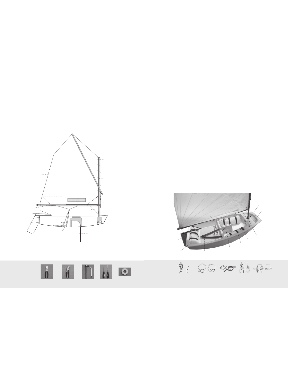
Port: Left side of t he boat when looking for ward
Starboard: Right side of t he boat when looking for ward
Gunwale: Upper edg e of a boat’s side
Leeward: Direction away from t he wind
Windward: Direction from wh ich the wind is comi ng
1. Nautical Terminology
Useful
knots
to know
CLEAT CLOVE HITCHBOWLINESQUARE KNOTFIGUR E 8 OR
STOPPER KNOT
Optimist Rigging Instructions
Congratu lations on the purchase of your new L aserPerformance O ptimist! We suggest th at you
read through this guid e to better familiarize yoursel f with the par ts and rigging of your new
boat. If you have any questions please cont act your dealer or call LaserPerforma nce’s customer
service department, contact information can be found on t he back cover of this guide.
Head of Sail
Sprit
Sail
Leach
Lu
Mast
Sail Tie
Foot of the Sa il
Clew Tack
Boom
Outhaul
Tiller with Extension
Rudder Mainsheet
Halyard
Vang
Daggerboard
Mainsheet Blocks
Rudder
Stern
Mainsheet
Mainsheet Bridle
Hiking Strap
Daggerboard T runk
Airbag Straps
Airbag
Mast wart
Bow
Mast Collar
1. Glossary
Aft: Back of the boat
Backstay: Support at the b ack of the boat to the t op of the mast
used to control t he mast bend, an d support the ma st.
Bow: Front of the bo at
Burgee: Wind indic ator, usually a fl ag
Batten: A thin sti en ing strip in th e sail to suppor t the leach
Boom: A spar at the foo t of the sail
Cleat: A fi tting use d for holding/sec uring ropes
Clew: Back lower cor ner of a sail
Cunningham: An eye in the sa il above the tac k of the sail
Foot: Bottom of the s ail
Forestay: e wire suppor ting the ma st at the bow of the boat
Gennaker: Isometri c sail hoisted whe n sailing dow nwind
Gennaker Pole: e pole that ext ends from the bow to fl y the gennaker
sail.
Gunwale: e outermost e dge of the boat
Gudgeon: Fitting on t he transom a nd rudder use d to hang rudde r
Head: Top of sail
Halyard: A rope or wire u sed to lower or hoist sa ils
Jib: Front sail
Jib Sheet: Control rope for t he jib
Leech: Trail ing edge of the sa il
Lu : e front edge of the sa il
Mast Heel: e fi tting at t he base of the mas t
Mast step: e fi tting on t he boat where the ma st heel is located
Spreaders: Metal str uts placed in pa irs to support t he mast
sideways and co ntrol the bend in th e mast.
Stern: Back of the bo at
Stem fi tting: Sta inless fi tting a t the bow to which the for estay
attaches.
Tack: Forward lowe r corner of the sai l
Traveller: e track that r uns side to side t hat controls the m ainsail
sideways in th e boat. Used in conjunc tion with the ma insheet.
Vang: Otherwi se known as th e kicking str ap.
Here is a list o f tools
needed to assemble
your new Opt imist:
WRENCHES
ELECTRICAL
TAPE
SCREWDRIVERSUTILITY KNIFEPLIERS
Page 3
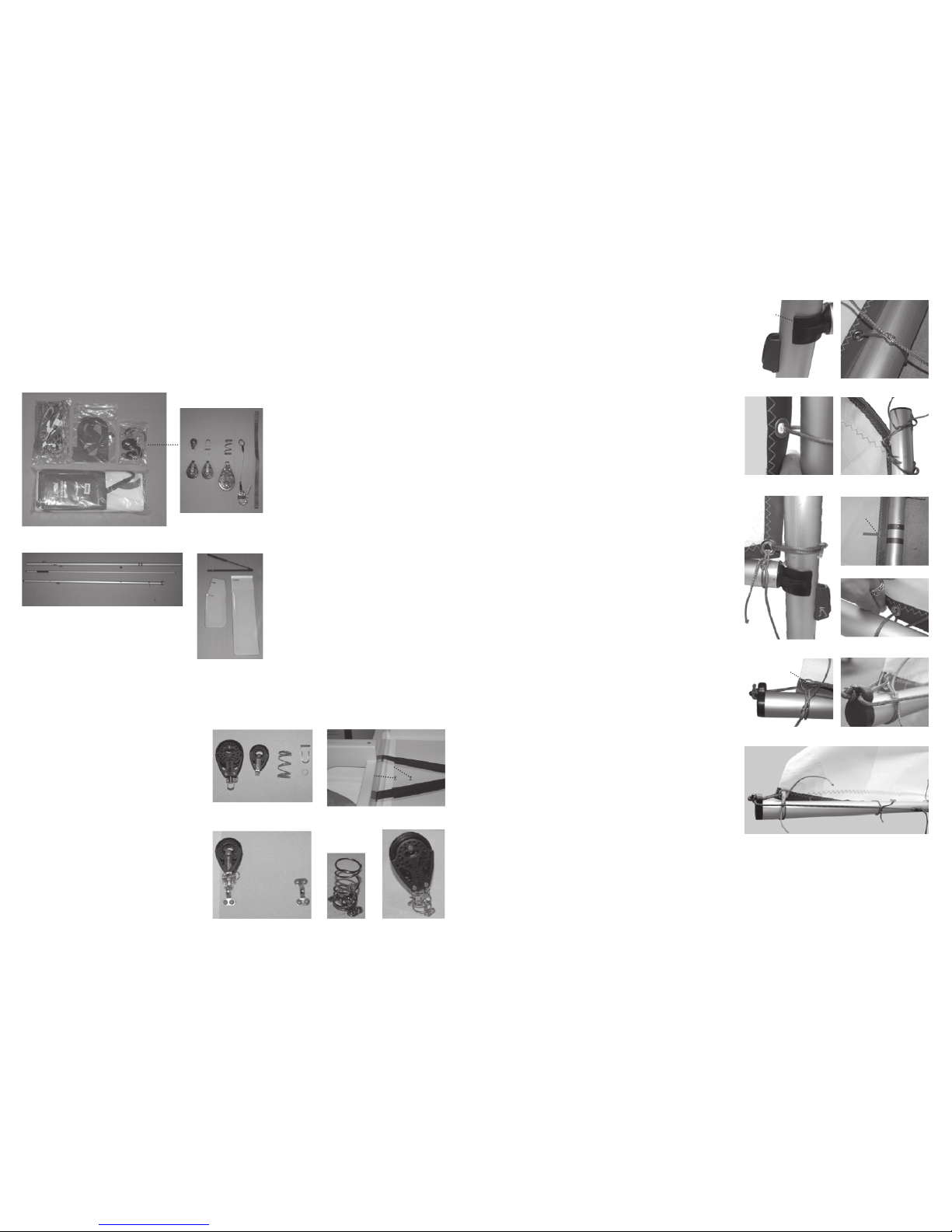
2. Contents of Packaging
fi gure 12
Your new Las erPerforma nce Optimist w ill come with t hree
boxes. One box for t he spar set, one for the bl ades and one for
the deliver y kit contain ing the sail, blo ck and lines.
Use caution wh ile opening the b oxes to avoid damagi ng the
contents. Be su re not to cut into the pac kaging insid e of the box.
2.
3.
4.
1.
2.
3. 4. 6.
5.
7.
1.
Locate t he box labeled del ivery kit (fi gure 1).
Inside you w ill fi nd:
1. Line bag
2. Country sa il letters/numb ers
3. Hardware
4. Sail wit h sail bag and dig ital 8
sail numbers
Contents of bag # 3 (fi gure 2)
1. Micro bul let block
2. Carbo bloc k with becket (2)
3. Shackle, pi n and ring
4. Compression spr ing
5. Mainshe et ratchet block
6. Mains heet snap shackle w ith
strap and r ing
7. Daggerboard retainer strap
Locate t he box containing t he spars.
Inside you w ill fi nd (fi gure 3)
1. Mast
2. Sprit
3. Boom
Be sure to re move all of the packa ging
(plast ic, bubble wrap, zip ties) before
continui ng to rig your Opti mist. Use
caution when re moving the zip ties s o you
do not to scrat ch the spars.
Locate t he box containing t he blades
(Figu re 4). Inside you will fi nd:
1. Tille r with extension
2. Rudder
3. Daggerboa rd
fi gure 1
fi gure 2
1.
2.
3.
fi gure 3
fi gure 4
1.
2. 3.
3. Attaching the
Mainsheet Blocks:
1. Locate the b ag from the deliver y kit
contain ing the mainshe et blocks. Remove
the mai nsheet ratchet bloc ks, compression
spring, 1 ca rbo block and the sh ackle, pin
and ring (fi gure 5).
2. ere are two eye straps located on th e
cockpit fl oor, aft of the daggerb oard thwart
(fi gure 6). With the shack le pin and ring,
attach t he carbo block to the fo rward most
eyestrap (fi gure 7).
3. Remove the sha ckle pin and rin g from the
mainsh eet ratchet block. L oop the shackle
beneath th e aft eyestrap and pl ace the
compression s pring over it (fi gure 8).
4. While compr essing the spri ng, place the
mainsh eet ratchet block at the t op of the
spring a nd align the hole i n the bottom
of the block w ith the holes in the sha ckle.
Secur e the ratchet block to t he shackle
with the pi n and ring (fi gure 9).
fi gure 5
fi gure 6
fi gure 7 fi gure 8 fi gure 9
4. Attaching the Sail:
1. Retrieve t he mast, boom, sai l, corner ties and s ail ties.
2. Attach the b oom jaw to the mast right ab ove the sprit
halyard c leat (fi gu re 10). When laying t he mast and boom
down, be su re that the area is fr ee of sharp objects t hat
could da mage the sail.
3. Unwrap the sa il. Lay the sail dow n over the mast and
boom, ali gning the mast w ith the lu of the sail and the
boom with t he foot of the sail.
4. Locate the s ail ties. Star ting at the mast, lo op the ties
around t he mast and throu gh the grommet in th e sail.
Secur e with a square knot (fi gur e 11). Tie the sail ti es
tight enoug h that you can slip one fi nger between the
sail an d the mast (fi gure 12).
5. Locate the co rner ties. Star ting at the top of the ma st,
lead one of the cor ner ties throug h the top eyestrap the n
through t he top grommet in the s ail. Wrap the corne r
tie arou nd twice before sec uring with a sq uare knot
(fi gure 13). Repeat for lower eyest rap.
6. Using two mor e corner ties, secu re the tack of the sa il
to the boom a nd the mast (fi gure 14).
7. Be su re to adjust the corner t ies in order to get the re d
mark on the lu of the sai l to fi t betwe en the two blue
stripes o n the mast (fi gure 15).
8. Continue ty ing the sail t ies onto the boom. Tie th e sail
ties tight e nough that you can pla ce two fi ngers between
the boom a nd the sail (fi gure 16).
9. Tie o the last corne r tie to the clew of the sa il.
5. Rigging the Outhaul:
1. Locate the o uthaul line. Tie a st opper knot in one end.
Lead the fr ee end of the line thr ough the port hole in t he
boom end cap (fi gure 17).
2. Continue the l ine through the c lew grommet and bac k
through t he open hole in the boom c ap (fi gure 18).
3. Lead the li ne forward alon g the starboard s ide of the
boom and t hrough the v-cleat (fi gure 19). Cleat o and tie
a stopper kn ot in the end of the line.
fi gure 10 fi gure 11
fi gure 13
Boom Jaw
Spirit Halyard
Cleat
Mainsheet Block
Carbo Block
fi gure 14 fi gure 16
fi gure 15
fi gure 17 fi g ure 18
fi gure 19
Rail Sail
Line
Lines on
the Mast
Grommet
Page 4
fi gure 30
fi gure 20
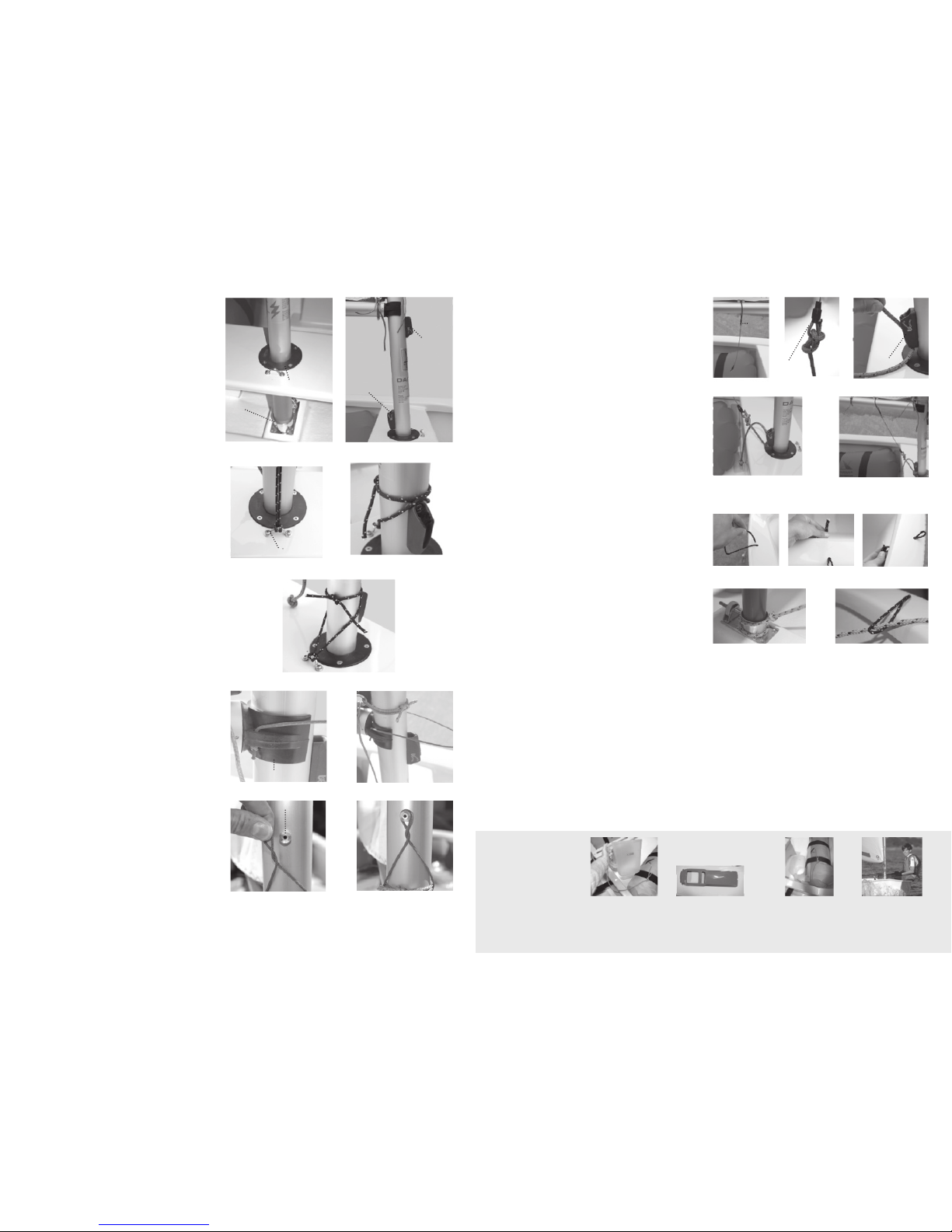
6. Stepping the Mast:
1. Lift the m ast with sail a nd boom attached.
2. Align t he mast butt over the m ast collar.
Gently sli de the mast throu gh the thwart an d
into the met al mast step (fi gure 20).
3. Make sure t hat the sprit halya rd cleat is
facing t he bow while the cleat fo r the vang
cleat is fac ing the stern (fi gure 21).
7. M a st T ie- in:
1. Locate th e mast tie-in li ne. e ma st tie-in
eyestrap i s located on the thwa rt forward of the
mast (fi gure 22).
2. Tie a luggage k not with the mast t ie-in line
around t he eyestrap (fi gure 22).
3. Lead the end s of the line around t he mast.
Cross the p ort line over the st arboard line r ight
above the va ng cleat (fi gure 23).
4. Lead the two e nds back around to t he front
of the mast a nd secure with a s quare knot
(fi gure 24).
8. Boom Retainer:
1. Locate bo om retaining l ine from the line bag.
Tie a stopp er knot in one end of the li ne. Lead
the line up t hrough the star board hole in the
boom jaw (fi gure 25).
2. Lead the fre e end of the line arou nd to the port
side hole in th e boom jaw. read the l ine down
through t he hole and secure w ith a stopper knot
(fi gure 26).
3. Located jus t above the boom jaw, centered on
the mast i s the mast retai ner peg (fi gure 27).
4. Twist t he boom retainer l ine until the li ne is
taught when pla ced over the peg (fi gure 28).
fi gure 21
fi gure 22 fi gure 23
fi gure 24
fi gure 25 fi gure 26
fi gure 27 fi gu re 28
Here are a few sa fety
products th at we
suggest you h ave to
keep you safe ! Refer
to the Opti mist class
rules as mo st of these
items are requ ired
for racing.
MAK E SURE YOUR
BAIL ER AND PADDLE A RE
SECUR ED INTO T HE BOAT
AND OU T OF YOUR WAY.
ALWAYS WEAR
YOUR L IFEJAC KET!
DON’T R ELY ON THE
BREE ZE, HAVE A
PADDLE.
TO KEE P WATER OUT
OF THE BOAT, HAVE
A BAIL ER HANDY.
9. Assembling the Vang:
1. Locate the v ang wire attac hed to the
forwar d boom button (Fig ure 29).
2. Retrieve t he vang line from t he line bag.
With a bowli ne, tie the vang line t o the thimble
located at t he end of the vang wire ( Figure 30).
3. Lead the va ng line up through t he clam cleat
located on t he mast just above the t hwart
(Figure 31).
4. Cleat o . Tie a stopper knot i n the end of the
vang li ne (Figure 32).
10. Attaching the Painter:
1. Locate th e bow loop and painter l ine from the
line bag. T ake the bow loop lin e and thread both
ends down t hrough the sma ll hole on the topside
of the bow (Fi gure 33 & 34).
2. Tie o the two ends the bow l oop with a
square k not (Figure 35).
3. Pull up on t he bow loop so that the sq uare
knot is snugly s ecured beneath t he rail of
the bow.
4. Wrap the paint er line around th e mast step,
undern eath the adjustor bolt, and s ecure it with
a bowline (F igure 36). Lead the l ine up through
the bow loop (F igure 37). Place the re mainder of
the paint er in the bow of the boat.
fi gure 29
fi gure 31
fi gure 32 Completed Vang
fi gure 33 fi gure 34 fi gure 35
fi gure 36 fi g ure 37
wart
Mast Collar
Mast Step
Sprit
Halyard
Cleat
Vang
Cleat
Bow
Eyestrap
Bow Stern
Boom Jaw
Mast Peg
Vang
Cleat
imble
Clam
Cleat
Page 5

11. Rigging the Sprit
Halyard:
1. Locate th e upper and lower sprit
halyar d line from the line ba g.
Retrie ve the micro singl e block from
the deliver y kit.
2. Tie a bowlin e in one end of the
upper sprit h alyard. Maki ng sure to
leave a very sm all loop that ca n then
be placed onto t he end of the sprit
pole (fi gure 38).
3. Run the free e nd of the line
through t he micro single blo ck that
is attach ed to the middle of the m ast
(fi gure 39).
4. Tie a bowl ine to the micro sin gle
block wit h the free end of the upper
sprit haly ard line (fi gure 40).
5. With the lower spr it halyard
line tie a b owline to the top of th e
halyar d cleat located on the m ast
below the b oom connection (fi gure 41).
6. Lead the li ne through the mic ro
single blo ck and then back th rough
the cleat to s ecure (fi gure 42).
7. Place a stopper kn ot in the tail of
the lower ha lyard line.
12. Attaching
the Sprit:
e sprit ha s two di er ing ends. One
end has a r ubber sleeve coverin g a
section of t he aluminum. is end
will at tach to the sprit ha lyard as the
rubber is u sed to reduce the cha fe
against the mast.
1. Locate the s prit loop at the head of
the sai l (fi gure 43).
2. Place the spr it end without the
rubber sl eeve into the loop in the
head of the sa il (fi gure 44).
3. Place the opp osite end of the sprit
into the sm all loop created b y the
bowline in t he upper sprit haly ard.
Pull on t he lower sprit halya rd to
raise t he top of the sail (fi gure 45).
Attached
Micro Single
Block
Micro Single
Block
fi gure 39
fi gure 42
fi gure 41
fi gure 40
fi gure 38
fi gure 43
fi gure 44
fi gure 45
13. Rigging the
Mainsheet Bridle:
1. Locate th e mainsheet snap sh ackle with
penna nt from the delivery k it and the
mainsh eet bridle line f rom the line bag
(fi gure 46).
2. Find the cent er of the mainsheet b ridle
line and at t he midpoint tie a lugga ge knot
onto the rin g of the snap shackle p ennant
(fi gure 47).
3. Located on t he topside of the boom, you
will fi nd two bo om buttons (fi gure 48).
Take one end of t he mainsheet br idle
line and l ead it through one of the bo om
buttons, aro und the boom and sec ure with
a bowline (fi gure 49). Repe at with the free
end of the lin e at the other boom button
(fi gure 50), tying the l ine as tight as
possible. Ma ke sure the mai nsheet
shackl e is suspended even ly between the
two boom but tons (fi gu re 51) and that the
bridle r uns beneath the out haul line.
14. Rigging the Mainsheet
Bridle Safety:
1. Locate th e mainsheet brid le safety line
from the li ne bag. e m ainsheet brid le
safety i s used to secure t he mainsheet
bridle c loser to the boom. Ta ke the safety
line and l ead it around the boom a nd
through t he ring of the snap sha ckle
penna nt twice. Secure w ith a square knot
(fi gure 52).
Safety Issue: e mainshe et bridle sh ould not span
from the boo m further th an 100 mm (~ 4”). A quick
guide wou ld be the width o f three fi ngers (fi gure
53). Refer to th e Optimis t class rules fo r complete
details www.usoda.org.
15. Rigging the
Mainsheet:
1. Locate th e carbo block from th e delivery
kit. e hole locate d in the center of the
block is th e becket
(fi gure 54).
2. Retrieve t he mainsheet l ine from the
line bag. L ead one end of the main sheet
through the becket (fi gu re 55) and secure
the end wit h a stopper knot (fi gure 56).
fi gure 46 fi gure 47 fi gure 48 fi gure 49
fi gure 51fi gure 50
fi gure 52 fi gure 53
fi gure 54 fi gure 55 fi gure 56
Rubber
Chafe Sleeve
Mast Peg
Outhaul Line Mainsheet Bridle
Mainsheet Carbo
Block
Becket
Page 6
To lift
tiller up
fi gure 69
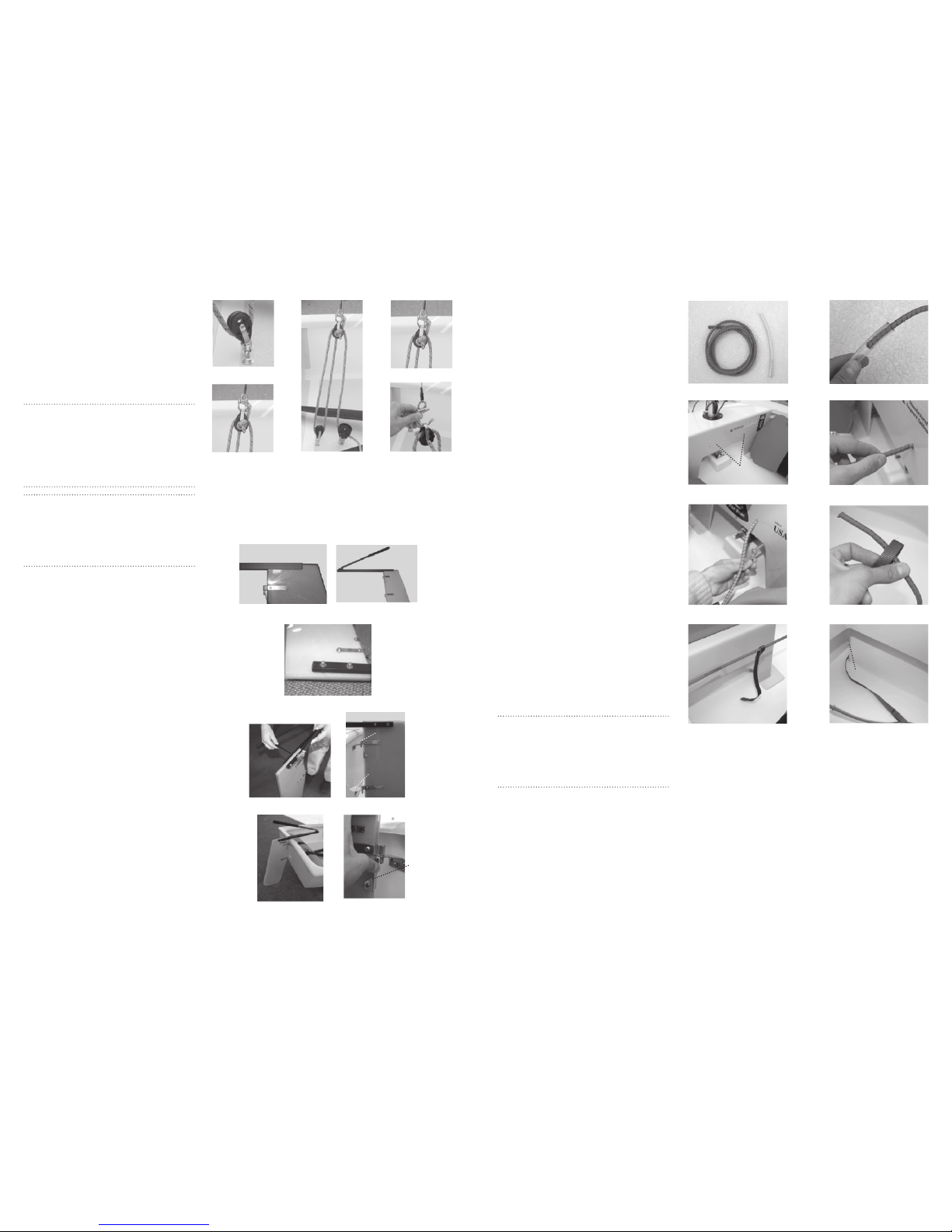
15. Rigging the Mainsheet
Continued :
3. Lead the ma insheet from the be cket
down to th e forward main sheet block
on the cock pit fl oor (fi gure 57). Lea d the line
back up thr ough the carbo bloc k (fi gure 58).
Continue the l ine down throu gh the mainsheet ratch et block (fi gure 59).
Note: Make su re while pullin g the mainshe et the
block mak es a ratchetin g noise. If the bl ock does not
make a ratche t sound, one o f two things co uld be the
problem. F irst try r unning the mai nsheet thr ough the
block the op posite way. If thi s does not work, l ocate
the lever o n the mainshe et block and s witch it to the
ratchet po sition.
Safety: e mains heet is conn ected to the b ridle by
a snap shack le confi guration. e snap shack le is
provide d as a safety de vice that ca n quickly be di sconnected b y pulling on th e shackle pin to r elease the
shackle open (fi gu res 60 & 61). Press the bot tom of the
shackle ba ck over the pin t o close.
16. Rigging the Rudder:
1. Locate th e rudder and til ler from the
blade del ivery box. e tille r screws and
washers sho uld already be att ached to the
tille r. Remove the s crews. Align the t wo
holes in the t iller with the t wo holes in the
top of the ru dder (fi gure 62). Make sure that
the til ler extension fac es upward
(fi gure 63).
2. Place one was her over each hole and
insert the screw (fi g ure 64). On the
opposite sid e place one washer over eac h
screw. Using plie rs or a crescent wrenc h,
secure t he nylon lock nuts over the s crews
(fi gure 65). e lock nut s should be
tightened s o that the tille r is snug.
Do not over tig hten!
3. Align t he pintles on the ru dder over the
holes in the g udgeons on the boat (F igure
66). Press dow n making sure t he pintles are
locked in pl ace (fi gure 67).
4. To remove the rud der, press in the
retain ing clip while pu lling strai ght up on
the rudd er (fi gur e 68). Once the upper pintle
clears t he retaining c lip the rudder w ill be
released.
fi gure 57
fi gure 58 fi gure 59
fi gure 60
fi gure 61
fi gure 62 fi gure 63
fi gure 64
fi gure 65 fi gure 66
fi gure 67 fi gure 68
17. Rigging the Daggerboard
Retainers:
1. Locate th e daggerboard st rap,
shockcord a nd plastic tubing f rom the
line bag (fi gure 69). Place o ne end of the
shockcord int o the tubing and sli de to the
center of the sho ckcord (fi gure 70).
2. Locate the t wo holes in the mast t hwart
(fi gure 71). Take one end of t he shockcord
and thre ad it into the starboa rd hole (fi gure
72). Tie a stopp er knot in the shockcor d on
the back side of the thwart (fi gure 73). Make
sure that t he knot is secure s o that when
the shockco rd is extended the k not does not
slip loose.
3. Slide the fre e end of the shockcord
into one end of the d aggerboard st rap
(fi gure 74 & 75).
4. Lead the da ggerboard stra p around the
backsid e of the daggerboar d trunk betwe en
the space c reated by the dagge rboard trun k
and cockp it fl oor (fi gure 76).
5. Continue the fr ee end of the shockcord
through t he other side of the dag gerboard
strap. Lead t he shockcord back up to t he
mast thw art and secur e the free end in the
port hole. Aga in make sure th at the knot is
tight so th at it will not release wh ile under
load.
6. Retri eve the daggerboa rd from the
deliver y kit. Locate the hole in t he handle
of the daggerboard. is side should f ace
towards t he bow.
Note: Do not pl ace the dagge rboard into the d aggerboard s lot while the bo at is on land. Do ing such
will dama ge the botto m of the board. Onl y place the
dagger board into the tr unk when the boat i s in the
water. e daggerboard sho uld be lowered g radually
as you sai l into deeper wa ter.
fi gure 70
fi gure 72fi gure 71
fi gure 73
fi gure 75 fi gure 76
fi gure 74
Pintle
Gudgeon
Rudder
Retaining
Clip
Daggerboard Retainer
Holes
Aft Edge of
Daggerboard T runk
Page 7
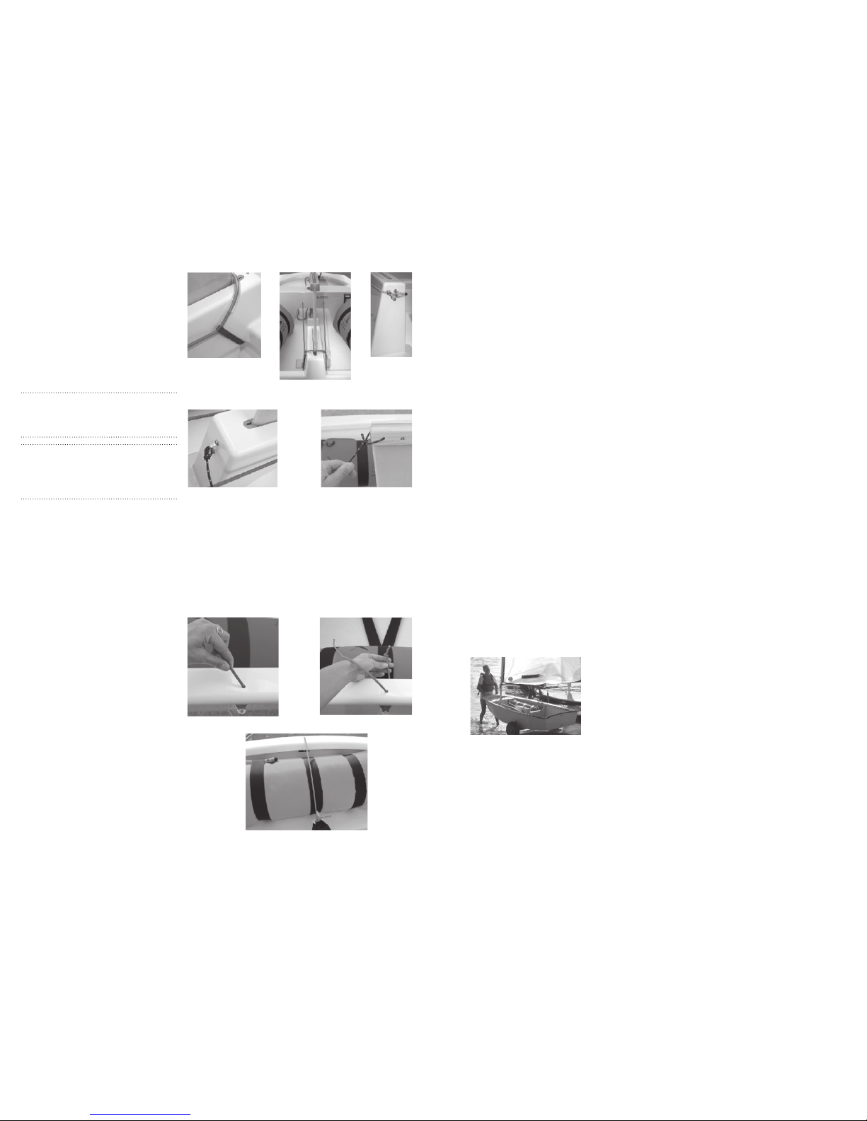
fi gure 77
fi gure 79
17. Rigging the Daggerboard
Retainers Continued:
7. When t he daggerboar d is inserted into
the tru nk, take the shock cord with the
plastic t ubing and bring it t o the aft edge
of the board (fi gure 7 7). As the daggerboa rd
is lifte d the compression of the sho ckcord
again st the aft edge wi ll keep the board
in the desi red lifted posit ion without the
board sl ipping back into the tr unk.
Note: Make su re that the plas tic tubing i s against
the aft ed ge of the board. W ithout the pla stic tubi ng
the shock cord will wear ou t faster due to t he frictio n
on the sharp e dge of the board .
Option: e daggerboard sh ockcord end s can be led
to the eye strap on the fro nt of the dagger board trunk
instea d of the holes in th e mast thwar t. is option
it allows for th e front of the cock pit to remain cl ear
(fi gure 78).
8. Retrie ve the daggerboa rd safety line fro m
the line b ag. Tie one end of the line t o the
eyestrap lo cated on the front side of th e daggerboard t runk with a bo wline (fi gure 79).
9. Lead the fr ee end of the line up to
the dagg erboard handl e. read the
line th rough the hole at the front of the
daggerb oard. Secure wit h a bowline
(Figure 80).
18. Attaching the Hiking
Strap Lifter:
1. Locate th e hiking strap l ifter shockcord
from the li ne bag.
2. Take one end of t he hiking strap sh ockcord and lead it t hrough the hole locat ed in
the ster n rail of the boat. (Fig ure 82)
3. Tie a stopper k not in the end of the
shockcord th at will rest bene ath the rail
of the boat. (fi gure 83)
4. Draw the lin e over the airbag and s ecure
it to the hik ing strap. It is sugges ted to
place a wrap of e lectrical t ape around the
knot to prevent t he knot from slipping.
(Figure 84)
COMPLETE RETAINING
SYSTEM
fi gure 78
fi gure 80
fi gure 82 fi gure 83
fi gure 84
19. De-rigging
When you appro ach shallow wate r, begin to pu ll up the daggerb oard as much as pos sible without obstr ucting the bo om. After hopping out of the b oat, detach the ma insheet shack le from the bridle l ine. Remove the
daggerb oard and rudde r and place it in the coc kpit. It is suggested to r inse your boat and s ails with fres h water
especi ally if you are sa iling in salt wat er. It is also suggest ed to allow the sa il to dry before rol ling. After dr ying,
pull th e sail out taught and rol l it up against the b ooms securi ng both the sail s and booms to the de ck with the
mainsheet.
It is highly s uggested to purc hase covers for both t he hull and blade s in order to protect you r boat from natura l
elements. A w ide variety of acc essories are ava ilable for purcha se through your lo cal LaserPe rformance dea ler.
20. Sail Care
It is import ant to take proper c are of your sail to en sure it will la st longer and to provid e the best perfor mance.
Follow the se simple tips to help ex tend the life of your sa il.
1. If you are sa iling in salt w ater, be sure to rinse out yo ur sail with fre sh water after ever y use. Dacron sail s do
not absorb wate r or salt but the salt w ill dry on the sa ils makin g them sti . e s alt in humid weather ca n attract moi sture that may le ad to mildew on your sa il.
2. NEVE R machine wash yo ur sail. Doing so w ill damage t he material as we ll as remove the
fi nish of the sail. I f your sail become s dirty, clean it wit h a mild dish deterge nt and rinse wit h fresh water. Do
not bleach or u se other harsh chem icals on the sai l–they will r uin the fi nish, decrea sing the life of the s ail. It is
not recomme nded to store your sai l wet, doing so is an inv itation for mildew to g row.
3. It is not recom mended to dry your s ail in the sun be cause other tha n when in use, over expos ure of UV rays
will slo wly break down the mat erial of the sai l. Be aware of the sur face that you are dr ying your sai l on as
asphalt a nd other parkin g lot surfaces are ve ry abrasive to the sa il material a nd may contain chem icals (i. e. oil)
that can d amage the sai l. Avoid unnecessar y fl ogging for it wi ll greatly reduce t he life of the sail.
4. Rolli ng your sail is high ly recommended. Cr umpling a sail w ill crack the fi ni sh of the material wh ich quickly
reduces the l ife of the sail. P urchasing a Opt imist sail a nd spar bag is high ly recommended and a re available
through yo ur local deale r.
5. Make su re to regularly i nspect your sa il for loose or torn st itching or smal l tears in the clot h. Have any
stitchi ng or tears repai red by a local sai lmaker before t hey become more of a problem.
SEITECH dolli es are the easy-to -use, light-weight,
small b oat transpor tation solution. e Optim ist
dolly has b een designed spe cifi c ally to fi t and
support t he shape of the hull. SE ITECH doll ies
allow you to s pend less time get ting your boat to
and from the w ater and more time on t he water.
www.seitech.com
LaserP erformance eq uips the Optim ist with the high est quality pa rts availabl e. We part ner with key supplie rs
to develop top -of-the-line sa iling equipme nt so your boat will p erform at the highes t level possible when sa iled
with the fa ctory supplied r ope, sails and ha rdware. Shop onli ne at laserper formance.com or at an author ized
LaserP erformance d ealer to be sure you a re getting genu ine LaserPer formance par ts and accessor ies.
Visit www.laserperformance.com to fi nd your local dea ler.
Page 8

Owner Information
hull ident ifi cation number
purchased from date of purchase
contact n ame phone #
address:
city / state / c ounty zip / posta l code
hull color: sa il #:
regist ration informat ion (if applicable)
trail er vin #
license pl ate number
regist ration number state /count y registered in
insurance information
maintenance
Care, Maintenance and Service of your LaserPerformance
Product
Before rigging your Optimist, please read and familiarize yourself with the rigging manual. Failure to adhere to
these guidelines could invalidate your warranty.
Maintenance
• Keep the equipment clean by frequently fl ushing with fresh water. In corrosive atmospheres, stainless parts may
show discoloration/brown staining around screw holes and rivets. is is not serious and can be removed with
a fi ne abrasive.
• Excess water should be removed from the hull.
• Ropes, rigging and fi ttings should be checked at regular intervals for wear and tear, including winch gear.
• All moving parts should be lightly lubricated to avoid jamming, i.e., McLube, dry Tefl on or a dry silicone
based spray. Do not use oil.
• Inspect shackles, pins and clevis rings and tape up to stop snagging sails, ropes and clothing and to prevent
them from coming undone.
• When refastening screws do not over tighten as this may strip the thread and do not reuse Nyloc nuts more
than three times.
• Damaged or worn parts should be replaced.
• Sails should be thoroughly washed down with fresh water, dried and stored in a dry place.
Trailers and Trolleys/Dollies
• It is highly recommended that a trolley/dolly is used to launch and recover your boat. Dragging your hull up onto a
beach or slip way will wear away the gel coat or polyethylene and damage the boat. Also, the hull should not be left
on a pebble beach as the hull skin could be dented.
• Trailers should be rinsed with fresh water and checked at regular intervals. It is recommended that trailers be
serviced annually. e trailer and road base should never be immersed in water.
• Trailers and trolleys supplied by LaserPerformance are designed to transport the hull in the best possible manner
to avoid damaging the hull. For instance, LaserPerformance does not recommend support hulls on rollers except
on the keel line and only where there is a reinforced keelson. We also recommend gunwale hung trolleys for our
smaller products. Hulls supported by a trolley bunk or wide strap must have the ability to drain water away from
the hull. Trolley bunks padded with carpet or foam can cause blistering in the gel coat and changes to the hull
color. Please do not transport your LaserPerformance product on a trailer or trolley that has not been specifi cally
designed for the product. Hulls damaged through using an incorrectly designed or wrongly set up trailer or trolley
are not covered under warranty.
• When securing your boat to a trailer for transport be very careful that ratchet straps and ropes are not over
tightened and that there is su cient padding under the strap or rope to prevent the hull/deck from being damaged
through abrasion or pressure.
• Top covers must not be allowed to “fl ap” when driving at speed. is can abrade the surface of the hull and
damage it. It is recommended if you are towing and plan to use your top cover that an under cover is fi tted fi rst
to prevent cover fl ap damage to the top sides of the hull.
• Repairs to the polyethylene or GRP hulls should be undertaken by persons with the relevant equipment and skills.
Contact LaserPerformance for advice.
Storage
• Your boat should always be tied down securely to the ground when not in use.
• UV light will cause fading to some components and fi ttings. A cover is recommended to reduce the UV degradation.
• Do not leave the rig under tension when not sailing or during storage.
• Care must be taken to support the hull adequately if storing on racking or similar. Any sustained point loading
could permanently dent or distort the hull.
• Under covers for LaserPerformance products should be produced from a breathable or semi breathable fabric to
allow moisture to evaporate away from the hull. is is essential to prevent damage to the hull skin. Also, the hull
should never be left in the under cover wet or damp. A combination of moisture and heat over an extended period
can also damage the hull. e under cover is designed to protect the hull when being transported and should be
removed when the hull is being stored. Typical damage includes small bubbles or blisters, excessive print through
of glass reinforcement, foam or wood and color change.
• Rudders and centerboards must never be stored wet in carry/combo bags. is can cause blistering, print through
and warpage.
• All our GRP products are designed to be dry sailed. In other words stored on dry land. If you intend to leave your
boat on a mooring for any length of time it is essential that you apply an osmosis barrier coat. LaserPerformance
can recommend a suitable product.
On Water
• When wear ing a trapez e harness, ta ke particu lar care when cl imbing on to the cent erboard and bac k into the
boat afte r a capsize. e trapeze ha rness hook coul d easily dama ge the hull or dec k.
On Water Towing
• Towing your LaserPerformance product at high speed (10 – 20 knots) behind a rib or power boat can seriously
damage the hull. Boats damaged in this manner are not covered by the warranty. LaserPerformance recommends
a maximum towing speed of 6 knots.
Page 9

LaserPerformance NORTH AMERICA
300 Hig hpoint Avenue
Ports mouth, Rhode Isla nd 02871
t +1 800 96 6 SAIL
f +1 401 683 09 90
LaserPerformance
EUROPE
Station Works, L ong Buckby
Northamptonshire NN6 7PF
United Kingdom
t +44 (0) 1327 84 1600
f +44 (0) 1327 84 1601
LaserPerformance
ASIA
Room 3415
China M erchants Tower
Shun Tak Centre
No. 168-200 Co nnaught Road Centra l
Hong Kong
t +852 2902 2818
f +852 2587 7868
LaserPerformance
AUSTR ALIA
t +61 (0) 3 9016 415 1
LaserPerformance
MIDDLE EAST
T5 Midd le East LLC
Knotika Marine Mall, Sheikh Zayed Road
PO Box 540 70
Dubai, UAE
t +971 (4) 3039 8 40
f +971 (4) 3039 8 39
LASERPERFORMANCE.COM
All rights reserved. ©2008 LaserPerformance.
LaserPerformance and associated logos are
trademarks. Laser, SB3, Sunfi sh, and Dart
are trademarks used under license.
LaserPerformance reserves the right to make
design and/or specifi cation changes to any
of their products as part of their continuous
development program.
 Loading...