

Lasermark 58-ILM, 58-ILMXL, 58-ILMXL-UM Instruction Manual
Instruction Manual
Manual de Instrucciones
Manuel d’Instructions
Manuale di Istruzioni
Bedienungsanleitung
Instruções de Utilização
ILM Mini Laser Cross Level
Self-Leveling
Models
58-ILM
58-ILMXL
58-ILMXL-UM
INSTRUCTION MANUAL
2 • 58-ILM
Fig. 1
Fig. 2
Fig. 3
2
3
1
4
A
B
C
off
1 2
3
4 5

Congratulations, you have purchased the most versatile multi-task laser tool on the market.
Level and plumb from floor to ceiling with this self-leveling laser cross level. Project
bright, self-leveling level and plumb laser “ chalk lines “ for instant, accurate
reference marks.
The Mini Laser is a precise alignment tool which projects a vertical (plumb) line
and/or a horizontal (level) line at the press of a button. Or use it in manual mode (fig.2) to project
laser chalk lines in any orientation.
MODELS
58-ILM LASERMARK® ILM Self-Leveling Mini-Laser Cross Level.
Includes– Laser, Magnet Mount, Strap, and Carrying Case
58-ILMXL LASERMARK® ILM Self-Leveling Mini-Laser Cross Level
with Extra “Bright” Laser Chalklines.
Includes– Laser, Mini Laser Tripod, Magnet Mount, Strap,
and Carrying Case
58-ILMXL-UM LASERMARK® ILM Self-Leveling Mini-Laser Cross Level
with Extra “Bright” Laser Chalklines.
Includes– Laser, Universal Mount, Strap, and Carrying Case
Copyright © 2005 CST/berger,
a division of Stanley Works
. All rights reserved.
The information contained herein is proprietary information of CST, and is subject to change
without notice. This document shall not be copied or otherwise reproduced without CST’s written
consent. LaserMark is a registered trademark of CST/berger.
FEATURES
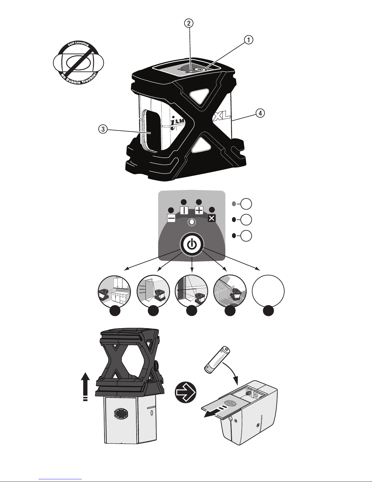
Operating Controls: (Fig. 1)
1. POWER button-4 Functions
2. Laser mode indicator (LED)
3. Laser output window
4. Battery compartment (under rubberized sleeve)
• Heavy Duty magnetically dampened compensator eliminates error by quickly
self-leveling the laser.
• Out-of-leveling range sensor triggers the beams to automatically blinks when the unit
is moved out of its ±4° self-leveling range.
4 Function Button: (Fig. 2)
1 Horizontal Laser Line 2 Vertical Laser Line 3 Laser Cross
4 Tilt “Manual Mode” (Horizontal Line Only) 5 OFF
A - LED light illuminates green when unit is ON
B - LED light illuminates red in Manual Mode
C - LED light illuminates red and lasers blink when out of leveling range
58-ILM • 3
EN

OPERATION
1. Set the unit on a flat, smooth surface. The self-levelling range of the instrument is within
approx. ±4° in any direction.
2. Turn the unit on by pressing the POWER button. The indicator light should illuminate “green”
if the unit is within its leveling range.
If the indicator light illuminates “red” and the laser cross is flashing, the unit is out of its
self-leveling range. Position the unit to a more level surface.
2a. If the unit appears to be within its self-leveling range and the LED continues to blink, be sure
the unit contains good batteries.
3. If the unit fails to operate after completion of steps 1-2 above, contact customer service.
4. Turn the unit OFF by pressing the POWER button as many times as it takes to cycle through
the various functions before coming to the OFF position.
POWER
Remove the battery cover by sliding it towards the bottom of the instrument. If replacing batteries,
remove the existing batteries. Insert three “AA” cell batteries into the instrument. Check for
correct polarity.
Alkaline batteries offer the longest battery life when used in this instrument.
Note: Extreme temperatures and the use of batteries with different levels of charge can reduce
the operating time of the instrument. Always use batteries with the same power rating and from
the same manufacturer. For the proper disposal of the used batteries, see the section
“Environmental Protection”.
ACCURACY CHECK
As with any level reference instrument, we strongly recommend checking the instrument’s
calibration before initial use; then periodically to ensure proper reference.
Check the laser Instrument following these steps:
Checking the horizontal line front to back (Fig. 4)
1. Choose two walls approximately 16-ft (5m) apart.
2. Set up the instrument 1-ft from wall (W1), project the laser cross onto wall. (W1) and mark
the point “A1” where the laser cross hits the wall.
3. Rotate the instrument 180° and project laser cross onto the opposite wall. (W2) and mark the
point where the laser cross hits the wall “B1”.
4. Reposition the instrument 1-ft from wall (W2), project the laser cross onto wall. (W2) and
mark the point “B2” where the laser cross hits the wall.
5. Rotate the instrument 180° and project laser cross onto the opposite wall. (W1) and mark the
point where the laser cross hits the wall “A2”.
6. Measure the distance between “A1” and “A2” and between “B1” and “B2” . If the distances
are the same, the Instrument is in calibration. If the difference between the two sets of
points is greater than 1/2 the specified accuracy the instrument is out of calibration.
4 • 58-ILM
Checking the horizontal line side to side (Fig. 5)
1. Set the instrument up approximately 8ft (2.5m) from a wall that is as least 16ft (5m) long.
2. Project the laser cross 1ft(0.3m) from one corner. Mark point (A) along the horizontal laser
line 8ft (2.5m) from the intersection of the laser cross.
3. Rotate the instrument so that the laser cross is projected at the wall 15ft (4.6m) away from
the first laser cross point.
4. The deviation of the horizontal laser line from the point (A) marked previously should not be
greater than 1/2 the specified accuracy.
CALIBRATION
This unit is factory calibrated and should never need calibration. But if it needs to be calibrated, it
must be done by a factory authorized service center. Contact customer service at (815) 432-9200.
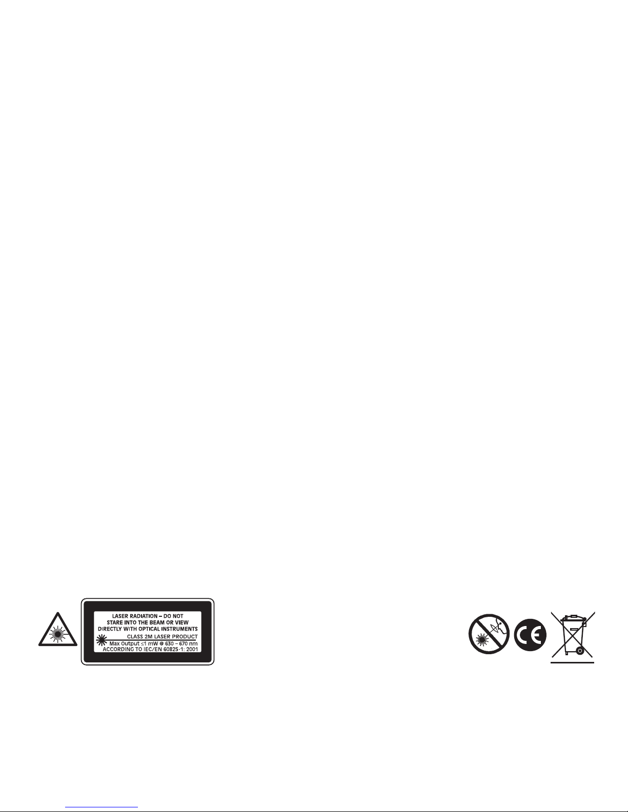
SAFETY AND CERTIFICATION
Working safely with this instrument is possible only when the operating and safety information are
read completely and the instructions contained therein are strictly followed.
Do not remove the label on the side of the housing.
The use in combination with other optical instruments, manipulations or use in other applications
other than described here, can lead to dangerous laser outputs.
Do not stare into the laser beam.
Do not direct the laser beam at other persons. Since the laser beam is of the focused type, check
the beam path over a relatively long distance and take the necessary precautions.
This laser complies with all applicable portions of title 21 of the Code of Federal Regulations set by
the Dept. of Health, Education, and
Welfare, the Food and Drug Administration, the Center for Devices, and the Bureau of Radiological Health.
The ILM has also been tested and complies with the CE certification requirements set forth in the
EC regulations 89/336/EEC and EN 61000-6-1 (EN50082-1), EN 61000-6-3 (EN50081-1)
and IEC 60-825-1.
58-ILM • 5
Complies with 21 CFR 1040.10 and 1040.11
except for deviations pursuant to Laser
Notice No. 50 dated July 26, 2001.

SPECIFICATIONS
LEVELING ACCURACY: ILM - ±1/4-in @ 30 feet (6mm at 9m)
ILMXL - ±5/32-in @ 30 feet (3mm at 9m)
LINE LENGTH 60-ft @ 30 feet (18m at 9m)
WORKING RANGE: ILM-Up to 32-ft (10m)
ILMXL-up to 100-ft (30 m),
dependent on illumination of area
FAN ANGLE: >120°
LASER DIODES: ILM - 635nm 5mw
ILMXL - 635nm 10mw
LASER CLASS: 2M
POWER: 3 “AA” batteries 1,5 V
COMPENSATOR TYPE: Coaxial(Gravity driven and magnetically dampened)
SELF-LEVELING RANGE: ±4º
SELF-LEVELING SPEED: ≤3 seconds
OUT-OF-LEVEL SENSOR: Yes
FEATURE: “Manual Mode Feature” allows tilting for
extreme angles
WEIGHT (WITH MOUNT): 1.8 lbs. (0.9kg)
WALL/TRIPOD MOUNT: 1/4- 20 thread
WARRANTY: 1 year
APPLICATIONS (Fig. 6)
• Floor and wall tiles • Installing closets
• Wallpaper, stencil work • Interior decoration
• Finish carpentry • Masonry work
• Wall fixtures: outlets, switches, lighting • Wall studs, partitions
• Door and window frames • Cabinets and shelving
• Drop ceilings • Wainscoting and paneling
• Remodeling project • Wall hangings: artwork, photos,
collectibles
• Machinery • Pipe and conduit
6 • 58-ILM

ACCESSORIES
Mini Laser Tripod (Fig. 7)
Tilts in two directions allowing the laser to set at any angle.
1. 1/4- 20 thread adapts to 5/8” x 11
2. Platform swivels in both directions to allow laser line positioning at any angle
3. Positioning Knobs
4. Folding tripod legs with non-skid rubber feet
5. 5/8-11 thread mounts to surveying tripod
6. Industrial strength Magnetic Mount
Universal Mount (Fig.8 )
1. Magnets for attachment to steel objects
2. Slots to attach mounting strap vertically or horizontally
3. 1/4- 20 or 5/8-11 threads for tripod
4. 1/4- 20 mounting stud for ILM
Once the Universal Mount is attached to the bottom of the ILM, the unit can be mounted on a 1/420 thread camera tripod, a 5/8” x 11 surveyor’s tripod or attached to any ferrous metal surface
(such as steel studs) by using the magnets located on the rear and bottom side of the mount, or
fixed thanks to the strap (supplied) to wood studs, etc.
MAINTENANCE AND CARE
The ILM is not waterproof. Do not allow the unit to get wet. Damage to internal circuits will result.
Do not leave the ILM out in direct sunlight or expose it to high temperatures. The housing and
some internal parts are made of plastic and may become deformed at high temperatures.
Do not store the ILM in a cold environment. Moisture will form on interior parts when warming up.
The moisture could fog up laser windows and cause corrosion of internal circuit boards.
When working in dusty locations, some dirt will collect on the laser window. Remove any moisture
or dirt with a soft, dry cloth. Do not use aggressive cleaning agents or solvents.
Store the ILM in its case when not in use. Remove batteries before storage of the instrument.
58-ILM • 7

ENVIRONMENT PROTECTION
Recycle raw materials instead of disposing as waste.
The machine, accessories and packaging should be sorted for environmental-friendly recycling.
Do not throw used batteries into house waste, fire or water but dispose of in an environmentally
friendly manner according to the applicable legal regulations.
WARRANTY
One Year Warranty. CST/berger,
a division of Stanley Works
, warrants this electronic measuring
tool against deficiencies in material and workmanship for a period of one year from the date of
purchase. Deficient products will be repaired or replaced at CST/berger's option. Proof of
purchase is required.
For warranty and repair information, contact:
Your Local Distributor, or CST/berger.
For U.S.A., Before returning the instrument to CST/berger, call (815) 432-9200 for
a Return Authorization Number from our Customer Service Department.
This Warranty does not cover deficiencies caused by accidental damage, wear and tear, use other
than in accordance with the manufacturer's instructions or repair or alteration of this product not
authorized by CST/berger.
Repair or replacement under this Warranty does not affect the expiry date of the Warranty. To the
extent permitted by law, CST/berger shall not be liable under this Warranty for indirect or
consequential loss resulting from deficiencies in this product.
Agents of CST/berger cannot change this warranty. This Warranty may not be varied without the
authorization of CST/berger.
This warranty may provide you with additional rights that vary by state, province or nation.
IMPORTANT NOTE: The customer is responsible for the correct use and care of the instrument.
Moreover he is completely responsible for checking the job along its prosecution, and therefore for
the calibration of the instrument. Calibration and care are not covered by warranty.
Subject to change without notice
8 • 58-ILM

MINI LASER ILM - AUTONIVELANTE
Gracias por haber escogido nuestro Mini Laser ILM.
Se recomienda leer atentamente las instrucciones de uso, realizar periódicamente
mediciones de control, como se indica en el manual, y realizar un mantenimiento
periódico del equipo para garantizar el máximo rendimiento y asegurar que la
precisión esté dentro de los margenes indicados por el fabricante.
MODELOS
58-ILM Mini Laser Autonivelante LaserMark ®.
Incluye: Laser, Bolsa.
58-ILMXL Mini Laser Autonivelante LaserMark ® con diodo
potenciado. Incluye: Láser, Mini-tripode, Bolsa
58-ILMXL-UM Mini Laser Autonivelante LaserMark ® con diodo
potenciado. Incluye: Láser, Bolsa y Monte Universal
Copyright© 2005 CST/berger,
a Division of Stanely Works
. Derechos reservados. Toda esta
información es propiedad de CST/berger .
Este documento no debe ser copiado o reproducido sin el consentimiento escrito de CST/berger.
LaserMark es una marca registrada de CST/Berger.
FUNCIONES (Figura 1)
1. Interruptor ON(conexión)/OFF(desconexión) - 4 funciones
2. LED Indicador de la función seleccionada
3. Ventana de salida del rayo
4. Tapa de las pilas (bajo la protección de goma)
• El compensador magnético muy robusto elimina cualquier tipo de error de nivelación al
autonivelar rápidamente el nivel.
• Un sensor hace que los rayos laser parpadeen automáticamente cuando la unidad está fuera de
su campo de autonivelación de +/- 4º.
Interruptor multifuncional (Fig. 2)
1 Horizontal 2 Vertical 3 Cruz
4 Inclinación – “Modo Manual” (sólo línea horizontal) 5 Apagado
A - El LED se enciende de color verde cuando el láser está encendido
B - El LED se enciende rojo cuando el láser funciona en Modo Manual
C - El LED se enciende rojo y el rayo parpadea cuando el láser está fuera de su rango de
autonivelación
58-ILM • 9
E

PUESTA EN FUNCIONAMIENTO
1. Colocar el ILM sobre una superficie lisa y a nivel. El campo de autonivelación es de
aproximadamente +/- 4º, en todas las direcciones.
2. Encender el láser pulsando el interruptor ON/OFF 1. El LED se enciende de color verde para
indicar que el instrumento está en su rango de autonivelación.
Si el LED se enciende rojo y el rayo láser parpadea, el láser está fuera de su rango de
autonivelación. Volver a posicionar el láser más a nivel y controlar.
2a. Si el láser parece que esté nivelado, pero el rayo sigue parpadeando, comprobar que las
baterías estén cargadas.
3. Si el instrumento no funciona, contacte con su vendedor.
4. Para apagar el láser pulsar el botón de conexión/desconexión varias veces para pasar a
través de las diferentes funciones hasta OFF.
INSERCIÓN/ CAMBIO DE LAS PILAS
El ILM funciona durante aproximadamente 25 horas con un diodo encendido, durante aprox. 20
horas con dos diodos encendidos, de uso intermitente con 3 baterías de 1,5 voltios. Si el
instrumento emite una luz débil, sustituir las baterías.
Retirar la protección de goma (Fig. 3). Retirar la tapa del alojamiento de las pilas. Introducir las
pilas o bien sustituir las gastadas por pilas nuevas. Ponga atención al introducir las pilas según la
adecuada polarización.
No utilizar pilas recargables!
La autonomía del instrumento se reduce en caso de temperaturas extremas o bien utilizando pilas
con distintos estados de carga.
Cambiar regularmente todas las pilas. Utilizar pilas de un solo fabricante y que tengan la
misma capacidad.
Para el correcto aprovechamiento de las pilas gastadas, ver el apartado “Medidas ecológicas”.
CONTROL DE LA PRECISIÓN
Controlar regularmente el ILM del siguiente modo:
1. Montar el aparato en su soporte y colocarlo en el centro entre dos paredes distantes entre
sí con una separación de 5 metros.
2. Presionar el interruptor conexión/desconexión 1.
3. Trasladando el instrumento, proyectar la cruz sobre ambas paredes y marcar el punto de
cruz de los dos rayos láser (Fig. 4 – Puntos D1 y D2).
4. Posicionar entonces el instrumento a una distancia de 60 cm. de una de las dos paredes y,
volviendo a trasladar el instrumento, hacer coincidir con el punto D1. Así se asegura que la
cota no ha cambiado.
5. Luego trasladar el instrumento otra vez y proyectar la cruz sobre la pared opuesta y realzar
la diferencia de la altura entre los puntos marcados sobre las dos paredes (D2 y D3).
6. Si la diferencia entre D2 y D3 es menor a 3 mm., el instrumento trabaja entonces con la
precisión especificada.
10 • 58-ILM
Comprobación de la línea horizontal ( Fig. 5)
1. Montar el aparato en su soporte y colocarlo a una distancia de 5 metros de la pared.
2. Presionar el interruptor conexión/desconexión 1.
3. Marcar el punto de cruz de los dos rayos láser, y marcar otro punto (A) a lo largo del rayo
láser horizontal a una distancia de 2,5 metros respecto del punto de cruz.
4. Trasladar el instrumento de modo que el punto de cruz de los dos rayos láser se proyecte en
la pared a una distancia de 5 metros del primer punto de cruz.
5. La desviación del rayo láser horizontal respecto al punto A previamente marcado no puede
ser mayor que 3 mm. (diferencia entre el punto A anterior y la posición actual del rayo en
equivalencia con el punto A).
CALIBRACIÓN
El ILM está calibrado en fábrica y no necesita otras calibraciones. Si fuera necesaria una
calibración, póngase en contacto con su proveedor o con un Centro de Servicio
Autorizado CST/berger.
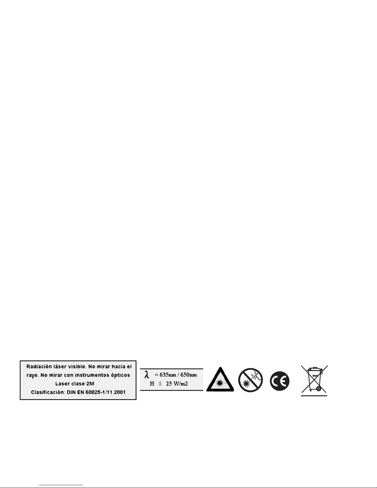
SEGURIDAD Y ESPECIFICACIONES
Es posible trabajar con el aparato sin peligro, solo después de haber leído atentamente las
instrucciones para el uso y las advertencias de seguridad, y siguiendo estrictamente las
instrucciones. No despegar la etiqueta del lateral del aparato.
El uso de instrumentos ópticos, controles, ajustes o procedimientos de funcionamiento distintos a
los especificados en el presente manual pueden provocar una exposición a radiación peligrosa.
No mirar hacia el rayo.
No apuntar el rayo láser hacia otras personas. A causa de la frecuencia del rayo láser, prestar
atención también al paso del rayo en caso de distancias largas y tomar las
precauciones necesarias.
El equipo cumple con todas las especificaciones del artículo 21 del Código de Regulación Federal
(U.S.A.) el Departamento de Sanidad, Educación, Alimentación y del Centro para la
Salud Radiológica.
El instrumento también cumple con las especificaciones CE según las normas 89/336/EEC, EN
61000-6-1 (EN50082-1), EN 61000-6-3 (EN50081-1) y IEC 60-825-1.
58-ILM • 11

DATOS TÉCNICOS
Precisión de Nivelado ILM - ± 6 mm a 9 m (1/4 pul a 30 pies)
ILMXL - ± 3 mm a 9 m (5/32 pul a 30 pies)
Longitud de las Líneas 18 m a 9 m de distancia
Distancia 10 m (ILM) o 30 m (ILMXL) dependiendo de las condi
ciones de luminosidad ambiental
Angulo de Desviación >120º
Tipo Láser ILM 635 nm 5mw - ILMXL 635nm 10mw
Clase Láser 2M
Alimentación 3 baterías de 1,5 V LR6
Compensador coaxial (por gravedad con amortiguamiento magnético)
Rango de Autonivelación +/- 4º
Velocidad de Autonivelación </= 3 segundos
Sensor de “fuera de nivel” si
Característica El « Modo Manual » permite de inclinar el instrumento
para hacer inclinaciones extremas
Peso 900 g incluido el soporte
Soporte Universal Rosca 1/4- 20
Garantía 1 año
APLICACIONES (Fig. 6)
• Aplicación de azulejos • Montajes de mobiliario
• Estanterías • Suelos y azulejos
• Paredes divisorias • Montaje de falsos techos
• Instalación de maquinarias • Tabiquería seca
• Puertas y ventanas • Interiorismo
ACCESORIOS
Mini trípode para láser (Fig. 7)
Se puede inclinar en dos direcciones, lo que posibilita que el láser se ajuste en cualquier ángulo.
1. Rosca adaptadora de 1/4-20 a 5/8-11
2. La plataforma gira en ambas direcciones para posibilitar el posicionamiento del láser en
cualquier ángulo
3. Palomillas giratorias para el posicionamiento
12 • 58-ILM
 Loading...