

Page 1
Motorcycle Alarm Systems
862
862
GB
INSURANCE APPROVED
MOTORCYCLE ALARM/IMMOBILISER USER GUIDE
862TH - 862TL
cod.: ISUT862T
FILENAME: ISUT862T.P65
Page 2

These Laserline systems are manufactured from the highest quality components
to ensure a long trouble free operating life and comply with the British insurance industry’s criteria for motorcycle security for Category MC1 product.
PRODUCT COMPLIANCE
Laserline 862TH/862TL - Combined Alarm/Immobiliser MC1 - MIRRC Test No. TMC1 177/1002
These instructions are intended to familiarise you with their simple operation.
Note: There are 2 versions of the 862T, the only difference between the units
are the internal inclination sensors. Depending on the mounting position of the
unit on the motorcycle, depends on the unit chosen by the installer.”H” is for
Horizontal mounting position and “L” is for Lateral mounting position.
NO DANGER FOR USER DUE TO THE
RADIO FREQUENCY EXPOSURE!
2
Page 3
OPERATING INSTRUCTIONS
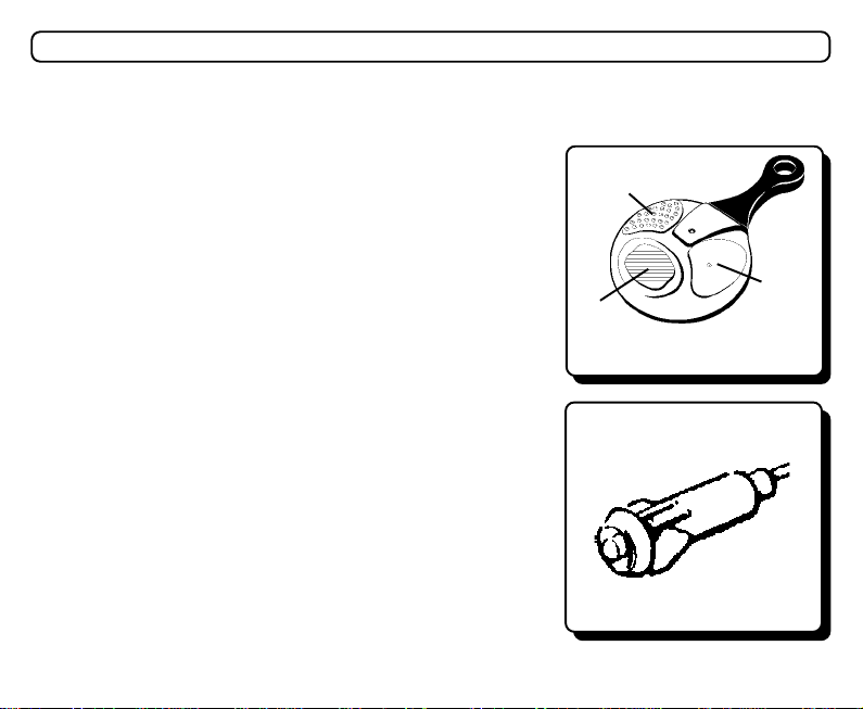
You would have received from your installer two remote control handsets (see fig. 1) and have
been shown the location of the Status LED (fig. 2).
ARMING THE ALARM SYSTEM
Press button A of the remote control; arming is signalled by two
flashes of the indicator lights and two acoustic tones (excludable).
When the alarm has been armed the LED will illuminate
(pre-alarm time) and after 30 seconds will flash regularly (0.5
second ON and 2 seconds OFF). An alarm condition will not be
generated by the tamper or inclination sensors until the system
has been set for 30 seconds (pre-alarm time).
Note: using button B within the pre-alarm time (30
seconds) it is possible to exclude the inclination sensor and/
or the siren for a setting period.
- Exclusion of the inclination sensor: press button B once, the
system confirms the programming with a single flash of the
indicator lights and a single acoustic tone (excludable).
- Exclusion of the siren: press button B twice within 2 seconds,
the system confirms the programming with two flashes of the indicator lights and two acoustic tones (excludable).
The functions will be reset the next time the alarm is
armed using the remote control.
DISARMING THE ALARM SYSTEM
Press button A of the remote control; disarming is signalled by
one flash of the indicator lights and one acoustic tone (excludable). If, during the armed period, the alarm did not sound, the
LED installed will extinguish (see “Alarm Trigger Signalling” - page 7).
C
B
A
fig. 1
fig. 2
3
Page 4

PANIC FUNCTION
Pressing button B for more than 1second will activate the siren and the indicator light
flashes for 15 seconds. To stop the panic feature prior to the 15 seconds, press any one of
the 3 buttons again on the remote control. This function is not available if the ignition is
switched on.
HAZARD FUNCTION
Pressing button C with the alarm disarmed and with the ignition key OFF, activates the
indicator lights to flash. To stop the indicator lights flashing press button C or put the
ignition key ON, otherwise the function is automatically limited to 4 minutes.
PASSIVE ENGINE IMMOBILISATION
Engine will automatically immobilise 30 seconds after switching OFF the ignition key or
30 seconds after the alarm has been disarmed by the remote control, if the ignition has
not been switched ON. Passive immobilisation is signalled by three acoustic tones (Not
excludable).
When this function is active, switching ON the ignition key will cause the system to generate
brief and repeated acoustic tones, whilst flashing the LED. When this function is active, it is
not possible to start the engine. To cancel the passive engine immobilisation, turn the ignition
key ON and press any button on the remote control Once within 10 seconds or enter your secret
remote code. If the passive engine immobilisation is not cancelled within 10 seconds of
switching ON the ignition key, the alarm will automatically arm itself and instantly sound an
alarm condition. If this occurs, press button A or enter your secret remote code to cancel the
alarm condition (with or without ignition key ON).
4
Page 5

SENSOR SELF-TESTING
SELF TEST FUNCTIONS
During the pre-alarm time (30 seconds), the LED will remain constantly ON, allowing you to perform
silent testing and verify the correct function of the tamper and inclination sensors. At the end of the prealarm time (30 seconds), the LED will flash regularly (0.5 second ON and 2 seconds OFF).
HOW TO SELF TEST THE FOLLOWING DETECTION FEATURES ON THE ALARM
The following features depend on the type of motorcycle and insurance criteria’s. Please consult your
alarm installer regarding the tamper detection applying to your motorcycle.
STANDARD INSTALLATION DETECTION
INCLINATION SENSOR
Arm the alarm by remote control; The LED will be constantly ON. Changing the orientation of motorcycle will cause the LED to blink off for 1 second indicating that detection occurred.
IGNITION SENSOR
Arm the alarm by remote control; any attempt to start the motorcycle by switching on the ignition will
cause an immediate alarm condition.
SELF-POWER SENSOR
Arm the alarm by remote control; Removal of the alarm system fuse or disconnection of motorcycle
battery will cause an immediate alarm condition.
Note: For servicing of motorcycle battery, disarm the alarm before disconnecting battery. Reconnecting the power to the alarm within 6 minutes, will cause the alarm to automatically enter into Garage
Function. Reconnecting the power to the alarm after 6 minutes, will cause the alarm to remain in the
disarm state.
5
Page 6

OPTIONAL TAMPER DETECTION
SEAT SENSOR/SIDE PANEL, ETC.
Arm the alarm by remote control; The LED will be constantly on, releasing the seat/side panel, etc. will
cause the LED to blink off for 1 second indicating that detection occurred. Note: A connecting
cable from the alarm may be attached to the base of the seat/side panel. This cable
has a connector to allow removal of seat/side panel and should always be reconnected when the seat/side panel is refitted. Failure to reconnect will mean the alarm
will not sense the seat/side panel being released. Ensure the seat catch/side panel
mount is kept clean and free from dirt and grease. When refitting seat/side panel,
ensure cable is not trapped or damaged. If the cable is not reconnected to the seat/
side panel the alarm will still operate normally except no detection of the seat/side
panel being released will occur.
SIDE STAND SWITCH
Arm the alarm by remote control; The LED will be constantly ON, releasing the side stand
will cause the LED to blink OFF for 1 second indicating that detection occurred.
GARAGE MAGNETIC/INFRA-RED SENSOR/S
Arm the alarm by remote control; The LED will be constantly ON, moving the magnet from
the contact switch/create body movement within the range of the infra-red sensor will cause the LED to blink OFF for 1 second indicating that detection occurred.
NOTE: Every time the magnetic contact or the infra-red sensor sends an alarm signal, the
red LED on the sensor lights for 2 seconds. The sensors have a battery saving function.
After an alarm signal as been transmitted to the alarm by a sensor, the sensor is inhibited
for 30 seconds and it must not detect any variations (keep still or move away from the protected area), otherwise this time will be extended and the sensor will not emit any alarm
signal until a least 30 seconds have past without detecting.
6
Page 7
ALARM TRIGGER SIGNALLING
FLASH CODES
If an alarm condition was generated whilst the system was armed, when the system is
disarmed the direction indicator lights will flash briefly (½ second) and an audible tone
(excludable) will be produced to indicate that an alarm condition has occurred. For 30
seconds after the system is disarmed and the ignition key is OFF, you can check the alarm
memory by looking at the LED installed on the motorcycle, you can determine which
sensor generated the last alarm condition. The LED will begin flashing and the repeated
sequence of flashes will identify the relative sensor:
Note: Turning the ignition key ON or rearming the alarm system will reset the flash code
memory and the LED, will extinguish.
FLASH CODES ALARM CONDITION GENERATED BY
LED Off: No alarm condition occurred.
1 Flash/Pause: Alarm condition generated by INCLINATION sensor.
2 Flashes/Pause: Alarm condition generated by SEAT/SIDE PANEL/SIDE STAND sensor.
3 Flashes/Pause: Alarm condition generated by IGNITION SWITCH sensor.
4 Flashes/Pause: Alarm condition generated by POWER SUPPLY sensor.
5 Flashes/Pause: Alarm condition generated by INFRA-RED/CONTACT GARAGE sensor.
· When the ignition key is ON, it is not possible to arm the alarm.
VERY IMPORTANT
· In an alarm condition, the siren sounds for 30 seconds. At the end of this period the system
will stop sounding completely or pause for 5 seconds if a sensor is still detecting.
· All sensors have a limit of 10 consecutive alarm cycles (In line with existing and proposed
European Noise Abatement Regulations).
7
Page 8

PROGRAMMABLE FUNCTIONS
INCLINATION SENSOR SENSITIVITY PROGRAMMING
The inclination sensor has two sensitivity settings, which are programmable by the remote control.
To change between Low and High settings (factory setting is high) proceed as follows:
1) Turn the ignition key ON.
2) Within 10 seconds press button C on first remote control and then press button C on
the second remote control.
The alarm will respond with:
3 brief (½ second)acoustic tones and 3 brief flashes of the indicator lights = sensitivity set on Low
Repeat the procedure (points 1 and 2) to reset to High sensitivity, the alarm will respond with:
3 long (1 second) acoustic tones and 3 long flashes of the indicator lights = sensitivity set on High
Note: If motorcycle is parked on a busy main road and false alarms occur, disarm alarm
and verify which sensor triggered an alarm condition by checking the flash code from the
LED. If it indicates the inclination sensor, re-program sensitivity setting to Low.
ARM/DISARM ACOUSTIC TONES PROGRAMMING
To exclude the acoustic arming/disarming tones (factory set to include), proceed as follows:
1) Turn the ignition key ON.
2) Within 10 seconds press button B on first remote control and then press button B on the
second remote control.
The alarm will respond with:
2 brief (½ second) acoustic tones and 2 brief flashes of the indicator lights = tones disabled
Repeat the procedure (points 1 and 2) to include the acoustic tone, the alarm will respond with:
2 long (1 second) acoustic tones and 2 long flashes of the indicator lights = tones enabled
SECRET REMOTE CODE PROGRAMMING
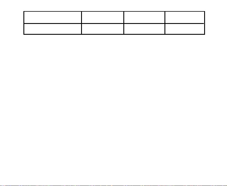
This function allows you to memorise your own secret disarm sequence , utilising a combination of the
3 buttons on the remote control. Before you program your secret remote code sequence ensure that you
have your “Emergency Pin Code” (see HOW TO KNOW YOUR EMERGENCY PIN CODE) noted in
the rear of these instructions. Study the examples to help you decide on the type of coded sequence you
would like to use. Button B can not be used for your first button in your coded sequence , this is to avoid
conflicts with the panic activation and inclination sensor/siren exclusion. Use the table or the table in
the rear of these instruction to note your coded sequence.
8
Page 9
Button ” “
Button ” “Button ” “
Number of presses
Combinations of less than 3 buttons are also accepted. To program the “secret remote code” , proceed
as follows:
1) Disarm the alarm system.
2) Turn the ignition key ON.
3) Press and hold button C of a functioning remote control.
4) Turn the ignition key OFF whilst maintaining the activation of button C on the remote control. The
LED mounted on the motorcycle will illuminate.
5) Release button C of the remote control.
6) Enter the desired sequence of buttons for the secret code. The sequence can be composed by a
combination of three buttons of the remote control; each button can be pressed a maxium of 15 times.
The LED will switch OFF each time a button is pressed.
7) After entering your coded sequence, turn the ignition key ON to exit the procedure.
Example 1: C button pushed 5 times + A button pushed 1 time + B button pushed 3 times.
Example 2: C button pushed 3 times + B button pushed 2 time + C button pushed 1 time.
Example 3: C button pushed 5 times .
NOTE:
- The “secret code” sequence can be removed by executing the above procedure untill point 5;
afterwards turn the ignition key ON to exit.
- To disarm the alarm during an alarm condition, firstly press any one of the 3 buttons on the remote
control (this will stop the siren sounding but not disarm the alarm), then enter your coded sequence.
- If you forget your secret code, disarm the alarm with your emergency pin code, after you disarm
the alarm, the alarm will automatically enter remote programming. Reprogramming all remote
controls will reset the system to a single press of button A for disarming.
9
Page 10

BATTERY SAVING FEATURES
Automatic Sleep Mode
The alarm system incorporates an automatic sleep mode which conserves the charge of the motorcycle’s
battery whilst the motorcycle is not in use. This feature is activated automatically if the motorcycle is
not used for 3 consecutive days (72 hours). In this mode, the alarm will not respond to the remote controls
and the LED will not flash. All sensors are still armed.
Garage Function
This function allows you to manually activate the sleep mode with only the immobilisation activated.
To activate this function proceed as follows:
1) Disarm the alarm system.
2) Turn the ignition key ON.
3) Press and hold button B of a functioning remote control.
4) Turn the ignition key OFF whilst maintaining the activation of button B on the remote control.One
long acoustic tone and one long flash of the indicator lights will signal the activation of the Garage
Function.
5) Release button B of the remote control.
To “wake up” the alarm, simply turn ON the ignition key and press any button on a remote control or
enter the secret code within 10 seconds.
When either of these functions are active, switching ON the ignition key will cause the system to generate
brief and repeated acoustic tones, whilst flashing the LED. If a button is not pressed or the secret code
is not entered within 10 seconds the alarm will automatically arm and instantly sound an alarm condition.
If this occurs, press button A or enter the secret code to cancel the alarm condition (with or without ignition
key ON). When either of these functions are active, the current draw is less than 0.5 mA.
Note:
- Passive immobilisation is not affected by Automatic Sleep Mode or Garage Function and will still
be active under these conditions.
- If optional radio transmitting “infra-red garage sensor” or “garage door contact switch” are
10
Page 11

programmed into the alarm system Automatic Sleep Mode will not activate.
Attention: to maintain the motorcycle’s own battery in a fully charged condition, it is recommended to run the engine periodically (once every 4 weeks) or if the motorcycle is being stored for
longer periods, then the battery should be maintained with a dedicated mains charger. Failure to
maintain the battery may result in the battery being completely depleted and requiring replace-
ment.
REMOTE CONTROLS AND EMERGENCY PIN CODE FEATURES
SELF-LEARNING OF REMOTE CONTROL CODES
The alarm comes with 2 remote controls that are already coded. To code another remote control or
to cancel one that is lost/stolen, it is necessary to have one original functioning remote control.
Then proceed as follows:
1) Disarm the alarm system.
2) Turn the ignition key ON.
3) Press and hold button A of a functioning remote control.
4) Turn the ignition key OFF whilst maintaining the activation of button A on the remote control and
then release button A.
5) The LED mounted on the motorcycle will flash 10 times, then turns on and remains on, indicating
the self-learning condition.
6) Press button A of the original remote control followed by the next remote controls you wish to
code. Acceptance of the code of each remote control is indicated by the LED extinguishing for
1 second and then re-illuminating.
7) After learning the last remote control wait 10 seconds. The alarm will indicate an emergency
pin code by generating acoustic tones, in synchronisation with the flashing of the LED (see next
section on emergency pin code). It is important to make a note of this pin code as it may
change from the original code displayed in the rear of these instructions. After the emergency
pin code has been displayed the alarm will automatically arm if the ignition is not switched
ON.Verify the function of all the remote controls at the end of this procedure. Any remote
control, lost or stolen will be cancelled from the memory of the alarm.
11
Page 12

• No more than 10 seconds must elapse between coding each remote control.
• The programme automatically exits from the self-learning procedure when 6 remotes have been
memorised or 10 seconds after the last remote control was coded.
• If a new remote control has been memorised, it is necessary to code in the original remote controls
if their continued use is desired.
• If all remote controls are lost, see HOW TO DISARM THE ALARM USING THE EMERGENCY
PIN CODE.
• Self-Learning of remote controls will cancel the “secret code” option and revert to single press of
button “A” for disarming.
The code sent by remote is variable i.e. it changes with every transmission. There are a billion
combinations. Arming/disarming occurs when a variable code is sent by the remote from a distance
of up to 5 metres from the motorcycle. This distance can change because of the external conditions
(remote or motorcycle battery condition, atmospherics, radio transmissions etc).
REMOTE CONTROL FAILURE
In the event of remote control failure, the alarm may be disarmed using the “EMERGENCY PIN
CODE”.
HOW TO KNOW YOUR EMERGENCY PIN CODE
At the end of self-learning procedure, the LED will indicate the emergency pin code with a flashing/
beeping (acoustic tone) sequence. To translate the pin code use the following example:
For the numbers n° of corresponding flashes
5
6
0
5
4
12
n° 5 consecutive LED flashe s
!
n° 6 consecutive LED flashe s
!
n° 10 consecutive LED flashes
!
n° 5 consecutive LED flashe s
!
n° 4 consecutive LED flashe s
!
VERY IMPORTANT
Rolling Code
2 sec. P ause
!
2 sec. P ause
!
2 sec. P ause
!
2 sec. P ause
!
2 sec. P ause
!
Page 13

On the example, the Pin Code to note at the end of these instructions would be 5 6 0 5 4.
It is imperative to note on a piece of paper this Emergency Pin Code, if it is different from
the original pin code displayed in the rear of these instructions. This pin code must then be
stored in a secure location. Note: if you intend to leave these instructions on the motorcycle,
the pin code in the back of these instructions should be removed for safe keeping.
This emergency code is derived from the last remote control/garage sensor memorised when you self-
learn a new remote control. If you want to change the pin code from the original code, you may have
to follow the self-learning procedure more than once alternating the first remote control until a new pin
code is given.
HOW TO DISARM THE ALARM USING THE EMERGENCY PIN CODE
If the remote control does not work correctly, then the following emergency procedure may be used
to disarm the security system temporarily:
1) With the alarm armed or passively immobilised, cause an alarm condition by turning the ignition
key to the ON position until the alarm starts to sound.
2) When the alarm starts to sound turn ignition key OFF.
3) The alarm will sound for 30 seconds and will then stop sounding. Then the LED located on the
motorcycle will come ON (illuminate). Within 4 seconds, switch ON/OFF the ignition key for 1
second.
4) After 2 seconds, the LED/Alarm will start to flash/beep. The alarm is now ready to accept the
Emergency Pin Code, displayed at the end of these instructions.
5) For each digit of the pin code, the LED/Alarm will flash/beep 10 times. You must switch ON the
ignition key for 1 second at the same time of the corresponding flash/beep. Turn OFF the ignition
key and start to count the next digit value and repeat until all 5 pin code digits have been inputted.
6) If the emergency pin code is correct, the alarm will disarm signalled by one flash of the indicator lights
and one acoustic tone. If not, the alarm will remain armed and steps 1-5 will have to be repeated
again.Once the alarm is disarmed, turn the ignition key ON within 30 seconds to enable starting of
the engine. If the ignition is not switched ON the alarm system automatically enters the “SELF-
LEARNING OF REMOTE CONTROL CODES” function at step 5. This allows you to program new
remote controls if all remotes are lost and to clear the “secret code” if you have forgotten your sequence.
13
Page 14
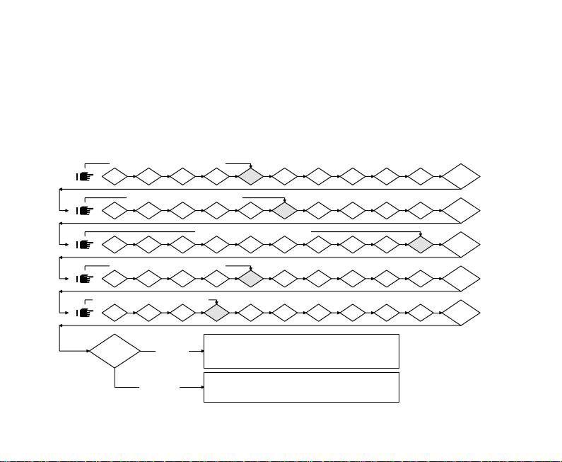
EXAMPLE: the code to be inserted is 5 6 0 5 4. First digit 5 - Wait 5 flashes for the first digit. After
the fifth flash has been completed and the LED has turned OFF, immediately turn ON the ignition
key for 1 second. Turn the ignition OFF and after a pause, the LED will flash for the next digit of the
Pin Code; Second digit 6 - Wait 6 flashes for the second digit. After the sixth flash has been
completed and the LED has turned OFF, immediately turn ON the ignition key for 1 second. Turn
the ignition OFF and after a pause, the LED will flash for the next digit of the Pin Code; Third digits
0 - For the 0 digit, the flashes to be completed on the LED are 10. Continue until all the digits have
been displayed and inputted correctly.
CODE
TURN ON THE IGNITION FOR 1 SEC.
55
5
55
66
6
66
00
0
00
55
5
55
44
4
44
1 72 103 94 6 8
TURN ON THE IGNITION FOR 1 SEC.
1 72 103 94 5 8
1 72
TURN ON THE IGNITION FOR 1 SEC.
1 72 103 94 6 8
TURN ON THE IGNITION FOR 1 SEC.
1 72 103 95 6 8
CODE
TURN ON THE IGNITION FOR 1 SEC.
3 94 5 6 8
CORRECT
5
6
5
4
GARAGE FUNCTION ACTIVATED
ALARM DISARMS WITH
WITHOUT ANY TIME RESTRICTION AND
WITHOUT ANY OPTICAL AND ACOUSTIC SIGNAL
AUDIBLE TONES AND VISUAL SIGNALS
2" PAUSE
2" PAUSE
2" PAUSE
10
2" PAUSE
2" PAUSE
INCORRECT
ALARM ARMED, SIREN ON FOR 30 SEC. AND THEN IT IS
POSSIBLE TO REPEAT THE EMERGENCY PROCEDURE
Note: If you use the Pin Code to disarm the alarm system, 30 seconds after turning OFF the ignition,
the alarm will automatically arm to ensure that the security of the motorcycle is not compromised.
14
Page 15
FLAT REMOTE CONTROL BATTERY SIGNAL
This function tells you that the remote control battery is almost depleted. You will notice that by
pressing any button on the remote control, the red LED on that remote control will flash
intermittently.It is recommended to use, Lithium 3V battery type CR2032. (See the ‘BATTERY
REPLACEMENT’ paragraph)
BATTERY REPLACEMENT
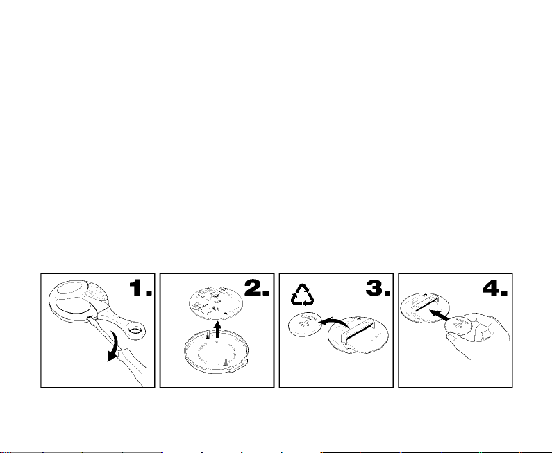
1 Open the remote by inserting a screwdriver between the two cases of the remote control (see
fig. 1). Lever to separate the two plastic cases.
2 Remove the printed circuit board (see fig. 2).
3 Remove used battery (fig. 3).
4 Insert the new battery taking care to only touch the sides of the battery (avoid touching the flat
surfaces of the battery and the printed circuit), into the centre compartment with the metal con-
tacts (see fig. 4).
5 Insert printed circuit board back into bottom case. Ensuring printed circuit board locates prop-
erly into locators in the bottom case.
6 Refit top of case and clip together.
15
Page 16

*OPTIONAL MAGNETIC/INFRA-RED GARAGE SENSORS
The optional Magnetic contact switch (800) and the Infra-red sensor (801) can be installed in your
garage/shed, to give added protection to your motorcycle whilst being stored. The sensors have
their own built-in radio transmitters that can transmit a signal to your alarm of up to a distance of 5
metres from the motorcycle. This distance can change because of external conditions (sensor
battery condition, atmospherics, radio transmissions etc). When a sensor detects, a radio signal is
sent to the alarm to sound an alarm condition. If you have purchased additional sensor/s for your
garage/shed from your installer and they have not already programmed the sensor/s for you, the
following procedure must be performed.
SELF-LEARNING PROCEDURE
The 800/801sensors have to be self-learnt into the alarm system like the remote controls.
To carry out the self-learning procedure, ensure batteries in the sensors are disconnected and all
functioning remote controls are available. Then proceed as follows:
1) Disarm the alarm system.
2) Turn the ignition key ON.
3) Press and hold button A of a functioning remote control.
4) Turn the ignition key OFF whilst maintaining the activation of button A on the remote control and
then release button A . The LED mounted on the motorcycle will flash 10 times, then turns on and
remains on, indicating the self-learning condition.
5) Press button A of the original remote control followed by the next remote controls you wish to
code; connect the battery terminals (fig.1/fig.4) of each magnetic contact or the infra-red
sensor; the LED on the sensor will light for 2 seconds; while the LED of the alarm will turn OFF
briefly confirming the self-learning.
6) After learning the last magnetic contact/infra-red sensor wait 10 seconds. The alarm will indi-
cate an emergency pin code by generating acoustic tones, in synchronisation with the flashing
of the LED (see “EMERGENCY PIN CODE”). It is important to make a note of this pin code as
it may change from the original code displayed in the rear of these instructions. After the
emergency pin code has been displayed the alarm will automatically arm if the ignition is not
switched ON. Verify the function of all the remote controls/magnetic contact/infrared senors at
16
Page 17

the end of this procedure.
You can learn a maximum of 6 units between remote controls and 800/801sensors into the alarm.
SENSOR TEST
It is possible to test the garage sensors during the pre alarm time (30 seconds), like any other sensors.
Arm the alarm by remote control; the LED on the motorcycle will be constantly ON. Move the magnet
from the contact switch/create body movement within the range of the infra-red sensor; this will cause
the LED on the motorcycle to blink OFF for 1 second indicating that the protected areas have been
detected.
After the pre-alarm time (30 seconds), the activation of a sensor will cause the alarm to activate the
siren.
It is possible, by the “alarm trigger signalling” function, to verify that a garage sensor caused an alarm
condition.
NOTE: every time the magnetic contact or the infra-red sensor sends an alarm signal, the red LED on
the sensor lights for 2 seconds. The sensors have a battery saving function. After an alarm signal as been
transmitted to the alarm by a sensor, the sensor is inhibited for 30 seconds and it must not detect any
variations (keep still or move away from the protected area), otherwise this time will be extended and
the sensor will not emit any alarm signal until a least 30 seconds have past without detecting.
EXCLUSION OF THE INFRA-RED SENSOR (801V1D ONLY)
It is possible to exclude the infra-red sensor by the appropriate switch situated on the plastic body of the
sensor. Switching the sensor back on will cause the LED on the sensor to illuminate for 2 seconds.
TECHNICAL DATA
Power supply:...................................................................................................................battery 9V
Battery type: .............................................................................................. MN 1604 6LR61 9 Volts
Battery life:................................................................................................................... 6-12 month
Radio transmitter frequency: ......................................................................................... 433.9 MHz
*The optional Magnetic contact switch (800) and the Infra-red sensor (801) are under redevelopment at the time of going to print, please refer to the instruction that are supplied with these
units for the latest information.
17
Page 18
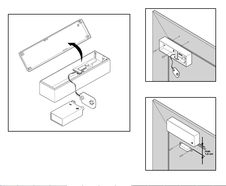
800 Magnetic Sensor
fig. 1
Tips for mounting the magnetic contact:
Avoid mounting the magnet on a ferrous surface (this will
attract the power of the magnet).
Mount magnet/contact on opening side of door and as high as
possible to avoid accidental damage.
18
fig. 2
Mount contact to door frame.
(see fig. 2)
fig. 3
Mount magnet to door . (see fig.3)
Page 19

862TH/862TL TECHNICAL DATA
POWER SUPPLY: ......................................................................................................... 12V DC
CURRENT DRAW WITH ALARM ON : .......................................................................... <3 mA
CURRENT DRAW WITH ALARM OFF : ......................................................................... <2 mA
CURRENT DRAW IN SLEEP MODE : ............................................................................ <0.5 mA
PRE-ALARM TIME: ....................................................................................................... 30 seconds
ALARM DURATION TIME: ........................................................................................... 30 seconds
1 STOP ENGINE RELAY CONTACTS CAPACITY: ....................................................... 7 Ampere
2 STOP ENGINE RELAY CONTACTS CAPACITY: ....................................................... 7 Ampere
19
Page 20

WARNING
ALARMS MUST NOT BE STEAM CLEANED OR PRESSURE WASHED.
BEFORE CARRYING OUT ANY ELECTRICAL WORK ON THE MOTORCYCLE,
ISOLATE THE SYSTEM BY REMOVING SYSTEM FUSE/MOTORCYCLE BATTERY
OR DAMAGE TO THE ALARM MAY RESULT!
NOTE
Alarms are only a deterrent against any theft, the use of a quality
secondary lock is still recommended.
20
Page 21

21
Page 22
LIFETIME WARRANTY
Product warranty covers units to be free from defects in manufacture for the lifetime ownership of
the original motorcycle, in accordance with the terms and conditions of this warranty document.
Any product, which is deemed to be defective, will be replaced or repaired. Accessories including
remote controls, touch keys and additional modules are guaranteed for a period of 12 months from
date of installation.
TERMS AND CONDITIONS
1. Product must be installed by an authorised qualified installer.
2. If product is transferred by an authorised installer onto another motorcycle then in this
case the warranty reverts back to 2 years from the date of the original installation.
3. Warranty is not transferable by the original customer to other owners of the product or
accessory.
4. The customer must complete and return the warranty registration document within 21
days from date of purchase in order for the warranty to be valid.
5. The warranty covers product only and not the quality of the installation. The warranty for
installation is provided by the installer. We cannot be held responsible for costs arising
due to incorrect installation.
6. All warranty claims must be directed through the original installer, accompanied by the
original invoice, detailing date of installation and annual service record. Failure to do this
will render the warranty invalid.
7. Continuance of product warranty is subject to an annual product service check for which a
small charge may be levied by any authorised installer. Evidence of service check record
must be provided in support of warranty claims.
8. Warranty does not cover costs incurred for breakdown assistance or motorcycle recovery,
due to product or accessory failure. Warranty does not extend to reimbursement for
damage due to defects in products or accessories.
22
Page 23

EXCLUSIONS FROM WARRANTY
Warranty will not be valid due to the following:
1. Poor response to transmitters due to abnormally high electromagnetic interference.
2. Low battery voltage in transmitters.
3. Abuse or mistreatment of any product or accessory.
4. Loss or damage due to accident, fire, lightening, explosion, flood or water, war or civil
disturbances.
5. Damage caused by external electrical source or from abnormal variation or failure of
power supply.
6. Failure caused by installation of accessories not approved by the product manufacturer.
7. Failure of product occurring outside Great Britain.
8. Replacement of defective parts within the guarantee period does not include consumable
parts or include labour.
9. If product is repaired by a non authorised installer the product will cease to be covered by
the warranty.
10. Original manufacturer negligence.
CONSUMER SUMMARY
All warranties are limited to the duration of this warranty.
This is the complete warranty and no other express or implied warranty is valid. Nothing in this
warranty shall affect your statutory rights.
Manufacturer declines any responsibility for damage of the alarm/immobiliser and the motorcycle
NOTE
electrical system due to WRONG INSTALLATION OR TAMPERING.
LASERLINE SpA RESERVES THE RIGHT TO EFFECT CHANGES OF THE PRODUCT WITHOUT
FURTHER NOTICE.
23
Page 24
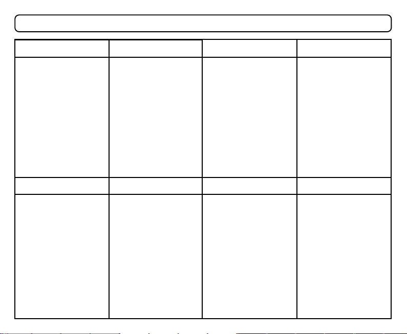
Service Inspection
1 YRS
Installer’s Stamp
Cert. No.
Reg. No.
Date.
Signature
Installer’s Stamp
Cert. No.
Reg. No.
Date.
Signature
24
2 YRS 3 YRS
Installer’s Stamp
Cert. No.
Reg. No.
Date.
Signature
Installer’s Stamp
Cert. No.
Reg. No.
Date.
Signature
Installer’s Stamp
Cert. No.
Reg. No.
Date.
Signature
Installer’s Stamp
Cert. No.
Reg. No.
Date.
Signature
4 YRS
Installer’s Stamp
Cert. No.
Reg. No.
Date.
Signature
PLEASE NOTE7 YRS6 YRS5 YRS
The above Service
Inspection must be
carried out in order
to ensure the
validity of the
Customer Lifetime
Warranty
Page 25
CUSTOMER LIFETIME WARRANTY REGISTRATION
Alarm/Immobiliser Model No. ………...…………….............Make………………………..............…….
Accessories Fitted ………………………….............................Model………………….....................……
Date of Installation……………………………….....................Reg.No. ……….…..........……….....…….
Customer Name………………………………........................Year of Manufacture………….................
Address………………………………........................………………………………...............……………..
.................................................................................................................................................................
Postcode ………………………......................…...........Tel No. .................. ……….............……………
Installer Name ………………….......…………….........Account No. …...................……………....……..
Address………………………………………………………………………………….........………………...
Postcode …………………………………………….........Tel No. ……................…..................…………
I have read and understood the terms and conditions of the Customer Lifetime Warranty.
Customer Signature.......................................................................
FAILURE TO COMPLETE AND RETURN THIS CARD WILL
IMPORTANT NOTE
RESULT IN YOUR WARRANTY BECOMING VOID.
25
Page 26

Return to:
Laserline Direct Limited
33, Craven Court
Winwick Quay
Warrington
Cheshire
WA2 8QU
26
Page 27
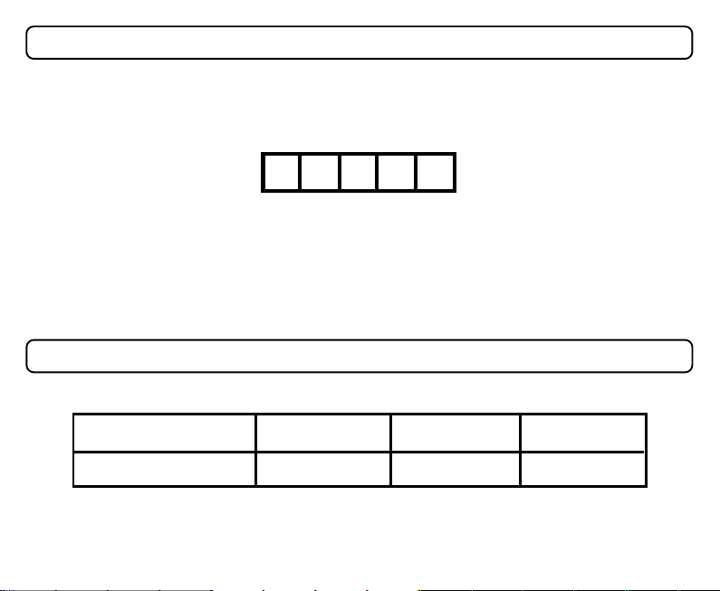
EMERGENCY PIN CODE
YOUR PIN CODE IS:
Note: If your pin code has not been completed by your installer please follow “SPECIAL
FUNCTIONS - Self-Learning Of Remote Control Codes” procedure to obtain your pin code.
SECRET REMOTE CODE
Number of presses
Button ” “
Button ” “Button ” “
Page 28

Dealer Stamp
Our commissioned Sales and Support Agents in the UK areOur commissioned Sales and Support Agents in the UK are
Our commissioned Sales and Support Agents in the UK are
Our commissioned Sales and Support Agents in the UK areOur commissioned Sales and Support Agents in the UK are
33, Craven Court - Winwick Quay - Warrington - Cheshire WA2 8QU
Laserline Direct Limited
 Loading...