

cod.: ISUT290I2-UK
FILENAME:ISUT290I2-UK.P65
GB
290i2/291 INSURANCE APPROVED
ALARM/IMMOBILISER USER GUIDE
®
CAR ALARM SYSTEMS

These systems are manufactured from the highest quality components to ensure a long
trouble free operating life and comply with the British insurance industry’s criteria for
vehicle security for Category 1 product - 291 and Category 2
290i2, as evaluated by Thatcham (MIRRC).
Note: Category 2 1 (L2 1) product – 290i2 alarm system is only to be fitted in conjunction
with a Category 2 (L2) immobiliser to obtain Category 1 status for the vehicle security.
These instructions are intended to familiarise you with their very simple operation.
KEY
* Optional.
** Vehicle dependent.
1 (L2
1) product –
NO DANGER FOR USER DUE TO THE
RADIOFREQUENCY EXPOSURE!
WARNING
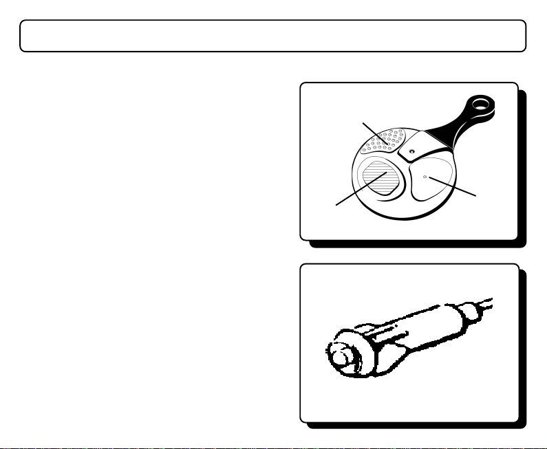
ALARMS MUST NOT BE STEAM CLEANED OR PRESSURE WASHED.
BEFORE CARRYING OUT ANY ELECTRICAL WORK ON THE VEHICLE ISOLATE
THE SYSTEM BY REMOVING SYSTEM FUSE/VEHICLE BATTERY OR DAMAGE
TO THE ALARM MAY RESULT!
OPERATING INSTRUCTIONS
You would have received from your installer, two remote controls (see fig. 1) and have been shown
the location of the Status LED (fig. 2).
FUNCTIONS
Button A: arming/disarming of the alarm (290i2)
Button A: arming/disarming of the alarm and
immobiliser (291);
Button B: panic, ultrasonic exclusion function;
Button C: special programmable functions; boot
opening* or lighting*.
ARMING THE ALARM SYSTEM
Press button A (arm/disarm), located on the right of
the remote control (see fig. 1). The direction indicator
lights will flash twice and the alarm may give two
audible tones (programmable function) will be generated
at the same time to indicate that the alarm system has
been armed. The power locks* will close along with the
electric power windows* and electric sunroof*. The red
LED (see fig. 2) in the passenger compartment will
remain on for 30 seconds (pre-alarm time) and then will
begin flashing in a regular pattern.
C
B
A
fig. 1
fig. 2

DISARMING THE ALARM SYSTEM
Press button A (arm/disarm), located on the right of the remote control (see fig. 1). The direction
indicator lights will flash once and the alarm may give one audible tone (programmable function)
generated at the same time to indicate that the alarm system has been disarmed. The power locks*
will open and, if button C is activated, all the courtesy lights will turn on for 10 seconds. If an
alarm was generated while the system was armed, when the system is disarmed the direction
indicator lights will flash briefly (½ second) and an audible tone will be produced to indicate that an
alarm condition has occurred. To identify the sensor that caused the alarm, consult the “ALARM
AUTO-DIAGNOSTICS” paragraph.
SENSOR ACTIVATION AFTER ARMING
Once armed an alarm condition will be generated by power supply interruption and the turning ON
of the ignition key. An alarm condition will not be generated by the door/bonnet/boot being opened
or interior (ultrasonic/microwave sensors) movement until the alarm has been armed for 30
seconds (pre-alarm time).
ALARM CONDITION
When a sensor is activated, the system will generate an alarm condition: direction indicators flash and
the siren sounds for 30 seconds (alarm cycle). At the end of the alarm cycle, if the same sensor is still
activated, the alarm will generate an alarm cycle again.
ALARM CYCLE LIMITATION
The system will automatically exclude the sensor, which has generated 8 alarm cycles. All the
other sensors will continue to protect the vehicle. The maximum number of alarm cycle for every
sensor is 8, except for power supply interruption sensor (10 alarm cycles).
Note: If a sensor continues to remains activated whilst in the pre-alarm time, the system will
automatically exclude this sensor at the end of the pre-alarm time and not generate an alarm
condition. When the alarm system is next disarmed the direction indicator lights will flash briefly (½
second) and an audible tone will be produced to indicate that a senor was activated whilst arming.
To identify the sensor that was activated, consult the “ALARM AUTO-DIAGNOSTICS” paragraph.

BUTTON ‘B’ FUNCTIONS (Panic and Excluding the ultrasonic sensors and electric power
window* module)
Panic function: Pressing this button twice within a maximum of 3 seconds activates the siren for 10
seconds and the additional siren*. To stop the sound prior to the 10 seconds, press button ‘B’ on the
remote control.
Excluding the ultrasonic sensors and electric power window* module using the remote
control: Arm the alarm system using button ’A’ on the remote control; within 30 seconds (pre-
alarm time) press button ‘B’ of the remote control. The direction indicator lights will flash once and
you will hear a brief audible tone to confirm the programming. Now the ultrasonic sensors and
accessory output are temporarily deactivated.
The functions will be reset the next time the alarm is armed using the remote control or
an electronic key.
IMMOBILISATION (291 only)
When the alarm system is armed, an internal immobiliser (921K) isolates the vehicle starting
circuits (e.g. starter motor/fuel pump) to prevent running of the vehicle.
PASSIVE IMMOBILISATION (291 only)
The internal immobiliser (921K) activates automatically after 30 seconds of turning the ignition
OFF or 60 seconds after the alarm has been disarmed using the remote control, without turning
the ignition key ON. The LED (see fig. 4) installed on the dashboard will begin flashing rapidly to
indicate that the internal relay is in the immobilised condition. Whilst in the passive immobilised
condition, when the ignition is turned ON the alarm will generate audible tones. If the passive
immobilisation is not disarmed by the 10
th
audible tone the alarm will fully arm and then sound an
alarm condition.
To disarm the passive immobilisation, turn the ignition key to the ON position and press button “A”
of the remote control. The audible tones will be interrupted and the LED will stop flashing.

DISARMING USING THE EMERGENCY PIN CODE (290i2 Only)
This function only applies if there is no optional electronic key.
If all the remote controls have been lost or are malfunctioning, you can disarm the alarm system
using the “emergency pin code”.
HOW TO KNOW YOUR EMERGENCY PIN CODE
To display the emergency pin code (Pin Code), wait 10 seconds after the memorisation of the last
remote control or just follow points 1,2,3 of the “Auto-learning” procedure and wait 10 seconds.
The system will use the LED on the dashboard to present a series of 5 flashes that will correspond
to 5 numbers.
For the numbers n° of corresponding flashes
5
6
0
5
4
On the above example, the Pin Code to note at the end of these instructions would be 5 6 0 5 4.
It is imperative to note on a piece of paper this pin code, if it is different from the original pin code
displayed in the rear of these instructions. This pin code must then be stored in a secure location.
Note: If you intend to leave these instructions in the vehicle, the pin code in the back of these
instructions should be removed for safe keeping.
This pin code is derived from the first remote control memorised when you auto-learn a new
remote control. If you want to change the pin code from the original code, you may have to follow
the auto-learning procedure more than once alternating the first remote control until a new pin
code is given.
n° 5 consecutive LED flashes
n° 6 consecutive LED flashes
n° 10 consecutive LED flashes
n° 5 consecutive LED flashes
n° 4 consecutive LED flashes
2 sec. Pause
2 sec. Pause
2 sec. Pause
2 sec. Pause
2 sec. Pause
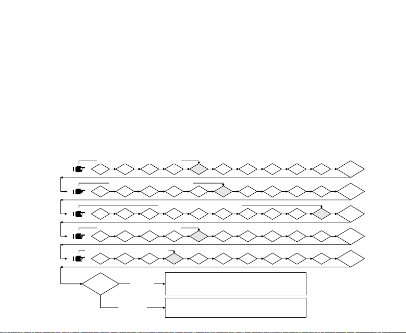
HOW TO DISARM THE ALARM USING THE EMERGENCY PIN CODE
If your transmitter does not work correctly or has been lost, to disarm the alarm system you must
insert the “emergency pin code” by doing the following:
1) With the alarm armed, activate the siren by opening the door on the driver’s side;
2) Enter the vehicle. The alarm will stop sounding after 30 seconds and then the LED installed on
the dashboard will illuminate for 5 seconds. Within the 5 seconds, turn on the ignition key for
1 second;
3) The LED installed on the dashboard will start to flash and the alarm is ready to accept the Pin
Code. If not interrupted, the LED will flash 10 times. Wait for the flashes corresponding to
each digit of your Pin Code to be displayed, then turn ON the ignition key for 1 second only
after the LED is off. Read Pin Code at the end of these instructions from left to right. For a
better understanding, see the example.
CODE
TURN ON THE IGNITION FOR 1 SEC.
2
55
5
55
66
6
66
00
0
00
55
5
55
44
4
44
1
TURN ON THE IGNITION FOR 1 SEC.
2
1
2
1
TURN ON THE IGNITION FOR 1 SEC.
2
1
TURN ON THE IGNITION FOR 1 SEC.
CODE
2
1
CORRECT
INCORRECT
4
3
4
3
TURN ON THE IGNITION FOR 1 SEC.
4
3
4
3
3
4
ALARM DISARMS WITHOUT ANY AUDIBLE
WITHOUT ANY TIME RESTRICTION AND
WITHOUT ANY OPTICAL AND ACOUSTIC SIGNAL
ALARM ARMED, SIREN ON FOR 30 SEC. AND THEN IT IS
POSSIBLE TO REPEAT THE EMERGENCY PROCEDURE
6
5
5
6
6
5
6
5
6
5
GARAGE FUNCTION ACTIVATED
TONES AND VISUAL SIGNALS
8
7
7
7
7
7
9
8
9
8
9
8
9
8
9
2" PAUSE
10
2" PAUSE
10
2" PAUSE
10
2" PAUSE
10
2" PAUSE
10
EXAMPLE: the code to be inserted is 5 6 0 5 4. First digit 5 - Wait 5 flashes for the first digit. After
the fifth flash has been completed and the LED has turned OFF, immediately turn ON the ignition
key for 1 second. Turn the ignition OFF and after a pause, the LED will flash for the next digit of the
Pin Code; Second digit 6 - Wait 6 flashes for the second digit. After the sixth flash has been completed and the LED has turned OFF, immediately turn ON the ignition key for 1 second. Turn the
ignition OFF and after a pause, the LED will flash for the next digit of the Pin Code; Third digits 0 For the 0 digit, the flashes to be completed on the LED are 10. Continue until all the digits have
been displayed and inputted correctly. If the code inserted is correct, the alarm will automatically
DISARM without any audible tones and visual signals. If the code is incorrect, an alarm condition
will occur.
ALARM ARMING/DISARMING USING THE ELECTRONIC KEY (Optional on 290i2)
fig. 3
ARMING THE ALARM SYSTEM
The alarm system can also be armed using the electronic key (See fig. 3). Placing the key on the
LED receptacle (See fig. 4) arms the alarm without activating the power locking system. The
direction indicator lights will flash twice and the alarm may give two audible tones, (programmable
function) generated at the same time to indicate that the system has been armed. Then the LED
(see fig. 4) in the passenger compartment will remain on for 30 seconds (pre-alarm time) and
fig. 4

then will begin flashing in a regular pattern. Activating the system with the electronic key disables
the SENSOR SELF-TESTING functions (see the SENSOR SELF-TESTING paragraph).
DISARMING THE ALARM SYSTEM
If the alarm system was previously armed using the electronic key, you will have 10 seconds to
enter the vehicle before an alarm condition occurs. Therefore you can open the power locking
system manually, enter the car and place the electronic key on the receptacle (see fig. 4). If an
alarm condition occurs, consult the paragraph “ALARM AUTO-DIAGNOSTICS” paragraph.
SENSOR SELF-TESTING
This facility confirms the correct operation of interior/doors/boot/bonnet detection circuits. This is
indicated by a series of audible tones/illumination of the direction indicators and a series of flashing of the dashboard LED, when one of the circuits is triggered within the pre-alarm time. To self
test the detection circuits:
DOORS/BOOT/BONNET DETECTION CIRCUITS
1 Arm the alarm with the remote control.
2 Unlock the vehicle.
3 Within the first 30 seconds of arming the alarm open and close all doors/boot/bonnet. The
alarm will respond with 3 audible tones, 3 flashes of the direction indicators and 3 flashes of
the LED. If vehicle is fitted with a courtesy light delay system, you may have to wait for the courtesy light to go out before testing the next doors/boot/bonnet detection circuits.
INTERIOR DETECTION CIRCUIT (Ultrasonic/microwave sensors)
1 Sit inside the vehicle.
2 Arm the alarm with the remote control.
3 Within the first 30 seconds of arming the alarm, create movement in front of the interior sen-
sors (normally mounted at top of windscreen). The alarm will respond with a constant audible
tone, the direction indicators will illuminate and the LED will go out.

ALARM AUTO-DIAGNOSTICS
If an alarm was generated while the system was armed, when the system is disarmed the direction
indicator lights will flash briefly (½ second) and an audible tone will be produced to indicate that an
alarm condition has occurred. At any time while the system is disarmed and the ignition key is off,
you can check the alarm memory by pressing buttons A and B on the remote control at the same
time. By looking at the LED installed on the dashboard, you can determine which circuits generated
the last 5 alarm conditions. The LED will begin flashing and the sequence of flashes will identify the
relative sensor:
DIAGNOSTICS FLASH CODES
LED OFF: no alarm conditions have occurred
2 FLASHES/PAUSE: the ULTRASONIC sensor generated an alarm condition
3 FLASHES/PAUSE: the DOOR/HATCH sensor generated an alarm condition
4 FLASHES/PAUSE: the BONNET sensor generated an alarm condition
5 FLASHES/PAUSE: the IGNITION KEY sensor generated an alarm condition
6 FLASHES/PAUSE: the POWER SUPPLY sensor generated an alarm condition
7 FLASHES/PAUSE: the BOOT/ADDITIONAL sensor generated an alarm condition*
8 FLASHES/PAUSE: the GARAGE sensor generated an alarm condition*
9 FLASHES/PAUSE: FLAT REMOTE CONTROL BATTERY
10 FLASHES/PAUSE: FLAT INTERNAL BATTERY AUTO-POWER SUPPLY
Attention:
The causes of the alarm will be displayed in sequence from the last to the fifth. At the end of
the display, to repeat the five codes press both buttons again on the remote control.
After checking the flash codes, the memory will be cleared when the alarm is next armed.

The memory of the last five alarm conditions will be cleared when the alarm power supply is
disconnected.
PROBLEM SOLVING
If your alarm sounds for no apparent reason, please refer to the DIAGNOSTICS FLASH CODES for
possible condition. Possible causes of the alarm condition could be:
- Vehicle has been tampered with.
- Windows/sunroof are not fully closed.
- Doors/boot/bonnet are not fully closed.
- Check that the air vents have not been left open. Air movement within the vehicle may trigger
your alarm.
- Check the doors/boot/bonnet contact switches operate correctly.
- Articles inside the vehicle are moving e.g. jacket, hanging toys or accessories.
SPECIAL FUNCTION
BUTTON “C” FUNCTION OPTIONS (boot opening/parking lights/courtesy lights)
These functions are addition to the standard installation and may require additional components.
BOOT OPENING*: Pressing button “C” once, will unlock or release the boot lock, allowing you quick
entry to the boot area without unlocking the vehicle doors (alarm armed or disarmed). If the alarm is
armed at the time of pressing button ”C” the alarm will disarm for 30 seconds.
THE PARKING LIGHTS/COURTESY LIGHT LIGHTING*: Pressing button “C” once will activate an
output for 10 seconds (alarm armed or disarmed). This function can be used to light the internal

courtesy lights or the external sidelights, illuminating the area near the car.
Pressing button “C” again prior to the 10 seconds causes the lighting to switch off (vehicle with
courtesy lights delay system may take longer to switch off).
COMFORT FUNCTION* (only for vehicle equipped with Comfort Closing of locking/
windows/roof**)
For cars equipped with Comfort Closing function, the windows can be closed just by pressing and
holding button ‘A’ of the remote control. When the windows have reached the required height,
release button ‘A’ and the windows will stop immediately. In the same way, if button ‘A’ is pressed
and held while disarming the alarm, the power locks will open and the windows will open
automatically**. When the button is released, the windows will stop immediately.
CASUAL RE-ARMING*
On your return to the vehicle, if you disarm the system but do not enter the vehicle (doors/bonnet/
boot) within 30 seconds, the alarm will automatically re-arm itself (reactivating the power locking
system but not the accessory output). Useful if you accidentally disarm the alarm from a distance
without knowing. This function is cancelled if you enter the vehicle (doors/bonnet/boot) within 30
seconds from when the alarm is disarmed.
PASSIVE ARMING *
This function allows the alarm to be armed automatically without using the remote control: Turn off
the ignition key and exit the vehicle. 10 seconds after the last door is closed/or 10 seconds after
the courtesy lights go out the alarm will arm (the function does not activate the power locking
system and the accessory output). Please ensure you lock the doors using the normal ignition key!
SAFETY LOCKING*
This function automatically closes the power locking system in the following situation: Disarm the
alarm with the remote control or electronic key. Enter vehicle and only after having closed all the
protected areas (doors/boot/bonnet), turn the ignition key ON. The power locking system will
automatically lock the doors after 5 seconds. The doors will unlock automatically when the ignition
key is turned OFF.

IMPORTANT NOTE: Only to be used if the car is equipped with an original “crash sensor”
(inertia switch) power locking system that is activated if an accident occurs. If not, a similar one
available on the market must be installed. Laserline S.p.A. will be not be held responsible if users
do not comply with this note.
SIREN EXCLUDING
Disarm the alarm system using the remote control. Enter the vehicle and make sure that all doors/
bonnet/boot are closed. Turn the ignition key ON; within 5 seconds press button “B” of the remote
control once. At the same time that you press button ”B”, you will hear a brief audible tone to
confirm the programming. Now the siren sound is temporarily excluded and if an alarm condition
occurs, only the direction indicator lights will flash. This function may be necessary in hospital
parking areas, ferries, skiing resorts etc.
The function will be reset the next time the alarm is armed using the remote control or an
electronic key.
ATTENTION: excluding the siren does not deactivate the additional siren/vehicle horn/paging
system and the panic function.
FLAT INTERNAL BATTERY POWER SUPPLY SIGNAL
If your alarm system is equipped with an internal battery, it can automatically check the battery
charge and charging circuit. In case of a malfunction, the system communicates the problem to
you through the “Alarm auto-diagnostics” function by flashing the LED 10 times.
ADDITIONAL SIREN*
This function allows the alarm to be connected to an additional siren/vehicle horn/paging system
and can be programmed to obtain a continuous or intermittent output for the entire alarm cycle.
TYPE OF SOUND*
Two different types of sound can be programmed: monotone or modulated (manufacture default to
monotone).
KEY * Optional. ** Vehicle dependent.

AUTO-LEARNING
Auto-learning function allows you to program new remote controls/electronic keys or cancel lost
remote controls/electronic keys.
To carry out the auto-learning procedure, at least one functioning remote control or electric key
must be available. Then do the following:
Open the door on the driver’s side;
Turn the ignition key ON;
Press and hold button “A” on the functioning remote control or insert and hold an electronic
key into the receptacle.
Now turn off the ignition key and release button “A” or remove the electronic key from the
receptacle. The red LED installed on the dashboard will turn on and remain on, indicating the
auto-learning condition.
At this point, press button “A” of all the remote controls or insert the electronic keys into the
receptacle, that you want to store into the alarms memory. The red LED will turn off briefly for
each remote control or electronic key that has been programmed into the alarm memory.
To complete the auto-learning procedure either; turn the ignition ON to exit the function
(291)or wait 10 seconds (290i2) for the LED to go out and then start to flash the emergency
pin code (see the How to Know Your Emergency Pin Code paragraph).
You can program a maximum of 6 remote controls and 4 electronic keys.
The remote controls and electronic keys not programmed during the last auto-learning session
will be automatically cancelled by the alarm memory.
If all remote controls and electronic keys are lost, call your nearest area dealer.

REMOTE CONTROL SPECIAL FEATURE
FLAT REMOTE CONTROL BATTERY SIGNAL
By using the “ALARM AUTO-DIAGNOSTICS” function, tells you that the remote control battery is
almost dead. When the alarm memory is checked, the LED on the dashboard will flash 9 times.
This means that the alarm has detected that the remote control battery is almost dead. At the same
time, you will notice that by pressing any button on the remote control, the red LED on that remote
control will flash intermittently. It is recommended to use 3V batteries, Lithium battery type
CR2032. (See the ‘BATTERY REPLACEMENT’ paragraph)
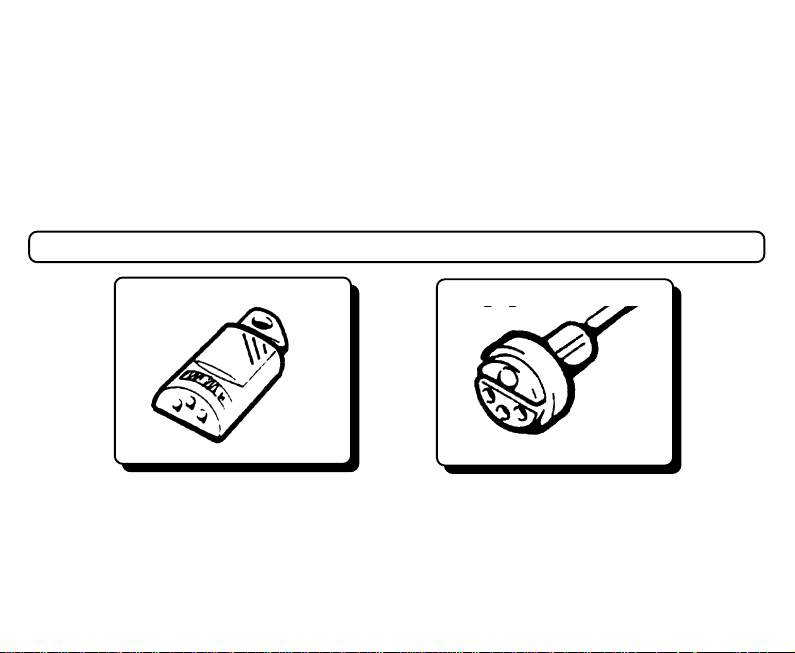
BATTERY REPLACEMENT
1 Open the remote by inserting a screwdriver between the two cases of the remote control (fig.
1). Lever to separate the two plastic cases.
2 Remove the printed circuit board (fig. 2).
3 Remove used battery (fig. 3).
4 Insert the new battery taking care to only touch the sides (not on the contact surfaces with the
metal contact and the printed circuit), into the centre compartment with the metal contacts (fig.
4).
5 Insert printed circuit board back into bottom case. Insuring printed circuit board locates prop-
erly into locators in the bottom case.
6 Refit top of case and clip together.

TECHNICAL DATA
290i2
POWER SUPPLY……………………..........................……………..............9-15V negative ground
CURRENT ABSORBED WITH ALARM ARMED (with ultrasonic)…......................................<13 mA
CURRENT ABSORBED WITH ALARM DISARMED (with ultrasonic)......................................<5 mA
PRE-ALARM TIME ............................................................................................................ 30 sec.
PRE-ALARM TIME (armed using electronic key) ............................................................... 30 sec.
DELAY TIME (after arming using electronic key) ............................................................. 10 sec.
ALARM CYCLE PERIOD .................................................................................................. 30 sec.
COURTESY LIGHT ON WHEN DISARMED ................................................................... 10 sec.
COURTESY LIGHT ON/BOOT OPENING CONTROL ................................................. Max 1 A
ADDITIONAL SIREN NEGATIVE CONTROL ................................................................. Max 1 A
POWER LOCKING SYSTEM RELAY CONTACT CAPACITY ................................................. 10 A
OPERATING TEMPERATURE ................................................................................ -40°C to 85°C
DIRECTION INDICATOR LIGHT RELAY CONTACT CAPACITY .......................................... 5+5 A
291 ADDITIONAL TECHNICAL DATA FOR 921K IMMOBILISER
POWER SUPPLY:...........................................................................................................9-15V DC
CURRENT DRAW:...............................................................................................................1.5mA
REARMING DELAY:.....................................................................................................20 seconds
RELAYS CONTACT CAPACITY (continuous):.........................................................................20 A
REMOTE CONTROL TECHNICAL DATA
Rolling code remote control at 433.92MHz, in accordance with the ETS 300-220 and ETS 300683regulations.
Lithium battery type CR2032, approximate duration 3 years with 20 operations per day.
Indication of “discharged battery” by the flashing of the red LED on the remote control.
Anti-crushing cover (resisting up to 80Kg), waterproof, with good resistance to the chemical attacks
(petrol, oil, detergents, etc.)

290i2 TEST APPROVAL NUMBERS
MIRRC Reference Number: Category 2 - 1 TU2 - 1183/1100
MIRRC Reference Number: Category L2 - 1TUL - 45/1200
291 TEST APPROVAL NUMBERS WHEN 290i2 COUPLED WITH 921K
MIRRC Reference Number: TC2 - 1200/0201
EMERGENCY PIN CODE (290I2 ONLY)
YOUR PIN CODE IS:
Note: If your pin code has not been completed by your installer please follow “AUTO-LEARNING”
procedure to obtain your pin code.

LIFETIME WARRANTY
Product warranty covers units to be free from defects in manufacture for the lifetime ownership of
the original vehicle, in accordance with the terms and conditions of this warranty document.
Any product, which is deemed to be defective, will be replaced or repaired. Accessories including
remote controls, touch keys and additional modules are guaranteed for a period of 12 months from
date of installation.
TERMS AND CONDITIONS
1. Product must be installed by an authorised qualified installer.
2. If product is transferred by an authorised installer onto another vehicle then in this case
3. Warranty is not transferable by the original customer to other owners of the product or
4. The customer must complete and return the warranty registration document within 21
5. The warranty covers product only and not the quality of the installation. The warranty for
6. All warranty claims must be directed through the original installer, accompanied by the
7. Continuance of product warranty is subject to an annual product service check for which a
8. Warranty does not cover costs incurred for breakdown assistance or vehicle recovery, due
the warranty reverts back to 2 years from the date of the original installation.
accessory.
days from date of purchase in order for the warranty to be valid.
installation is provided by the installer. We cannot be held responsible for costs arising
due to incorrect installation.
original invoice, detailing date of installation and annual service record. Failure to do this
will render the warranty invalid.
small charge may be levied by any authorised installer. Evidence of service check record
must be provided in support of warranty claims.
to product or accessory failure. Warranty does not extend to reimbursement for damage
due to defects in products or accessories.

EXCLUSIONS FROM WARRANTY
Warranty will not be valid due to the following:
1. Poor response to transmitters due to abnormally high electromagnetic interference.
2. Low battery voltage in transmitters.
3. Abuse or mistreatment of any product or accessory.
4. Loss or damage due to accident, fire, lightening, explosion, flood or water, war or civil
5. Damage caused by external electrical source or from abnormal variation or failure of
6. Failure caused by installation of accessories not approved by the product manufacturer.
7. Failure of product occurring outside Great Britain.
8. Replacement of defective parts within the guarantee period does not include consumable
9. If product is repaired by a non authorised installer the product will cease to be covered by
10. Original manufacturer negligence.
All warranties are limited to the duration of this warranty.
This is the complete warranty and no other express or implied warranty is valid. Nothing in this
warranty shall affect your statutory rights.
disturbances.
power supply.
parts or include labour.
the warranty.
CONSUMER SUMMARY
Manufacturer declines any responsibility for damage of the alarm/immobiliser and the vehicle
electrical system due to WRONG INSTALLATION OR TAMPERING.
LASERLINE SpA RESERVES THE RIGHT TO EFFECT CHANGES OF THE PRODUCT WITHOUT
FURTHER NOTICE.
NOTE

Service Inspection
1 YRS
Installer’s Stamp
Cert. No.
Reg. No.
Date.
Signature
Installer’s Stamp
Cert. No.
Reg. No.
Date.
Signature
2 YRS 3 YRS
Installer’s Stamp
Cert. No.
Reg. No.
Date.
Signature
Installer’s Stamp
Cert. No.
Reg. No.
Date.
Signature
Installer’s Stamp
Cert. No.
Reg. No.
Date.
Signature
Installer’s Stamp
Cert. No.
Reg. No.
Date.
Signature
4 YRS
Installer’s Stamp
Cert. No.
Reg. No.
Date.
Signature
PLEASE NOTE7 YRS6 YRS5 YRS
The above Service
Inspection must be
carried out in order
to ensure the
validity of the
Customer Lifetime
Warranty

CUSTOMER LIFETIME WARRANTY REGISTRATION
Alarm/Immobiliser Model No. ………...…………….............Make………………………..............…….
Accessories Fitted ………………………….............................Model………………….....................……
Date of Installation……………………………….....................Reg.No. ……….…..........……….....…….
Customer Name………………………………........................Year of Manufacture………….................
Address………………………………........................………………………………...............……………..
.................................................................................................................................................................
Postcode ………………………......................…...........Tel No. .................. ……….............……………
Installer Name ………………….......…………….........Account No. …...................……………....……..
Address………………………………………………………………………………….........………………...
Postcode …………………………………………….........Tel No. ……................…..................…………
I have read and understood the terms and conditions of the Customer Lifetime Warranty.
Customer Signature.......................................................................
FAILURE TO COMPLETE AND RETURN THIS CARD WILL RESULT IN YOUR WARRANTY
IMPORTANT NOTE
BECOMING VOID.

Return to:
Laserline Direct Limited
33, Craven Court
Winwick Quay
Warrington
Cheshire
WA2 8QU


Dealer Stamp
Our commissioned Sales and Support Agents in the UK areOur commissioned Sales and Support Agents in the UK are
Our commissioned Sales and Support Agents in the UK are
Our commissioned Sales and Support Agents in the UK areOur commissioned Sales and Support Agents in the UK are
33, Craven Court - Winwick Quay - Warrington - Cheshire WA2 8QU
Laserline Direct Limited
 Loading...