

GB
270UK/278UK INSURANCE APPROVED ALARM
(ORIGINAL REMOTE CONTROL UPGRADE) USER
GUIDE
ISUT270-278UK.p6512/05/2006, 10.241
®
CAR ALARM SYSTEMS

270UK/278UK COMPACT ALARM SYSTEM FOR ALL CARS/LIGHT COMMERCIAL VEHICLES
This system is manufactured from the highest quality components to ensure a long trouble free operating life and comply with the British insurance industry’s criteria for vehicle security for Category 2 à 1 (L2 à 1) (AFTERMARKET SYSTEMS) [Utilising the original
equipment remote tested to Issue 2 Criteria] product, as evaluated by Thatcham
(MIRRC).
Note: Category 2 à 1 (L2 à 1) product – 270/278 alarm system is only to be fitted in conjunction
with a Category 2 (L2) immobiliser to obtain Category 1 status for the vehicle security.
The 270/278 Category 2 - 1 alarm is for vehicles equipped with a 12v negative earth electrical
system.
These instructions are intended to familiarise you with their very simple operation.
THIS PRODUCT MUST BE INSTALLED
BY SKILLED AND QUALIFIED PERSONNEL
WARNING
ALARMS MUST NOT BE STEAM CLEANED OR PRESSURE WASHED.
BEFORE CARRYING OUT ANY ELECTRICAL WORK ON THE VEHICLE ISOLATE
THE SYSTEM BY REMOVING SYSTEM FUSE/VEHICLE BATTERY OR DAMAGE
TO THE ALARM MAY RESULT!
ISUT270-278UK.p6512/05/2006, 10.242

ENGLISH
1 - INDEX
1) Index.........................................................................................................................................3
2) Introduction...............................................................................................................................4
3) 270 System Components.........................................................................................................4
3) 278 System Components.........................................................................................................5
4) Alarm system Operation:.........................................................................................................6
4.1 - Alarm System Arming/Disarming....................................................................................6
4.2 - Alarm Condition...............................................................................................................6
4.3 - Alarm Cycle Limitation.....................................................................................................6
4.4 - Sensor Self-Testing............................................................................................................7
4.5 - Alarm Trigger Signalling...................................................................................................8
4.6 - Alarm Trigger History.......................................................................................................8
5) Problem Solving........................................................................................................................9
6) Optional Feature......................................................................................................................9
6.1 - Accidental Disarming.......................................................................................................9
6.2 - Passive Arming..............................................................................................................10
6.3 - Additional Siren..............................................................................................................10
7) Feature Exclusions..................................................................................................................10
8) Garage Function.....................................................................................................................11
9) Disarm Using Your Emergency Pin Code................................................................................ 12
9.1- How to Know Your Emergency Pin Code......................................................................... 14
10) Self-Learning Of A New Electronic Key.................................................................................16
11) Homologations.................................................................................................................... 17
12) Technical Data..................................................................................................................... 18
13) Lifetime Warranty..................................................................................................................18
14) Service Inspection.................................................................................................................20
15) Customer Lifetime Warranty Registration..............................................................................21
17) Test Approval Number..........................................................................................................23
17) Emergency Pin Code.............................................................................................................23
ISUT270-278UK.p6512/05/2006, 10.243
pag. 3
ENGLISH
2 - INTRODUCTION
This alarm system is exclusively a deterrent against possible theft.
In no way can it be considered as an actual insurance against theft.
The manufacturer declines any liability for faults or anomalies in the alarm system, in its accessories or in the vehicles’s electric equipment due to incorrect installation or unobservant of specified
features/standards.
The manufacturer reserves the right to make any changes, whenever they should be necessary,
without giving prior notice.
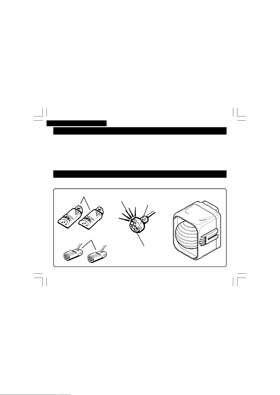
3 - 270 SYSTEM COMPONENTS
Your alarm system consists of the following items:
Electronic keys
Ultrasonic detectors
pag. 4
ISUT270-278UK.p6512/05/2006, 10.244
Red LED
Central unit
Receptacle
Socket
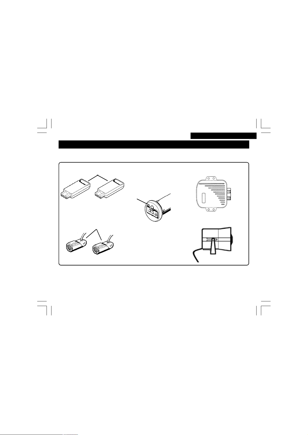
3 - 278 SYSTEM COMPONENTS
Your alarm system consists of the following items:
ENGLISH
Electronic keys
Alarm unit
Receptacle
Red LED
Ultrasonic detectors
Note: The 270 alarm sytem is a compact unit where the alarm and siren are combind, the 278
alarm system is a modular unit where the alarm and siren are seperate. The modular system is
normally used when there is limited space in the engine compart.
KEY * Optional. ** Vehicle dependent. *** Key operated deadlocking may disarm the alarm.
ISUT270-278UK.p6512/05/2006, 10.245
Electronic socket
908 Siren
pag. 5

ENGLISH
4 - ALARM SYSTEM OPERATION
4.1 - ALARM SYSTEM ARMING/DISARMIG
To arm the alarm, press the lock or deadlock** button on the vehicles original remote control; direction
indicators lights flash twice* and the alarm may give two acoustic tones* to indicate that the system is
now armed.
Once armed, the alarm system will operate the comfort closure**/window closure* if these functions
have been incorporated.
The red LED in the receptacle will remain on for 30 seconds (pre-alarm time), then begin to flash to
indicate the alarm system is fully armed.
To disarm the alarm, press the unlock button on the vehicle original remote control or insert a valid
electronic key into the receptacle socket; direction indicators lights will flash once* and the alarm may
give one acoustic tone* to indicate that the alarm system is now disarmed.
Ø at least 3 seconds should pass between locking/unlocking the vehicle, otherwise you may fail
to transmit the new arm/disarm status.
Ø it is possible to use the electronic key to disarm the alarm but not to arm it.
Ø comfort closure is a feature that may already be incorporated into the original remote control of
the vehicle. Check vehicle user guide for operation.
4.2 - ALARM CONDITION
When fully armed if a sensor is activated, the system will generate an alarm condition: direction
indicators flash and the siren sounds for 30 seconds (alarm cycle). At the end of the alarm cycle, if the
same sensor is still activated, the alarm will generate an alarm cycle again.
4.3 - ALARM CYCLE LIMITATION
The system will automatically exclude the sensor, which has generated 8 alarm cycles in one
armed period. All the other sensors will continue to protect the vehicle. The maximum number of
pag. 6
ISUT270-278UK.p6512/05/2006, 10.246

ENGLISH
alarm cycles for every sensor is 8, except for power supply interruption sensor (10 alarm cycles).
Note: If a sensor continues to remain activated whilst in the pre-alarm time, the system will automatically exclude this sensor at the end of the pre-alarm time and not generate an alarm condition.
When the alarm system is next disarmed a shorter than normal flash of the direction indicator
lights and an accoustic tone will be produced to indicate that a sensor was activated whilst arming.
To identify the sensor that was activated, consult the “ ALARM TRIGGER SIGNALLING”
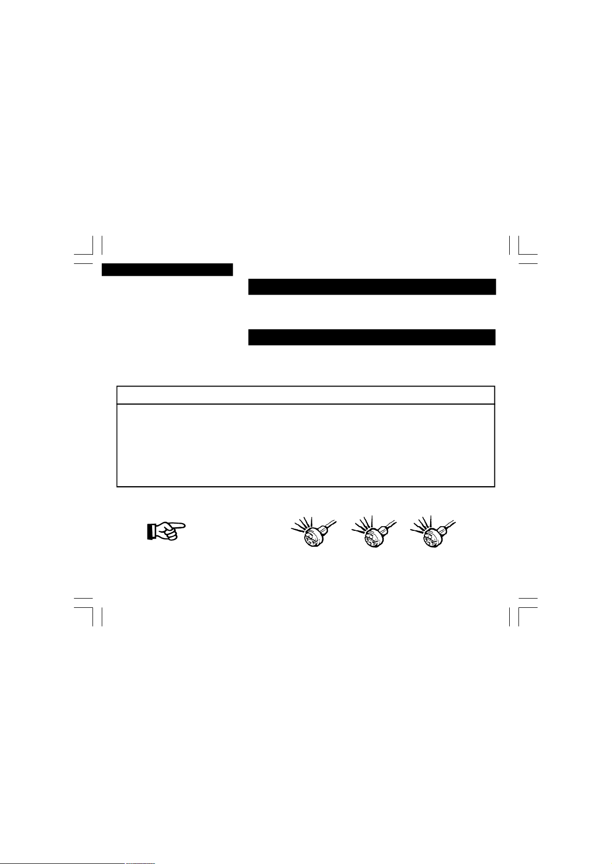
4.4 - SENSOR SELF-TESTING
This facility confirms the correct operation of interior/doors/boot/bonnet detection circuits. This is
indicated by a series of audible tones/illumination of the direction indicators and a series of flashing of the dashboard LED, when one of the circuits is triggered within the pre-alarm time. To self
test the detection circuits:
DOORS/BOOT/BONNET DETECTION CIRCUITS
1Arm the alarm with the remote control.
2Unlock the vehicle manually with a key***.
3Within the first 30 seconds of arming the alarm open and close all doors/boot/bonnet. The
alarm will respond with 3 audible tones, 3 flashes of the direction indicators and the LED will
go out. If vehicle is fitted with a courtesy light delay system, you may have to wait for the courtesy light to go out before testing the next doors/boot/bonnet detection circuits.
INTERIOR DETECTION CIRCUIT (Ultrasonic/microwave sensors)
1 Sit inside the vehicle.
2Arm the alarm with the remote control.
3Within the first 30 seconds of arming the alarm, create movement in front of the interior sen-
sors (ultrasonics - normally mounted at top of windscreen). The alarm will respond with 3 audible tones, 1 flash of the direction indicators and the LED will go out.
Ø 4 seconds must pass between each detection circuit tested before the next self-test signals will
be produced.
Ø turning the ignition key on or disconnecting the power supply to the alarm system whilst in the
pre alarm time or when fully armed will cause an immediate alarm condition.
pag. 7
ISUT270-278UK.p6512/05/2006, 10.247
ENGLISH
4.5 - ALARM TRIGGER SIGNALLING
If an alarm condition occurred whilst you were not present, the alarm will signal it through a brief visual
and acoustic disarm signal instead of a long disarm signal.
You will be able to identify the exact alarm cause thanks to the “ ALARM TRIGGER HISTORY” function.
4.6 - ALARM TRIGGER HISTORY
It is possible to know the last 5 alarm triggers which have occurred by turning on the ignition key 3
times within 5 seconds while the alarm system is disarmed.
Each alarm cause is associated to an identification flash code:
FLASH CODES
2 FLASHES/PAUSE: the ULTRASONIC sensor generated an alarm condition
3 FLASHES/PAUSE: the DOOR/HATCH sensor generated an alarm condition
4 FLASHES/PAUSE: the BONNET sensor generated an alarm condition
5 FLASHES/PAUSE: the IGNITION KEY sensor generated an alarm condition
6 FLASHES/PAUSE: the POWER SUPPLY (270 only) sensor generated an alarm condition
7 FLASHES/PAUSE: the BOOT/ADDITIONAL sensor generated an alarm condition
The alarm cause is displayed by the LED flashing as many times as the alarm identification flash code,
e.g.:
ALARM CAUSE
Door-hatch
opening
alarm
At first the most recent alarm identification flash code will be displayed, followed by a short pause
and then the second-last and so on until the fifth one; the display ends automatically and an
acoustic tone will be heard.
pag. 8
ISUT270-278UK.p6512/05/2006, 10.248
=

ENGLISH
Note: The trigger history will not be cleared if the power to the alarm system is disconnected.
In case the trigger memory contains less than 5 triggers, the procedure will automatically end immediately after the display of the oldest flash code.
5 - PROBLEM SOLVING
If you find you have to get closer to the vehicle to unlock/disarm the alarm, this is normally a indication that the original remote control batteries may need replacing. Refer to vehicle’s user guide
for replacing the remote batteries.
If your alarm sounds for no apparent reason, please refer to the “ALARM TRIGGER HISTORY” for
possible condition. Possible causes of the alarm condition could be:
-Vehicle has been tampered with.
-Windows/sunroof are not fully closed.
-Doors/boot/bonnet are not fully closed.
-Check that the air vents have not been left open. Air movement within the vehicle may trigger
your alarm.
-Check the doors/boot/bonnet contact switches operate correctly.
-Articles inside the vehicle are moving e.g. jacket, hanging toys or accessories.
6 - OPTIONAL FEATURES
6.1 - ACCIDENTAL DISARMING*
On your return to the vehicle, if you disarm the system but do not enter the vehicle (doors/bonnet/
boot) within 40 seconds, the alarm will automatically re-arm itself. Useful if you accidentally disarm the alarm from a distance without knowing. This function is cancelled if you enter the vehicle
(doors/bonnet/boot) within 40 seconds from when the alarm is disarmed. Please ensure you lock
the doors manually!
pag. 9
ISUT270-278UK.p6512/05/2006, 10.249

ENGLISH
Note: Some vehicles may have a similar locking feature, where if the vehicle is unlocked and then
not entered, the vehicle locking system re-locks the vehicle. In this case the alarm may fully re-arm
activating comfort closing*/window closing*/additional sensor* and the ultrasonic/microwave sensor*.
6.2 - PASSIVE ARMING*
This function allows the alarm to be armed automatically when you switch off the ignition and exit
the vehicle, without using the original remote control. 13 seconds after the last door is closed/or
13 seconds after the courtesy lights go out the alarm will arm. Please ensure you lock the doors
manually!
To disarm the alarm if it as been armed by one of the above features:
- original remote control – in this case you may need to prompt the vehicle for locking and then
prompt it again for unlocking, in order for the alarm to be re-synchronised again with the vehicle
lock status;
- emergency electronic key – enter the vehicle, the alarm generated by a door opening will be
delayed for 5 seconds, to allow the electronic key to be inserted into the receptacle socket.
Ø When armed through these functions the alarm will not activate the comfort closing*/window
closing*/additional sensor* and the ultrasonic/microwave sensor*.
Ø Accidental Disarming feature may not be available on vehicles where the original remote lock-
ing puts on the courtesy lights when unlocking.
6.3 - ADDITIONAL SIREN*
This function allows the alarm to be connected to an additional siren/vehicle horn/paging system
and can be programmed to obtain a continuous or intermittent output for the entire alarm cycle.
7 - FEATURE EXCLUSIONS
The following features may be disabled:
pag. 10
ISUT270-278UK.p6512/05/2006, 10.2410

ENGLISH
Ultrasonic exclusion (e.g. if you want to use the alarm whilst keeping vehicle windows open);
Siren exclusion (e.g. if your vehicle is parked in a hospital car park, ferries, skiing resort etc.);
Acoustic tones exclusion ( e.g.no arm/disarm tones, no feature warning acoustic signals).
To disable any of the features, insert and keep inserted an electronic key into the receptacle socket;
Πto disable the ultrasonic detectors for one arming cycle: remove the electronic key after the LED
has flashed once, accompanied by a acoustic tone;
• to disable the siren for one arming cycle: remove the electronic key after the LED has flashed
twice in succession, accompanied by two acoustic tones.
Ž to toggle OFF the acoustic tones: remove the electronic key after the LED has flashed three in
succession, accompanied by three acoustic tones.To toggle ON the acoustic tones: remove the
electronic key after the LED has flashed three in succession (no acoustic tones).
Ultrasonic and Siren exclusion will work normally after you disarm the alarm.
Disabling the ultrasonic detector causes the optional window closing/optional sensor to be disabled and therefore all the associated functions.
Disabling the siren does not disable the optional siren output.
8 - GARAGE FUNCTION
This function allows the alarm system to be excluded temporarily, in order to let you leave the vehicle
in a workshop for repairs or maintenance.
When you receive the vehicle back, you can exit this mode and restore the alarm back to its normal
functions.
To enable garage function:
Πinsert and hold an electronic key into the receptacle socket;
• wait until the LED flashes four times in succession, accompanied by four acoustic tones;
Ž continue to hold the electronic key in the receptacle socket for a further 3 seconds until garage
mode is signalled by a short flash of the direction indicator lights and a short acoustic tone;
pag. 11
ISUT270-278UK.p6512/05/2006, 10.2411

ENGLISH
• now remove the electronic key.
With garage function enabled the alarm will flash the red LED in the receptacle every 15 seconds to
indicate garage mode. If the optional immobilisation relay is fitted to the vehicle with the optional
passive functions enabled, these function will be disabled allowing the vehicle to be driven.
To disable the garage function:
Πturn on the vehicles ignition key and keep it turned on;
• insert an electronic key into the receptacle socket;
Ž the exit from the garage mode will be signalled by a long flash of the direction indicator lights
and a long acoustic tone;
• remove the electronic key.
9 - DISARM USING YOUR EMERGENCY PIN CODE
If your original remote control/electronic key does not work correctly or has been lost, to disarm
the alarm system and enter the alarm into garage function (see section 8) you must insert the
“emergency pin code” by doing the following:
Œ With the alarm armed, activate the siren by opening the door on the driver’s side;
• Enter the vehicle. The alarm will stop sounding after 30 seconds and then the LED installed on
the dashboard will illuminate for 5 seconds. Within the 5 seconds, turn the ignition key ON
and OFF for 1 second;
Ž The LED in the receptacle will start to flash and the alarm is ready to accept the Pin Code. If
not interrupted, the LED will flash 10 times. Wait for the flashes corresponding to each digit of
your Pin Code to be displayed, then turn the ignition key ON and OFF for 1 second only after
the LED is off. Read Pin Code at the end of these instructions from left to right. See the following example:
pag. 12
ISUT270-278UK.p6512/05/2006, 10.2412

the pin code to be inserted is 5 6 0 5 4.
ENGLISH
5
=
6
=
0
=
5
=
4
=
Key
LED Flashes
Acoustic Tones
Key
On
ISUT270-278UK.p6512/05/2006, 10.2413
Ignition Key
On
Key
On
Key
On
Key
On
Key
On
Key
On
Pin code entered correctly alarm
enters garage function without
accoustic tones or flashing the
direction indicator lights
Pin code entered incorrectly
alarm will stay armed
pause
pause
pause
pause
ALARM DISARMED
ALARM ARMED
pag. 13

ENGLISH
EXAMPLE: the pin code to be inserted is 5 6 0 5 4.
First digit 5 - Wait 5 flashes/acoustic tones for the first digit. After the fifth flash/acoustic tone has
been completed and the LED has turned OFF, immediately turn ON the ignition key for 1 second.
Turn the ignition OFF and after a pause, the LED/acoustic tones will start again for the next digit of
the Pin Code; Second digit 6 - Wait 6 flashes/acoustic tones for the second digit. After the sixth
flash/acoustic tone has been completed and the LED has turned OFF, immediately turn ON the ignition key for 1 second. Turn the ignition OFF and after a pause, the LED/acoustic tones will start
again for the next digit of the Pin Code; Third digit 0 - For the 0 digit, the flashes/acoustic tones to
be completed are 10. Continue until all the digits have been displayed and inputted correctly. If the
code inserted is correct, the alarm will automatically disarm and enter garage function, without a
short flash of the direction indicator lights and a short acoustic tone. If the code is incorrect, the
alarm will stay armed and sound the siren if triggered again.
Important: to ensure the security procedure, the alarm system does not give a indication
of an incorrect code inputted.
9.1 - HOW TO KNOW YOUR EMERGENCY PIN CODE
To display your personal 5 -digit emergency pin code with which you can perform an emergency
disarming of your alarm system.
Œ Open the door on the driver’s side;
• Turn the ignition key On;
Ž Insert and keep inserted an electronic key into the receptacle socket;
• Now turn Off the ignition key;
• Remove the electronic key from the receptacle socket.
The red LED in the receptacle will flash 10 times and remain on for 10 seconds, the LED will go out
and the alarm will start to flash the LED accompanied with acoustic tones a number of times equal
to the number related to the first digit of your emergency pin code (see the example below).
pag. 14
ISUT270-278UK.p6512/05/2006, 10.2414

ENGLISH
the Pin Code to note at the end of these instructions would be 5 6 0 5 4.
5
6
10
5
4
=
=
=
=
=
pause
pause
pause
pause
exit
Key
LED Flashes
It is imperative to note on a piece of paper this pin code, if it is different from the original pin code
displayed in the rear of these instructions. This pin code must then be stored in a secure location.
If you intend to leave these instructions in the vehicle, the pin code in the back of these instructions
should be removed for safe keeping.
This pin code is derived from the first electronic key memorised when you self-learn the electronic
keys. If you want to change the pin code from the original code, you may have to follow the selflearning procedure more than once alternating the first electronic key until a new pin code is given.
Acoustic Tones
Note:
pag. 15
ISUT270-278UK.p6512/05/2006, 10.2415

ENGLISH
10 - SELF-LEARNING OF A NEW ELECTRONIC KEY
The self-learning function allows you to program new electronic keys or cancel electronic keys.
To carry out the self-learning procedure, an original functioning electric key must be available.
Then do the following:
Œ Open the door on the driver’s side;
• Turn the ignition key ON;
Ž Insert and keep inserted an electronic key into the receptacle socket;
• Now turn off the ignition key;
• Remove the electronic key from the receptacle socket. The red LED in the receptacle will flash
10 times and remain on, indicating the self-learning is activated;
‘ At this point, insert the electronic keys into the receptacle socket, that you want to store into
the alarms memory. The red LED will turn off briefly for each electronic key that has been
programmed into the alarm memory;
’ To complete the self-learning procedure either; turn the ignition ON to exit the function or
wait 10 seconds for the LED to go out and then start to flash the emergency pin code (see
section “ How to Know Your Emergency Pin Code” ).
Ø You should allow no more than 10 seconds between key insertions.
Ø You can program a maximum of 4 electronic keys.
Ø The electronic keys not programmed during the last self-learning session will be automatically
cancelled by the alarm memory.
Ø If all electronic keys are lost, contact your nearest area dealer.
KEY * Optional. ** Vehicle dependent. *** Key operated deadlocking may disarm the alarm.
pag. 16
ISUT270-278UK.p6512/05/2006, 10.2416

ENGLISH
11 - HOMOLOGATIONS
This product complies with the requirements of applicable European directives.
You will find a label on the alarm unit stating the homologation number, obtained according to the
European directive 95/56/CE.
product
homologation mark
manufacturer
XXX
XXX
XX xxxx
XX XXX
XXXXXXXX XXV
XX-XXXXXX
e 12
12 - TECHNICAL DATA
270/278
POWER SUPPLY............................................................................................9-15V negative ground
CURRENT ABSORBED WITH ALARM ARMED (with ultrasonic)................................................<13 mA
CURRENT ABSORBED WITH ALARM DISARMED (with ultrasonic).............................................<5 mA
PRE-ALARM TIME...................................................................................................................30 sec.
DELAY ENTRY TIME (armed by passive features)......................................................................5 sec.
ALARM CYCLE PERIOD...........................................................................................................30 sec.
ADDITIONAL SIREN NEGATIVE CONTROL............................................................................Max 1 A
OPERATING TEMPERATURE.........................................................................................-40°C to 85°C
DIRECTION INDICATOR LIGHT RELAY CONTACT CAPACITY......................................................5+5 A
908 SIREN
POWER SUPPLY............................................................................................9-15V negative ground
CURRENT ABSORBED WHEN CHARGING..............................................................................<25 mA
CURRENT ABSORBED WHEN FULLY CHARGED....................................................................<2.5 mA
ISUT270-278UK.p6512/05/2006, 10.2417
pag. 17

ENGLISH
13 - LIFETIME WARRANTY
Product warranty covers units to be free from defects in manufacture for the lifetime ownership of
the original vehicle, in accordance with the terms and conditions of this warranty document.
Any product, which is deemed to be defective, will be replaced or repaired. Accessories including
electronic keys and additional modules are guaranteed for a period of 12 months from date of
installation.
TERMS AND CONDITIONS
1.Product must be installed by an authorised qualified installer.
2.If product is transferred by an authorised installer onto another vehicle then in this case
3.Warranty is not transferable by the original customer to other owners of the product or
4.The customer must complete and return the warranty registration document within 21
5.The warranty covers product only and not the quality of the installation. The warranty for
6.All warranty claims must be directed through the original installer, accompanied by the
7.Continuance of product warranty is subject to an annual product service inspection for
8.Warranty does not cover costs incurred for breakdown assistance or vehicle recovery, due
pag. 18
the warranty reverts back to 2 years from the date of the original installation.
accessory.
days from date of purchase in order for the warranty to be valid.
installation is provided by the installer. We cannot be held responsible for costs arising
due to incorrect installation.
original invoice, detailing date of installation and annual service record. Failure to do this
will render the warranty invalid.
which a small charge may be levied by any authorised installer. Evidence of service
inspection record must be provided in support of warranty claims.
to product or accessory failure. Warranty does not extend to reimbursement for damage
due to defects in products or accessories.
ISUT270-278UK.p6512/05/2006, 10.2418

ENGLISH
EXCLUSIONS FROM WARRANTY
Warranty will not be valid due to the following:
1.Poor response to transmitters due to abnormally high electromagnetic interference.
2.Low battery voltage in transmitters.
3.Abuse or mistreatment of any product or accessory.
4.Loss or damage due to accident, fire, lightening, explosion, flood or water, war or civil
disturbances.
5.Damage caused by external electrical source or from abnormal variation or failure of
power supply.
6.Failure caused by installation of accessories not approved by the product manufacturer.
7.Failure of product occurring outside Great Britain.
8.Replacement of defective parts within the guarantee period does not include consumable
parts or include labour.
9.If product is repaired by a non authorised installer the product will cease to be covered by
the warranty.
10.Original manufacturer negligence.
CONSUMER SUMMARY
All warranties are limited to the duration of this warranty.
This is the complete warranty and no other express or implied warranty is valid. Nothing in this
warranty shall affect your statutory rights.
Manufacturer declines any responsibility for damage of the alarm/immobiliser and the vehicle
NOTE
electrical system due to WRONG INSTALLATION OR TAMPERING.
LASERLINE SpA RESERVES THE RIGHT TO EFFECT CHANGES OF THE PRODUCT WITHOUT
FURTHER NOTICE.
ISUT270-278UK.p6512/05/2006, 10.2419
pag. 19

ENGLISH
14 - SERVICE INSPECTION
1 YRS
Installer’s Stamp
Cert. No.
Reg. No.
Date.
Signature
Installer’s Stamp
Cert. No.
Reg. No.
Date.
Signature
pag. 20
ISUT270-278UK.p6512/05/2006, 10.2420
Installer’s Stamp
Cert. No.
Reg. No.
Date.
Signature
Installer’s Stamp
Cert. No.
Reg. No.
Date.
Signature
2 YRS3 YRS
Installer’s Stamp
Cert. No.
Reg. No.
Date.
Signature
Installer’s Stamp
Cert. No.
Reg. No.
Date.
Signature
4 YRS
Installer’s Stamp
Cert. No.
Reg. No.
Date.
Signature
PLEASE NOTE7 YRS6 YRS5 YRS
The above Service
Inspection must be
carried out in order
to ensure the
validity of the
Customer Lifetime
Warranty

ENGLISH
15 - CUSTOMER LIFETIME WARRANTY REGISTRATION
Alarm/Immobiliser Model No. ………...…………….............Make………………………..............…….
Accessories Fitted ………………………….............................Model………………….....................……
Date of Installation……………………………….....................Reg.No. ……….…..........……….....…….
Customer Name………………………………........................Year of Manufacture………….................
Address………………………………........................………………………………...............……………..
.................................................................................................................................................................
Postcode ………………………......................…...........Tel No. .................. ……….............……………
Installer Name ………………….......…………….........Account No. …...................……………....……..
Address………………………………………………………………………………….........………………...
Postcode …………………………………………….........Tel No. ……................…..................…………
I have read and understood the terms and conditions of the Customer Lifetime Warranty.
Customer Signature.......................................................................
FAILURE TO COMPLETE AND RETURN THIS CARD WILL RESULT IN YOUR WARRANTY
IMPORTANT NOTE
BECOMING VOID.
ISUT270-278UK.p6512/05/2006, 10.2421
pag. 21

ENGLISH
Return to:
Laserline Direct Limited
33, Craven Court
Winwick Quay
Warrington
Cheshire
WA2 8QU
pag. 22
ISUT270-278UK.p6512/05/2006, 10.2422

ENGLISH
16 - 270UK/278UK TEST APPROVAL NUMBER
270UK - MIRRC Reference Number: Category 2 - 1 TU2-1245/0302
270UK - MIRRC Reference Number: Category L2 - 1 TUL1-75/0302
278UK - MIRRC Reference Number: Category 2 - 1 TU2-1369/0506
278UK - MIRRC Reference Number: Category L2 - 1 TUL1-135/0506
17 - EMERGENCY PIN CODE
YOUR PIN CODE IS:
Note: If your pin code has not been completed by your installer please follow “HOW TO KNOW
YOUR EMERGENCY PIN CODE” procedure to obtain your pin code.
NOTES
ISUT270-278UK.p6512/05/2006, 10.2423
pag. 23

Dealer Stamp
Our commissioned Sales and Support Agents in the UK are
33, Craven Court - Winwick Quay - Warrington - Cheshire WA2 8QU
ISUT270-278UK.p6512/05/2006, 10.2424
Laserline Direct Limited
cod. ISUT270-278UK
FILENAME: ISUT270-278UK.P65
 Loading...