

Laserex Tango LT5106-T, Solo LT5106-S, Ultra Q LQP 3106-U Installation, Commissioning And Service Manual
Page 1

Ophthalmic Nd:YAG
Lasers
Installation, Commissioning
and
Service Manual
M Devices Group
Marlborough House
Riding Street
Southport PR8 1EW
United Kingdom.
93/42/EEC
0805
Telephone: +44-1-704 544 944
Facsimile: +44-1-704 544 050
Page 2

Page 3

This service manual describes the installation, commissioning and maintenance of the Laserex
Tango LT5106-T, Ultra Q LQP 3106-U and Solo LT5106-S Nd:YAG lasers.
Terms used in this Service Manual which are known, or suspected, to be trademarks are listed
below. Use of a term in this service manual should not be regarded as affecting the validity of
any trademark or service mark.
Tango, Ultra Q, Solo, Access and Mobile are registered trademarks of Ellex Medical Pty Ltd
Laserex is a registered trademark of Ellex Medical Pty Ltd
Kodak is a trademark of Eastman Kodak, USA
Condor is a trademark of Condor D.C. Power Supplies, Inc, USA
Every effort has been made to ensure that the information in this manual is
accurate, but the information, illustrations, tables, drawings, and specifications
contained in the document are subject to change without notice.
If you have any questions or encounter difficulties do not hesitate to contact your local
Authorised Distributor or:
Product Manager
Ellex Medical Pty Ltd
82 Gilbert Street
Adelaide, SA 5000
AUSTRALIA
Postal Address:
P.O. Box 6239, Halifax Street
Adelaide, SA 5000
AUSTRALIA
Phone (Reception): 61 8 8104 5200
Fax (Reception): 61 8 8104 5210
This product was designed and manufactured in Australia by
Ellex Medical Pty. Ltd.
This service manual is Ellex P/N 8436016 Issue 2.0.
Copyright © 2004, Ellex Medical Pty. Ltd
This service manual contains confidential and proprietary information of Ellex Medical Pty Ltd
and may not be reproduced in whole or part without their written approval.
Page 4

Caution
Use of controls or adjustments, or performance of procedures other
than those specified herein may result in hazardous radiation exposure.
We strongly recommend that you read and understand this Service
Manual in its entirety before using or servicing the product.
Cautions
Use of controls or adjustments, or performance of procedures other
than those specified herein may result in hazardous radiation exposure.
We strongly recommend that this manual be read in its entirety before
using the product.
Cautions
This service manual is intended for the use of fully trained and qualified
Laserex service personnel ONLY. Do not service this equipment unless
you have been trained on this instrument.
Follow all laser and electrical safety precautions when servicing this
equipment.
Page 5

ABOUT THIS MANUAL ..........................................................................................................................................IX
CHAPTER 1
INTRODUCTION............................................................................................................................. 1-1
1.1 Introducing the Tango, Ultra Q and Solo............................................................................1-1
1.2 Components...............................................................................................................................1-3
1.3 Theory of operation..................................................................................................................1-3
1.4 What is a laser?..........................................................................................................................1-4
CHAPTER 2
SAFETY........................................................................................................................................... 2-1
2.1 Safety classification and warnings.........................................................................................2-1
2.2 Safety features............................................................................................................................2-4
2.3 Safety precautions.....................................................................................................................2-8
2.4 Electrical safety precautions ...................................................................................................2-9
2.5 Safety labels............................................................................................................................. 2-10
2.6 Calculating nominal ocular hazard distance.................................................................... 2-12
C ONTENTS
CHAPTER 3
FUNCTIONAL DESCRIPTION............................................................................................................ 3-1
3.1 Laser and optical systems........................................................................................................3-1
3.2 Laser head components ..........................................................................................................3-2
3.3 Power supply console components .................................................................................. 3-15
3.4 Table and stand components.............................................................................................. 3-16
3.5 Controls and features............................................................................................................ 3-16
CHAPTER 4
ELECTRICAL SYSTEM........................................................................................................................ 4-1
4.1 Electrical system description...................................................................................................4-1
4.2 Start-up and initialisation processes......................................................................................4-3
4.3 Firing processes .........................................................................................................................4-4
Tango, Ultra Q and Solo Service Manual i
Issue 2.0
Page 6

Contents
CHAPTER 5
INSTALLATION AND COMMISSIONING............................................................................................5-1
5.1 Installation procedures ............................................................................................................ 5-1
5.2 Tools and materials................................................................................................................... 5-1
5.3 Unpacking .................................................................................................................................. 5-2
5.4 Stages in assembly.................................................................................................................... 5-2
5.5 Assembling ................................................................................................................................. 5-4
5.6 Testing the system ..................................................................................................................5-10
5.8 Commissioning checks..........................................................................................................5-10
CHAPTER 6
ALIGNMENT AND CALIBRATION......................................................................................................6-1
6.1 Steps in alignment and calibration........................................................................................ 6-1
6.2 Equipment required..................................................................................................................6-2
6.3 Optical alignment ..................................................................................................................... 6-2
6.4 Calibration ..................................................................................................................................6-4
6.5 Setting up the attenuator ......................................................................................................6-10
6.6 Checking aiming accuracy....................................................................................................6-13
6.7 Aligning the YAG treatment beam (Tango/Ultra Q) ......................................................6-16
6.8 Aligning the SLT treatment beam (Tango/Solo)...............................................................6-25
6.9 Calibration verification test...................................................................................................6-30
CHAPTER 7
OPERATION ...................................................................................................................................7-1
7.1 Preparing the instrument — cleaning and disinfection ..................................................... 7-1
7.2 Pre-start checks.......................................................................................................................... 7-1
7.3 Starting up .................................................................................................................................. 7-1
7.4 Using as a slit lamp................................................................................................................... 7-2
7.5 Operating states........................................................................................................................ 7-3
7.6 Preparing for operation ........................................................................................................... 7-3
7.7 Operating the YAG treatment beam (Tango/ Ultra Q) ................................................... 7-7
7.8 Operating the SLT treatment beam (Tango/Solo)............................................................. 7-9
7.9 Shutting down .........................................................................................................................7-10
7.10 Moving the instrument ..........................................................................................................7-10
CHAPTER 8
ROUTINE CARE...............................................................................................................................8-1
8.1 Introduction................................................................................................................................ 8-1
8.2 Routine care schedule ............................................................................................................. 8-1
8.3 Cleaning the system .................................................................................................................8-2
8.4 Cleaning the external optics................................................................................................... 8-3
8.5 Inspecting the safety filters (Tango/Solo) ............................................................................ 8-4
ii Tango, Ultra Q and Solo Service Manual
Issue 2.0
Page 7

Contents
CHAPTER 9
MAINTENANCE PROCEDURES ......................................................................................................... 9-1
9.1 Routine stand testing................................................................................................................9-1
9.2 Verifying correct performance...............................................................................................9-1
9.3 Checking aiming accuracy......................................................................................................9-2
9.4 Replacing the slit lamp halogen lamp ..................................................................................9-3
9.5 Replacing fuses.......................................................................................................................... 9-3
9.6 Checking the alignment...........................................................................................................9-4
9.7 Checking the calibration .........................................................................................................9-4
9.8 Checking ground resistance ...................................................................................................9-4
9.9 Transportation............................................................................................................................9-4
9.10 Product lifetime .........................................................................................................................9-5
9.11 Product disposal........................................................................................................................9-6
CHAPTER 10
FAULT FINDING............................................................................................................................10-1
10.1 Troubleshooting table ........................................................................................................... 10-1
10.2 Error codes............................................................................................................................... 10-3
10.3 Engineering and service modes .......................................................................................... 10-4
10.4 Calibrating the diode aiming modules ............................................................................10-10
10.5 Calibrating energy curves...................................................................................................10-12
10.6 Checking the energy monitor calibrations..................................................................... 10-14
10.7 Determining the YAG operating voltages (Tango/Ultra Q)....................................... 10-16
10.8 Aligning the KTP crystal (Tango/Solo)............................................................................. 10-17
10.9 Viewing and editing constants.......................................................................................... 10-20
CHAPTER 11
ERROR CODES .............................................................................................................................11-1
CHAPTER 12
FIELD REPAIR AND MODULE REPLACEMENT...................................................................................12-1
12.1 Modules ................................................................................................................................... 12-1
12.2 Laser head modules............................................................................................................... 12-5
12.3 Table modules.......................................................................................................................12-37
CHAPTER 13
SPECIFICATIONS...........................................................................................................................13-1
13.1 System specifications ............................................................................................................ 13-1
13.2 YAG treatment laser specifications (Tango/Ultra Q)..................................................... 13-2
13.3 SLT treatment laser specifications (Tango/Solo)............................................................. 13-2
13.4 Aiming lasers ........................................................................................................................... 13-3
13.5 Slit lamp delivery system ...................................................................................................... 13-3
13.6 Power supplies........................................................................................................................ 13-4
13.7 Accessories.............................................................................................................................. 13-5
Tango, Ultra Q and Solo Service Manual iii
Issue 2.0
Page 8

Contents
APPENDIX A
SPARE PARTS LIST AND SERVICE TOOL KIT....................................................................................... A-1
APPENDIX B
DRAWINGS ....................................................................................................................................B-1
APPENDIX C
PARAMETER LISTING ...................................................................................................................... C-1
APPENDIX D
SERVICE BULLETINS........................................................................................................................ D-1
APPENDIX E
FORMS...........................................................................................................................................E-1
GLOSSARY ABBREVIATIONS AND UNITS ...............................................................................................................I
WARRANTY POLICY.............................................................................................................................................. V
INDEX.................................................................................................................................................................... XI
L IST OF ILLUSTRATIONS
Figure 1–1
Figure 1–2 Typical laser components ................................................................................................ 1-5
Figure 1–3 Flash lamp voltage vs Nd:YAG energy output............................................................1-7
Figure 1–4 Plasma formation ...............................................................................................................1-8
Figure 1–5 Posterior YAG offset ......................................................................................................... 1-9
Figure 2–1 Safety label locations ......................................................................................................2-10
Figure 3–1 Location of laser aperture................................................................................................ 3-2
Figure 3–2 Slit lamp ...............................................................................................................................3-3
Figure 3–3 Position of YAG and SLT laser components (Tango) ................................................ 3-5
Figure 3–4 Optical block diagram (Tango).......................................................................................3-6
Figure 3–5 YAG treatment beam path .............................................................................................. 3-9
Figure 3–6 YAG and SLT attenuators................................................................................................. 3-9
Figure 3–7 Beam expanding telescope (BET) module .................................................................3-10
Figure 3–8 Diode aiming module (DAM).......................................................................................3-11
Figure 3–9 SLT treatment beam path...............................................................................................3-14
Figure 3–10 Control module................................................................................................................3-17
Figure 3–11 LCD indications................................................................................................................3-18
Figure 3–12 Power supply console controls & features ................................................................3-19
Figure 3–13 Power supply console (right side)................................................................................3-19
Figure 3–14 Console connections ......................................................................................................3-21
Figure 3–15 Laser head .........................................................................................................................3-22
Figure 3–16 Slit lamp .............................................................................................................................3-23
Figure 4–1 Interlock circuit diagram .................................................................................................. 4-2
General view of the Laserex Tango............................................................................... 1-2
iv Tango, Ultra Q and Solo Service Manual
Issue 2.0
Page 9

Contents
Figure 5–1 Installation diagram ........................................................................................................... 5-3
Figure 5–2 Voltage selection................................................................................................................5-5
Figure 5–3 Power supply console connections...............................................................................5-7
Figure 5–4 Footswitch and interlock connections ..........................................................................5-9
Figure 6–1 Energy meter.......................................................................................................................6-6
Figure 6–2 Alignment target in position......................................................................................... 6-14
Figure 6–3 Checking aiming accuracy............................................................................................ 6-15
Figure 6–4 Folding mirror module adjustment screws................................................................ 6-21
Figure 6–5 Loosening the locking screws ...................................................................................... 6-23
Figure 6–6 Adjusting beam positions.............................................................................................. 6-26
Figure 6–7 Adjusting the aiming beam diameter ......................................................................... 6-28
Figure 6–8 Optimising laser energy................................................................................................. 6-29
Figure 7–9 Operator menu ..................................................................................................................7-5
Figure 7–10 Contrast window................................................................................................................7-5
Figure 11 Operator menu ..................................................................................................................7-6
Figure 12 Firing Mechanism window...............................................................................................7-6
Figure 13 Operator menu ..................................................................................................................7-7
Figure 14 Auto-standby window.......................................................................................................7-7
Figure 10–1 Error code examples ...................................................................................................... 10-3
Figure 10–2 Engineering mode button location ............................................................................. 10-5
Figure 10–3 Display on entering engineering mode ..................................................................... 10-5
Figure 10–4 Mode field ........................................................................................................................ 10-6
Figure 10–5 Status field ........................................................................................................................ 10-6
Figure 10–6 YAG attenuator position field ...................................................................................... 10-6
Figure 10–7 SLT attenuator position field (Tango only) ................................................................ 10-7
Figure 10–8 Number of pulses per shot field.................................................................................. 10-7
Figure 10–9 Predicted energy field.................................................................................................... 10-7
Figure 10–10 Actual pulse and energy fields..................................................................................... 10-7
Figure 10–11 Viewing constants........................................................................................................... 10-9
Figure 10–12 DAM calibration............................................................................................................ 10-11
Figure 10–13 Energy curve...................................................................................................................10-12
Figure 10–14 Energy monitor calibration check ............................................................................. 10-14
Figure 10–15 Voltage window ............................................................................................................10-17
Figure 10–16 Removing the cover plate........................................................................................... 10-18
Figure 10–17 Aligning the KTP crystal...............................................................................................10-19
Figure 10–18 Viewing constants......................................................................................................... 10-20
Figure 10–19 Editing constants ........................................................................................................... 10-20
Figure 10–20 Pulse counter ................................................................................................................. 10-21
Figure 10–21 Serial number and version numbers......................................................................... 10-21
Figure 12–1 Laser head modules........................................................................................................ 12-2
Figure 12–2 Module mounting rails................................................................................................... 12-4
Figure 12–3 Safety filter adaptor ........................................................................................................ 12-6
Figure 12–4 Disconnecting the SLT carriage ................................................................................... 12-6
Figure 12–5 Removing the SLT carriage........................................................................................... 12-7
Figure 12–6 YAG laser (cavity) module ............................................................................................ 12-9
Figure 12–7 Energy controller........................................................................................................... 12-11
Tango, Ultra Q and Solo Service Manual v
Issue 2.0
Page 10

Contents
Figure 12–8 Mounted YAG laser cavity and trigger .................................................................... 12-11
Figure 12–9 Trigger on laser cavity (side view)............................................................................. 12-14
Figure 12–10 Diode aiming module block diagram ...................................................................... 12-16
Figure 12–11 Diode aiming module.................................................................................................. 12-16
Figure 12–12 Attenuator test points .................................................................................................. 12-18
Figure 12–13 YAG DAM mounted on the BET module ...............................................................12-20
Figure 12–14 SLT DAM mounted on the SLT carriage.................................................................. 12-21
Figure 12–15 Attenuator and energy monitor modules................................................................ 12-24
Figure 12–16 Attenuator connections and sensors........................................................................ 12-24
Figure 12–17 Mounted YAG attenuator........................................................................................... 12-25
Figure 12–18 YAG attenuator shutter ............................................................................................... 12-26
Figure 12–19 YAG attenuator dipswitch .......................................................................................... 12-26
Figure 12–20 X16 connector............................................................................................................... 12-27
Figure 12–21 Mounted SLT attenuator ............................................................................................. 12-27
Figure 12–22 BET module .................................................................................................................... 12-29
Figure 12–23 Folding mirror module................................................................................................. 12-31
Figure 12–24 Fire control PCB............................................................................................................ 12-32
Figure 12–25 Fire control PCB unhinged ......................................................................................... 12-36
Figure 12–26 Control module............................................................................................................. 12-37
Figure 12–27 Control module PCB.................................................................................................... 12-38
Figure 12–28 Lowering the rear hatch .............................................................................................. 12-39
Figure 12–29 Power supply console connections.......................................................................... 12-40
Figure 12–30 YAG power supply unit............................................................................................... 12-41
Figure 12–31 DC power supply unit ................................................................................................. 12-44
Figure 12–32 J1 and J3 connectors.................................................................................................... 12-44
L IST OF TABLES
Table 2–1 Safety features .................................................................................................................... 2-5
Table 2–2 Additional safety features ................................................................................................2-6
Table 2–3 Description of safety labels ...........................................................................................2-11
Table 3–1 Control module controls and indicators.....................................................................3-17
Table 3–2 LCD indications................................................................................................................3-18
Table 3–3 Console switches and adjustments..............................................................................3-20
Table 3–4 Console connectors ........................................................................................................3-21
Table 3–5 Laser head controls .........................................................................................................3-22
Table 3–6 Slit lamp controls .............................................................................................................3-24
Table 3–7 Chinrest adjustments.......................................................................................................3-26
Table 5–1 SLT performance test ......................................................................................................5-11
Table 6–1 Burn pattern ......................................................................................................................6-19
Table 8–1 Routine care schedule ......................................................................................................8-1
Table 9–1 Component materials ....................................................................................................... 9-6
Table 10–1 Troubleshooting table.....................................................................................................10-1
Table 10–2 Slit lamp troubleshooting table.....................................................................................10-2
vi Tango, Ultra Q and Solo Service Manual
Issue 2.0
Page 11

Contents
Table 10–3 Button and control use summary................................................................................ 10-8
Table 10–4 System constants...........................................................................................................10-10
Table 11–1 Error codes ....................................................................................................................... 11-1
Table 12–1 YAG laser module details.............................................................................................. 12-8
Table 12–2 YAG laser module checks............................................................................................. 12-9
Table 12–3 Trigger module details ................................................................................................. 12-12
Table 12–4 Trigger module checks ................................................................................................12-13
Table 12–5 Diode aiming module (DAM) details .......................................................................12-15
Table 12–6 Diode aiming module checks .................................................................................... 12-17
Table 12–7 Attenuator module details .......................................................................................... 12-23
Table 12–8 Attenuator module checks .........................................................................................12-25
Table 12–9 Energy monitor module checks................................................................................. 12-28
Table 12–10 YAG power supply I/Os.............................................................................................. 12-40
Table 12–11 YAG power supply unit checks................................................................................. 12-42
Table 12–12 DC power supply I/Os ................................................................................................12-43
Table 12–13 DC power supply unit checks....................................................................................12-43
Table A–1 Spare parts list — Tango................................................................................................... A-1
Table A–2 Spare parts list — Ultra Q ................................................................................................ A-2
Table A–1 Spare parts list — Solo ...................................................................................................... A-3
Table B–1 System diagrams ................................................................................................................B-1
Table B–2 Electrical and cabling diagrams.......................................................................................B-1
Tango, Ultra Q and Solo Service Manual vii
Issue 2.0
Page 12

Contents
This page is left blank intentionally.
viii Tango, Ultra Q and Solo Service Manual
Issue 2.0
Page 13

USE OF THIS MANUAL
This manual describes the use, maintenance, service and repair
requirements for the Laserex Tango, Ultra Q and Solo ophthalmic laser
systems. It is intended for the use of Laserex Distributors and service
personnel.
The manual contains the following information:
⇒ a list of conventions, a glossary, and an explanation of abbreviations
and acronyms used
A BOUT THIS MANUAL
Caution
⇒ general and functional descriptions of the Laserex Tango, Ultra Q
and Solo and an explanation of how these instruments work
⇒ safety information
⇒ installation instructions
⇒ calibration, alignment and adjustment instructions
⇒ operation procedures
⇒ care and maintenance procedures
⇒ troubleshooting information, including descriptions of the
instrument modules and replacement procedures
⇒ spare parts lists
⇒ appendices containing lists of spare parts and consumables, forms,
drawings, and other useful information
⇒ a comprehensive index
Before using the instrument for the first time, you should read the safety
requirements outlined in Chapter 1, and then become familiar with the controls,
which are described in Chapter 2.
Tango, Ultra Q and Solo Service Manual ix
Issue 2.0
Page 14

CONVENTIONS
The following symbols and conventions are used:
Boxes like this contain notes of particular significance to the performance
of the instrument, or tips for getting the best use from the system
About this manual
⇒, → a list item
, • an action to take
1. a step in a procedure requiring many steps
italics a new term, emphasis, or a cross-reference
Caution
Pay attention to the cautions in boxes like this, which concern possible
injury or damage to the system.
x Tango, Ultra Q and Solo Service Manual
Issue 2.0
Page 15
C HAPTER 1
INTRODUCTION
1.1 INTRODUCING THE TANGO, ULTRA Q AND SOLO
This manual describes the Tango, Ultra Q and Solo Nd:YAG lasers, which
are instruments intended for use only by licensed ophthalmologists.
The Tango incorporates two treatment modes:
⇒ ⇒ SLT mode — for carrying out:
→ selective laser trabeculoplasty (SLT)
YAG photodisruptor mode — for carrying out:
→ posterior capsulotomy
→ iridotomy
→ posterior membranectomy
→ other procedures that use photodisruption
The Ultra Q has the YAG photodisruptor mode and can be upgraded to
include the SLT mode.
The Solo has the SLT mode. It cannot be upgraded.
Before using either instrument for the first time, read the safety
requirements outlined later in this chapter, then become familiar with the
controls described in Chapter 3.
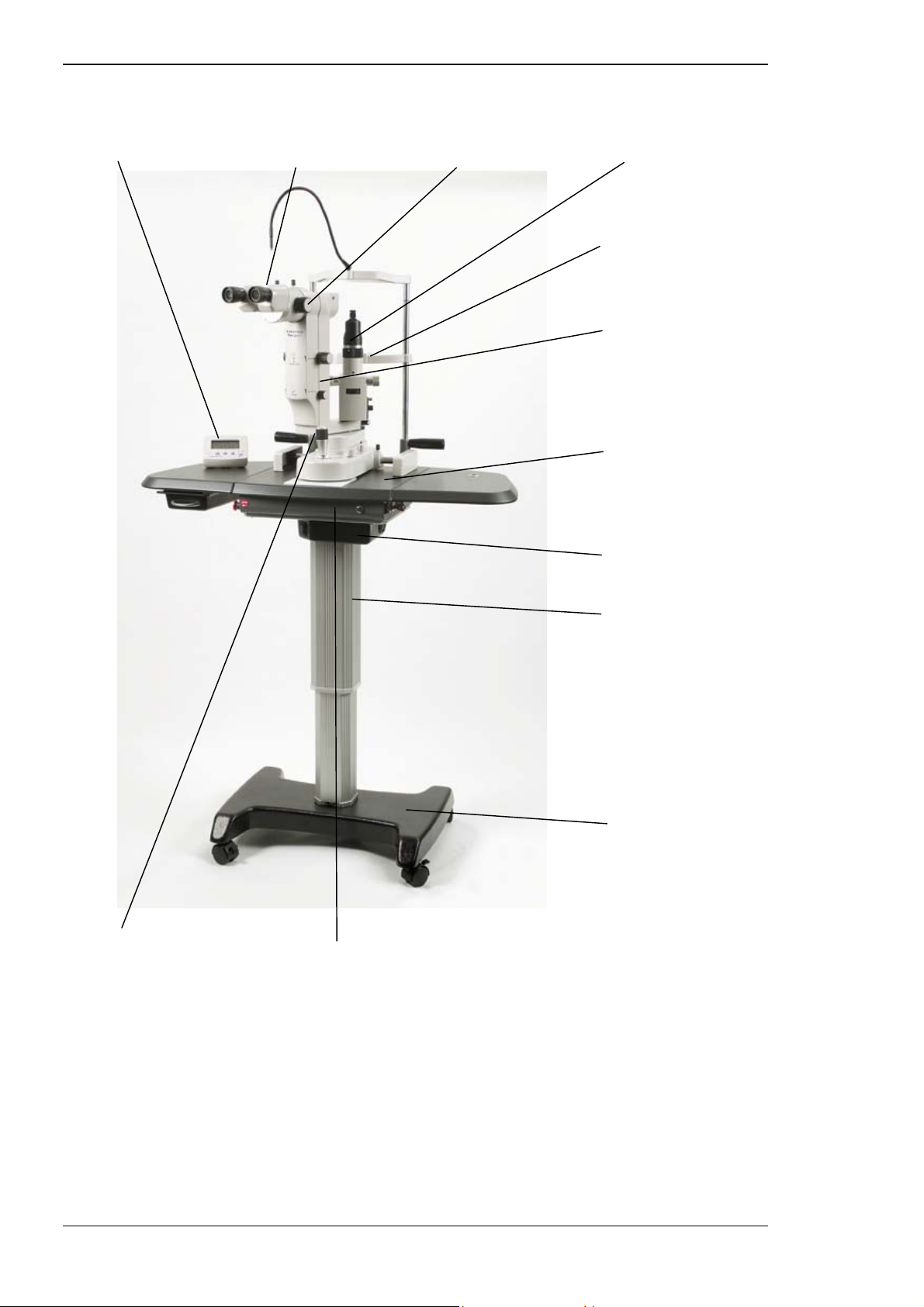
The Tango is illustrated in Figure 1–1.
U.S. Law restricts this device for sale to, or on the order of, a physician.
Tango, Ultra Q and Solo Service Manual 1-1
Issue 2.0
Page 16
Introduction
Figure 1–1 General view of the Laserex Tango
Control module Binocular head Magnification changer Slit lamp
Chinrest
Laser head
Table with
extension wings
Joystick/fire switch Power supply console
Switch box
Stand column
Mobile
stand base
(an Access
wheelchair
accessible base is
also available)
1-2 Tango, Ultra Q and Solo Service Manual
Issue 2.0
Page 17

1.2 COMPONENTS
The major components of the Laserex Tango, Ultra Q and Solo are:
⇒ laser head — containing the laser, optics and modules
⇒ binoculars
⇒ table — incorporating a power supply console, switch box and
extension wings
⇒ joystick with fire switch — used to move the slit lamp and fire the
laser
⇒ control module — mounted on either table extension wing
⇒ stand — motorised to move the table up and down
⇒ Mobile base on castors, or Access wheelchair accessible base
The laser head components are installed inside a cast metal housing.
Introduction
1.3 THEORY OF OPERATION
When the instrument is ready for firing and the fire switch is pressed, the
microprocessor initiates a series of safety checks. If these are successful, it
sends a signal to the treatment laser controller, which supplies electrical
power to the laser. This is then converted to laser energy.
The treatment laser beam is parfocal and coaxial with a diode aiming laser.
A safety filter shields the surgeon’s eye, so only the red aiming spot is seen.
The aiming spot (and hence also the treatment beam) is positioned on the
patient’s retina with the aid of a slit lamp microscope.
The energy of the laser pulses is readily adjustable, and is normally set at
the lowest possible effective level in order to minimise unwanted side
effects. The spot size is typically set to 1-200 micrometres (µm).
Tango, Ultra Q and Solo Service Manual 1-3
Issue 2.0
Page 18

1.4 WHAT IS A LASER?
LASER is an acronym for Light Amplification by Stimulated Emission of
Radiation.
In its most basic form, a laser is a device that converts electrical energy to
light. The conversion efficiency is quite low; of the order of 1–4%, but the
light produced is quite different from other sources such as fluorescent
tubes or the sun. The differences are:
⇒ coherence — all the waves are exactly in phase, with no interference
between waves, so there is no loss of energy
⇒ monochromaticity — the range of wavelengths or energies present is
extremely small
All other sources of light or heat have a broad range of energy (or
wavelengths). Since lasers have a narrow range, a beam can be
selected with a wavelength well matched to the absorption
properties of the tissue of interest, for best effect.
⇒ collimation — the beam does not diverge and can therefore travel a
long way and still have a small spot size
Introduction
1.4.1 Stimulated emission
The laser beam is produced by the process of stimulated emission. During
this process, atoms are excited above their ground state by an energy
source (a flash lamp in the Tango, Ultra Q and Solo). When the excited
atoms return to their ground state they emit photons, which are then
reflected by mirrors back and forth over the laser medium within the laser
cavity.
When a photon hits an already excited atom in the laser medium the atom
emits another photon. In other words, one photon enters and two leave,
both in the same direction as that of the incoming photon, and both with
exactly the same phase in relation to each other (that is, coherent), and at
the same wavelength.
1.4.2 Medical advantages
For medical use the differences between laser light and other sources offer
the following major advantages in their clinical applications:
⇒ significantly higher power densities at the target tissue
⇒ ability to match the wavelength to the absorption properties of the
tissue of interest for a desired effect
⇒ ease of focusing a parallel beam to small spot size
1-4 Tango, Ultra Q and Solo Service Manual
Issue 2.0
Page 19
Introduction
Caution
These same properties also give laser radiation a greater potential to
cause injury than light from other sources.
Like all Nd:YAG ophthalmic laser surgery, there are risks involved, and use
of the YAG or SLT treatment lasers may be contraindicated for patients with
certain pre-existing ocular pathologies. Objective assessment of candidate
patients for each procedure must be done in light of the risks, which are
discussed in detail in the user guide supplied with the instrument.
1.4.3 Elements of a laser
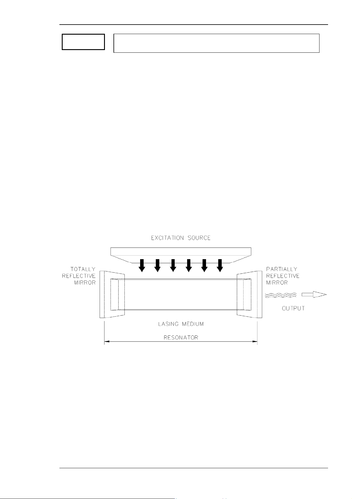
A laser has three major components:
⇒ laser medium — a solid, liquid or gas where the energy from the
source is absorbed and photons are emitted
⇒ energy source or pump — such as a flash lamp
⇒ resonant laser cavity — in which the photons are reflected back and
forth, producing pulses of laser light
Figure 1–2 illustrates the components of a typical laser.
Figure 1–2 Typical laser components
Tango, Ultra Q and Solo Service Manual 1-5
Issue 2.0
Page 20

Introduction
Laser medium
The laser (or lasing) medium used in the Laserex Tango, Ultra Q and Solo is
a solid-state crystal of Neodymium-doped Yttrium Aluminium Garnet
(Nd:YAG).
Energy source or pump
The energy source for both the Tango, Ultra Q and Solo is a flash lamp
containing ionised gas. It receives pulses of electrical energy, which are
conducted by the ionised gas, causing a discharge of high voltage energy.
The energy is released as a bright flash of light. The laser medium absorbs
and re-emits certain wavelengths, forming the laser beam by the process of
stimulated emission (see Section 1.4.1).
Laser cavity
The cavity contains the flash lamp, the laser medium, and a series of totally
and partially reflective mirrors that reflect the photons and allow a polarised
beam of laser light to exit.
Pulsed operation and Q-switching
The Laserex Tango, Ultra Q and Solo use a pulsed mode of operation
commonly called Q-switching. In this system a component called a Qswitch is added to the laser system to cause the laser to produce a short
pulse (on the order of a few nanoseconds (ns)) each time the laser is fired.
The Q-switch can produce a number of laser pulses for a single firing of the
flash lamp. The number of pulses emitted is proportional to the energy
input to the flash lamp, which is provided by a conventional capacitorcharging power supply.
The main discharge capacitor is a 64 microfarad (µF) 900 V pulsed device.
The energy entering the flash lamp is proportional to the square of the
capacitor voltage characteristic, as shown in the illustration below, which
shows flash lamp voltage versus Nd:YAG energy output.
It is important that when the laser is being operated, the voltage to the
flash lamp must be set correctly to prevent the possibility of too few or
too many pulses.
1-6 Tango, Ultra Q and Solo Service Manual
Issue 2.0
Page 21

Introduction
Figure 1–3 Flash lamp voltage vs Nd:YAG energy output
1.4.4 YAG laser theory of operation (Tango/Ultra Q)
The YAG treatment beam operates by photodisruption. The energy of the
pulses produced by the laser is adjustable and the energy density at the
focal point is sufficient to create a small ionisation site (plasma) in the
vitreous cavity. The plasma produces an acoustic wave that radiates from
the focal point and ruptures or disrupts adjacent tissue. This is known as the
'photodisruptive effect’ (see below).
The YAG treatment beam is intended to be used for dissection of the
posterior capsule of the eye (posterior capsulotomy), dissection of the
pupillary membrane of the eye (posterior membranectomy), as well as
other surgical procedures such as iridotomy (opening a hole in the iris).
Unlike other lasers commonly used in ophthalmology (such as argon,
krypton and ruby laser coagulators), it does not rely on thermal effects.
Tango, Ultra Q and Solo Service Manual 1-7
Issue 2.0
Page 22
Introduction
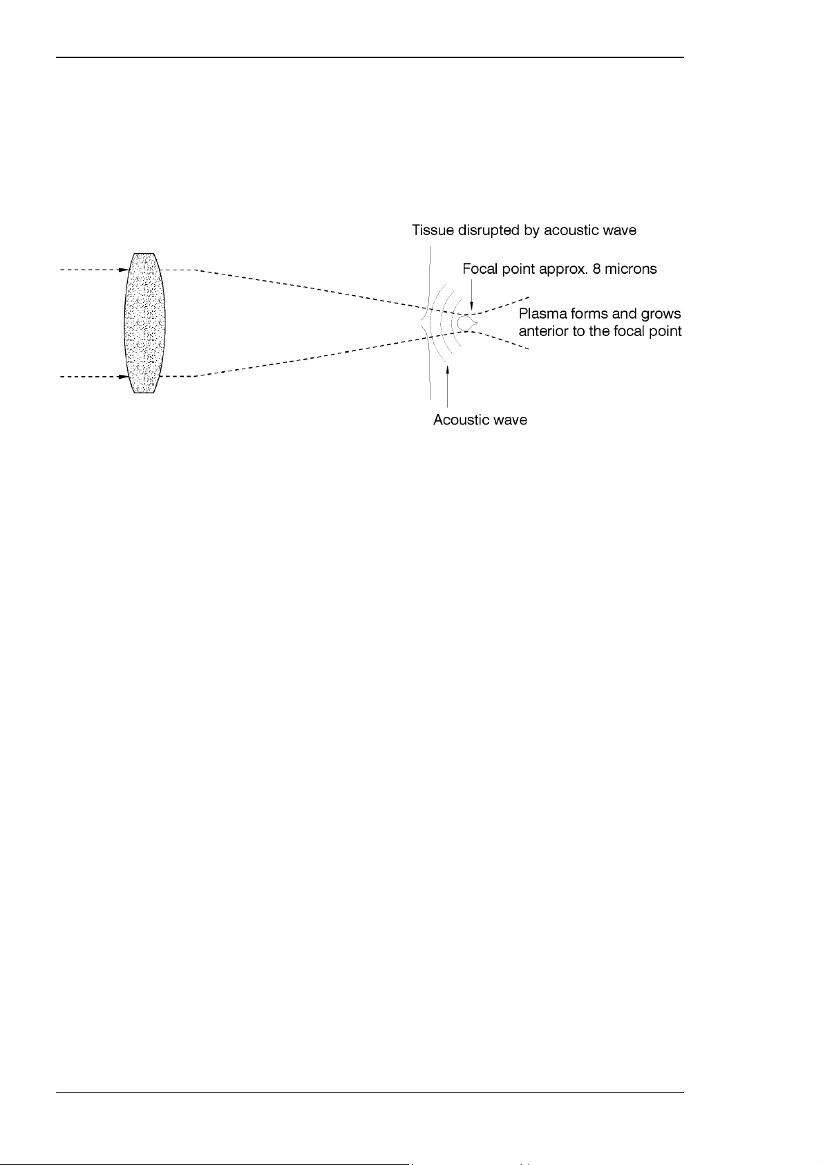
The photodisruptive effect
The eight-micrometre (µm) spot produces a small ionisation site (plasma) at
the focal point. This creates an acoustic wave that disrupts nearby tissue in
a process known as the ‘photodisruptive effect’.
Figure 1–4 Plasma formation
Once formed, the plasma absorbs and scatters further incident light, and
this shields the underlying structures from damage. The beam divergence
after the focal point also protects the retina from damage that could
otherwise occur by the absorption of concentrated YAG treatment energy.
As the treatment energy is increased, the size of the plasma formed also
increases, which causes a larger, stronger acoustic wave. To avoid the
possibility of the plasma damaging the intraocular lens (IOL) by causing
cracking, pitting or chipping, and to allow the accompanying shock wave to
be most effective, the treatment beam may be offset further behind the
membrane to be penetrated (posterior to the focal plane of the slit lamp,
which is focused on the membrane). A posterior YAG offset control allows
selection of the amount of offset required (see below).
The energy of the laser pulse(s) is continuously adjustable, and is normally
set at the lowest possible effective level in order to minimise unwanted side
effects. (These side effects and contraindications for the use of the
instrument are covered in depth in the Laserex Tango and Ultra Q user
guides.)
1-8 Tango, Ultra Q and Solo Service Manual
Issue 2.0
Page 23
Introduction
Posterior Nd:YAG offset
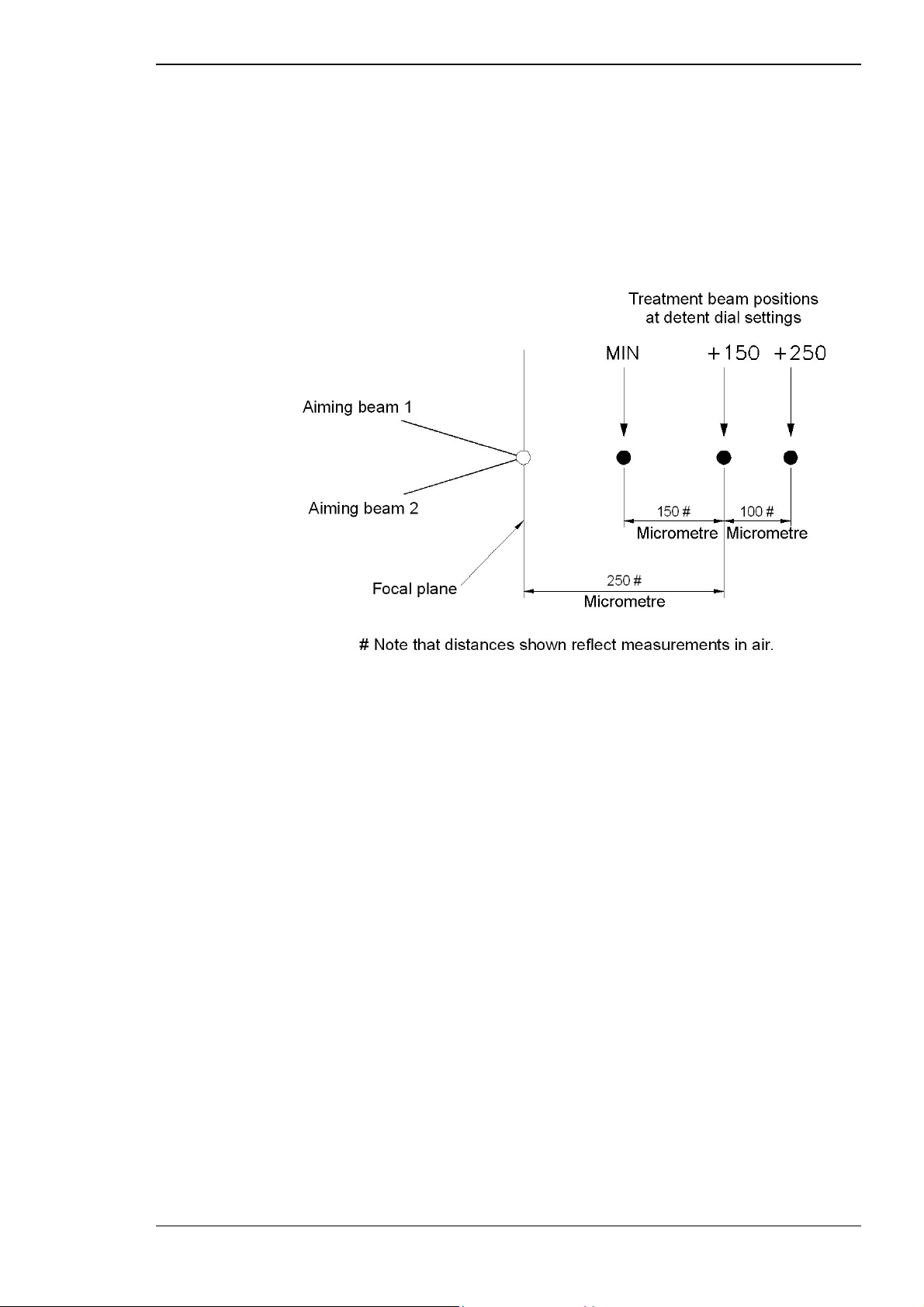
The Laserex Tango and Ultra Q both have an adjustable posterior YAG
offset of 100 to 250 µm between the treatment laser focus and aiming
beams, as illustrated below. This offset is adjusted using the Posterior YAG
Offset control knobs on the front of the laser head. The normal initial setting
is 150 µm.
Figure 1–5 Posterior YAG offset
Aiming beams
A visible red diode dual spot laser is used to aim the treatment laser beam.
The aiming beams are coaxial with the treatment beam and the laser is
focused when the two aiming beams converge to form one spot.
During installation of the laser head on the slit lamp, this low power diode
laser light is set to focus at the same plane as the slit lamp (parfocal with the
slit lamp).
General description of treatments
Treatment procedures are dealt with in detail in the user guide supplied
with the instrument.
In summary, the laser is focused on the membrane or tissue of the patient’s
eye using the aiming beams. The energy is set to the lowest possible
effective level, then the laser is fired. The treatment beam has a cutting or
disrupting effect with the capability to damage any tissue or structure on
which the beam is focused.
If the capsule is tough or scarred, higher energy levels may be required, but
the energy is increased in small increments and the minimum number of
shots required to obtain an adequate opening is used.
Once an opening has been established, it is enlarged as required until it is
of adequate size.
Tango, Ultra Q and Solo Service Manual 1-9
Issue 2.0
Page 24

Introduction
1.4.5 SLT theory of operation (Tango/Solo)
The Tango and Solo include an SLT treatment beam. The Ultra Q has only
the YAG treatment beam but can be upgraded to include an SLT treatment
beam.
The SLT treatment beam in the Tango and Solo operates by reducing
intraocular pressure. The energy of the pulses produced by the laser is
adjustable but much lower than the YAG treatment beam. It does not
produce a photodisruptive effect.
The laser pulses are accurately positioned by means of a coaxial aiming
beam and a gonioscopy contact lens fitted in the patient’s eye to selectively
target a pigmented trabecular meshwork of cells. The 532 nm wavelength is
absorbed more readily by the pigmented cells, causing them to be
destroyed but leaving the trabecular support structure intact.
Aiming beam
A visible red diode single spot laser is used to aim the treatment laser beam.
The aiming beam is coaxial with the treatment beam and has a fixed focus.
During installation of the laser head on the slit lamp, this low-power diode
laser light is set to focus at the same plane as the slit lamp (parfocal with the
slit lamp).
General description of treatments
Treatment procedures are dealt with in detail in the user guide supplied
with the instrument.
In summary, the laser is aimed at the trabecular network to be treated using
the aiming beam and a gonioscopy contact lens. The energy is set to the
lowest possible effective level, then the laser is fired.
The energy may only be increased in small increments and the minimum
number of shots should be used to obtain adequate destruction of the
pigmented cells.
1-10 Tango, Ultra Q and Solo Service Manual
Issue 2.0
Page 25
2.1 SAFETY CLASSIFICATION AND WARNINGS
The Tango, Ultra Q and Solo are all classified as Class IIIb/3B laser
products and Class I Type B electrical protection products. They have been
manufactured to be in compliance with the following standards:
⇒
IEC 60601-1; 1988, Electrical Safety Standard for Medical
Equipment
C HAPTER 2
SAFETY
Caution
Caution
⇒
IEC 60601-2-22; 1995, Requirements for Safety of
Diagnostic/Therapeutic Equipment
⇒
IEC 60825-1; 1993, Safety of Laser Products, part 1
⇒
USA Code of Federal Regulation 21CFR 800 - 1299
⇒
EN 601-1-2:2001, Electromagnetic compatibility
The following laser safety warnings apply to users.
Eye protection
Visible or invisible laser radiation is emitted from the delivery system
when it is in laser READY status and the fire button is pressed.
Do not look into the YAG or SLT treatment beam.
The operator is protected from hazard while in the normal operating
position because the instrument is fitted with protective filters.
Check the safety filters regularly for any imperfections in the coated
surface. Deterioration of the coating causes the SLT treatment beam to
appear as green light.
If any imperfections are present, do not use the instrument. Refer to
Section 8.5.
Appropriate safety glasses should be available outside the room for all
people requiring access. Any viewing ports or windows to the room must
be covered.
Tango, Ultra Q and Solo Service Manual 2-1
Issue 2.0
Page 26

Safety
Safety interlocks and warning lamps may be fitted to the room.
Avoid using reflective instruments. It is also recommended that all surfaces
in the room be matt finish to prevent possible reflection of the laser.
YAG laser emission warning (1064 nm)
Caution
Caution
Class 3B/IIIb Laser Product: avoid direct exposure to beam.
Viewing through all slit lamp optical accessories including camera adaptors
and co-observation tubes is safe for the viewing eye because the built-in
filter provides protection. Protection at an OD of at least 5 @ 1064 nm
must be provided for the eye that is not directly viewing through the
accessory.
All other persons attending the procedure (except the patient being treated)
must wear safety glasses, goggles or masks designed to prevent
transmission of 1064 nm wavelength laser light (optical density (OD) 5 @
1064 nm).
Safety glasses or safety filters providing protection from other wavelengths
may not offer any protection from 1064 nm wavelength and should not be
used.
SLT treatment beam emission warning (532 nm)
Class 3B/IIIb Laser Product: avoid direct exposure to beam.
The operator is protected from hazard while in the normal operating
position because the instrument is fitted with protective infrared absorption
filters. All other persons attending the procedure (except the patient being
treated) must wear safety glasses, goggles, or masks designed to prevent
transmission of 532 nm wavelength laser light (optical density (OD) 5 @
532 nm).
Viewing through all slit lamp optical accessories including camera adaptors
and co-observation tubes is safe for the viewing eye because the built-in
filter provides protection. Protection at an OD of at least 5 @ 532 nm must
be provided for the eye that is not directly viewing through the accessory.
Safety glasses or safety filters providing protection from other wavelengths
may not offer any protection from 532 nm wavelength and should not be
used.
2-2 Tango, Ultra Q and Solo Service Manual
Issue 2.0
Page 27
Safety
Aiming laser emission warning (635 nm)
Caution
The aiming laser used in the Tango, Ultra Q and Solo is a 635 nm Class
II/2 Laser.
Visible laser radiation is emitted from the delivery system when it is
switched on and is in the STANDBY or READY status. Do not stare into
the aiming beam unless under the control of a qualified ophthalmic
surgeon.
Use the lowest practical aiming beam intensity and minimum required
exposure time.
The aiming beams are red diode lasers with a wavelength of 635 nm. It is a
Class II/2 laser with power less than 0.95 milliwatts (mW).
“Class II/2 lasers are not intrinsically safe but eye protection is normally
afforded by aversion responses including the blink reflex”.
(Quoted from IEC 60825-1: 1993.)
Damage to the retina from the aiming beam is most improbable, but it is
still advisable to avoid staring into the beam unless under controlled
conditions.
Regularly check the aiming beam spot shape to ensure good optical
alignment and no fibre damage.
Caution
Caution
Do not fire the treatment laser if the aiming beam is not present.
Reflection warning
Objects that reflect visible light will reflect 1064 or 532 nm laser light.
Avoid placing reflective materials such as glass, metal and polished plastic
in the laser beam path.
Explosion hazard warning
The use of flammable anaesthetics or oxidising gases such as nitrous
oxide (N2O) and oxygen should be avoided. Some materials, for example
cotton wool when saturated with oxygen may be ignited by the high
temperatures produced in NORMAL USE of the LASER EQUIPMENT. The
solvents of adhesives and flammable solutions used for cleaning and
disinfecting should be allowed to evaporate before the LASER
EQUIPMENT is used. Attention should also be drawn to the danger of
ignition of endogenous gases.
Electromagnetic compatibility
Caution
Tango, Ultra Q and Solo Service Manual 2-3
Issue 2.0
This device may be affected by portable and mobile RF communications
equipment (such as mobile phones) in the vicinity during operation.
Page 28

Laser mode — Tango only
Safety
Caution
The Tango can be operated in either YAG or SLT modes. Always check the
correct mode is selected before use.
Eye damage may result from use of the incorrect treatment mode.
Safety signs
Safety signs should be displayed warning of Class IIIb/3B Laser and Class
IIb/2B in operation.
2.2 SAFETY FEATURES
The Tango, Ultra Q and Solo include a number of safety features provided
in accordance with the requirements of the appropriate standards. They
also include a number of additional safety features, which are listed later in
this section.
Features relating to standards
The Tango, Ultra Q and Solo are designed and built to comply with the
following standards:
Electrical and laser product standards
⇒
IEC 60601-1; 1988 — Electrical Safety Standard for Medical
Equipment (encompasses AS3200.1; 1990)
⇒
IEC 60601-2-22; 1995 — Requirements for Safety of
Diagnostic/Therapeutic Equipment
⇒
IEC 60825-1; 2001 — Safety of Laser Products, part 1.
⇒
21CFR 1040.10, 1040.11 — USA Code of Federal Regulation
⇒
Australian Standard AS/NZS2500:1995 — Guide to the Safe Use of
Electricity in Patient Care
⇒
Australian Standard AS/NZS2211:1997 — Laser Safety
Manufacturing standards
⇒
93/42/EEC for CE Marking
⇒
ISO 13485:1996 — Quality Management System
⇒
United States Code Of Federal Regulations Title 21 part 820 — a
Quality System Regulation
The safety features provided in accordance with these standards include
those described in the following table.
2-4 Tango, Ultra Q and Solo Service Manual
Issue 2.0
Page 29

Safety
Table 2–1 Safety features
Feature Description
Lockable key switch The system can only be turned on with the correct key. The key
cannot be removed while in the ON position, so the laser cannot
operate without the key in place.
Emergency Laser
Stop switch
Laser ON/OFF pushbutton switch
Laser Selection
Button (inactive in
the Ultra Q and
Solo)
The system may be used only when this switch is in the normal ON
position (out). If pressed to the OFF position (in) all power to the
system is immediately cut to eliminate any risk of laser irradiation.
The switch is a large, red, mushroom shaped push-button for ease of
visibility and access. When pressed in, the button can only be
released by turning it clockwise to the ON position. This restarts the
system and returns it to STANDBY status.
The Laser ON/OFF switch activates the aiming beams and the
selected treatment laser provided the key switch is ON, the
Emergency Laser Stop switch is ON, and the interlock is closed
(where applicable).
In the OFF position the switch is not illuminated, the slit lamp is ON
but the treatment lasers and aiming beams are off.
When pressed in to the ON position the switch is illuminated
(orange) and a laser test fire occurs. The aiming beams and slit lamp
are on, and the treatment laser may be activated by placing the
system into READY status and selecting the required laser.
This button selects YAG or SLT mode. It is only active if the Laser
ON/OFF switch is in the ON position.
The selected mode is displayed on the control module screen.
Laser READY/
STANDBY indicators
These LEDs on the control module indicate whether the instrument is
in READY (red) or STANDBY (yellow) status.
After the Laser ON/OFF switch is pressed ON, diagnostic tests are
carried out, after which the STANDBY indicator is lit, and the last
used treatment mode is indicated.
The status is toggled by pressing the Ready/Standby button on the
control module. READY status must be manually selected before the
selected laser is made available for firing.
Safety remote
interlock
This is a user-installed feature and is highly recommended.
A connector is provided on the side of the console for connection to
a theatre door interlock switch. The switch turns off the aiming
beams, disables the controls and prevents the laser from firing when
the door is opened. These functions are returned two seconds after
the door is closed or interlock is satisfied. The unit is supplied fitted
with a bypass plug, which is easily removed if the interlock is to be
fitted.
Safety shutter Each laser and optical system module is equipped with a spring
loaded safety shutter that keeps the treatment laser optical path
blocked unless the system is manually switched in READY status, the
treatment laser is selected and the laser fire switch is pressed.
Tango, Ultra Q and Solo Service Manual 2-5
Issue 2.0
Page 30

Safety
Feature Description
Tower interlock
(inactive in the
Ultra Q and Solo)
The rotation of the slit lamp tower is monitored via an interlock. If the
slit lamp is in line with the objective lens and the unit is in YAG mode,
it beeps, a warning message appears on the display, and the diode
aiming beams flash until the tower is rotated away from the beam
path. No laser emission is allowed until this condition is rectified.
Excess energy
detection
Energy deviation
warning
The system shuts down if more than double the set energy is
delivered.
The system warns the operator if delivered energy deviates more than
±20% from the set value.
Protective housings Protective housings on the laser and optical system, as well as the
control and display systems, prevent the operator from being
inadvertently exposed to laser emission or high voltage shock. The
protective housings cannot be removed without tools and must only
be opened by authorised service personnel.
Location of controls All the operator controls are located so that there is no risk to the
operator of inadvertent laser exposure.
Ocular filters The operator viewing port on the laser and optical system module
contains a safety filter to limit the exposure level to the operator's
eyes to below class 1 limits. Any standard slit lamp viewing accessory
can be used with the Tango, Ultra Q or Solo slit lamp without
hazard.
FDA and IEC
compliance labels
Electrical leakage
protection
Locations and illustrations of the safety compliance labels are
contained in the safety labels section.
A medical grade power supply is built into the power supply console.
This ensures that the complete instrument including the slit lamp
power supply meets the requirements of IEC 601-1 for earth leakage
protection, earth resistance and dielectric strength.
Additional safety features
The Tango, Ultra Q and Solo are equipped with safety features in addition
to the mandatory requirements specified by IEC and FDA:
Table 2–2 Additional safety features
Feature Description
Memory test When the Tango, Ultra Q or Solo is first switched on the system
automatically checks the microprocessor memory. If a malfunction is
detected an error code is displayed and the laser cannot be switched
into READY status. See Section 10.2 for a discussion of the error
codes and Chapter 11 for a complete list.
2-6 Tango, Ultra Q and Solo Service Manual
Issue 2.0
Page 31

Safety
Feature Description
Laser power-up test After the memory test the system automatically performs a self-test
program where it confirms the safe and correct operation of the
modules. During this procedure the microprocessor fires a series of
test shots with the shutter closed. If this test routine is satisfied, the
normal operating screen is displayed in the LCD screen on the
control module and the energy of the last test shot is displayed. If a
malfunction is detected, an error code is displayed and the laser
cannot be made to fire. See Section 10.2 and Chapter 11 for a
complete list.
Treatment mode
(Tango only)
At the end of the self-test routine and initialisation process the control
module automatically enters the last used treatment mode (YAG/SLT).
STANDBY status At the end of the self-test routine and initialisation process the control
module automatically enters STANDBY status. In this state the aiming
laser is activated and all the controls function, allowing the treatment
mode and settings to be selected. The treatment laser is disabled and
the laser fire switch will not function.
STANDBY status eliminates the risk of accidental treatment beam
activation during patient set up. To enable the treatment laser to
function, select laser READY status.
Shutter monitor A dual sensor shutter monitor checks the correct opening and closing
of the shutter. In the event of a shutter malfunction, the laser fire
switch is disabled and an error code is displayed in the control
module LCD. See Section 10.2 and Chapter 11 for a complete list.
Automatic test fire Every time an energy setting is changed, either by the Energy Control
or via the selection for the number of pulses, and every time the
treatment mode is changed, an automatic test fire occurs. During this
test fire, the shutter remains closed so there is no risk of exposing the
patient or operator to laser radiation.
After a test fire, the resultant energy is shown on the control module
LCD.
Reset after power
failure
When power is restored after a power failure, the system will restart
and will be in STANDBY status.
Fault conditions If the system detects a fault during operation, an error code is
displayed on the control module LCD. Warnings may be cleared by
the operator, but errors result in automatic system shut down. See
Section 10.2 and Chapter 11 for a complete list.
Tango, Ultra Q and Solo Service Manual 2-7
Issue 2.0
Page 32

2.3 SAFETY PRECAUTIONS
The Tango, Ultra Q and Solo are safe instruments when correctly installed
and operated, and when the safety precautions described in this manual are
followed.
Precautions before first use
Before using the instrument for the first time, read the safety requirements
outlined in this chapter, then become familiar with the controls described
in Chapter 2.
Before using the Tango, Ultra Q or Solo for the first time, ensure that the
equipment is correctly installed and adjusted, and that all safety devices are
operational.
The Tango, Ultra Q and Solo can be operated from 100–120 V or 220–
240 V mains power, with the voltage selected by a voltage selector switch
located at the top of the stand column. Ensure this switch is in the correct
position for the local mains voltage before using the unit for the first time.
Safety
General precautions during use
The following general precautions apply:
⇒
never operate the laser unless it is correctly positioned on a level,
stable surface
⇒
protect the Tango, Ultra Q and Solo from unqualified use by always
removing the key from the power supply console when the laser is
not in use
⇒
DO NOT FIRE THE TREATMENT LASER IF THE AIMING BEAM IS
NOT PRESENT
⇒
check the ground resistance and earth leakage currents according
to IEC 60601-1 at least once every 12 months
Using a gonioscopy lens
When carrying out a selective laser trabeculoplasty procedure with the Solo
or the Tango in SLT mode a special gonioscopy contact lens is used to
deflect the laser towards the trabecular meshwork in front of the iris. The
lens is available from Laserex.
Refer to the information supplied with the lens for complete instructions.
2-8 Tango, Ultra Q and Solo Service Manual
Issue 2.0
Page 33

Safety
Physical safety precautions
Do not use or service this instrument unless you understand the potential
hazards inherent in laser technology.
Never place your hands, arms, or any other body parts or tissue in the path
of the treatment laser beam.
When the instrument is unattended, turn it off and remove the key. Store
the key in a safe place.
2.4 ELECTRICAL SAFETY PRECAUTIONS
Caution
Caution
Caution
Danger! High voltage.
Switch off the instrument and disconnect it from mains power before
servicing. Re-connect to power only if it is necessary for the particular
servicing procedure involved.
Do not attempt to service the instrument if you are not familiar with
precautions against electrical shock.
Ensure all safety precautions against electrical shock are followed as the
laser system is powered from a 100 – 120 V AC or 220 – 240 V AC supply.
Voltages of up to 12 kV are generated internally.
This system contains high voltage capacitors. Check that the capacitors
have been discharged by the automatic dump circuit or bleed resistors
before servicing.
Tango, Ultra Q and Solo Service Manual 2-9
Issue 2.0
Page 34

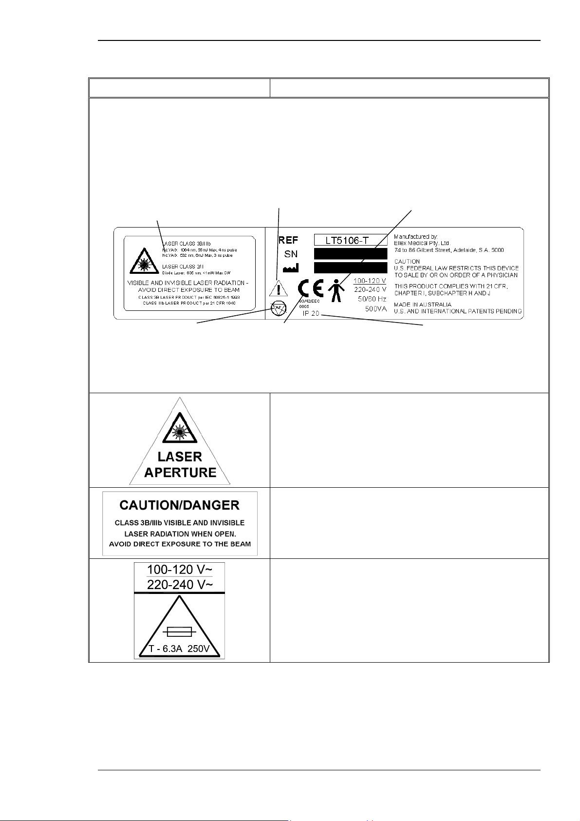
2.5 SAFETY LABELS
In compliance with MDD 93/42/EEC, FDA guidelines and International
Standard IEC 60601.1, this section contains a facsimile of every safety label
and voltage/power rating label attached to the Tango, Ultra Q and Solo.
Figure 2–1 Safety label locations
Safety
a
100-120 V~
220-240 V~
T - 6.3A 250V
2-10 Tango, Ultra Q and Solo Service Manual
Issue 2.0
Page 35
Safety
Table 2–3 Description of safety labels
Label Description
Compliance label
Warning label indicating
laser radiation hazard and
class of treatment and
aiming beam lasers.
Warning label indicating the
possible explosion hazard if
equipment is used in the
presence of flammable
anaesthetics.
Symbol indicating the user
must read and understand
the user guide before
using the system.
CE symbol indicating compliance
with the Medical Device
Directive (MDD) 93/42/EEC for
CE marking.
Compliance label showing type B
equipment symbol. This symbol
indicates that the equipment provides
protection against electric shock
through the limiting of leakage current
and the provision of a protective earth
connection. Complies with IEC
60601-1.
Symbol indicating level of
ingress protection.
Laser aperture.
Warning and explanatory label showing the position
of the laser aperture. Complies with IEC 60825-1
and 21 CFR 1040.11(a) (3).
Protective cover label.
Warning label explaining laser class and hazards of
direct exposure.
Voltage.
Label indicating the mains supply voltage and the
type and rating of user-accessible fuses.
Tango, Ultra Q and Solo Service Manual 2-11
Issue 2.0
Page 36
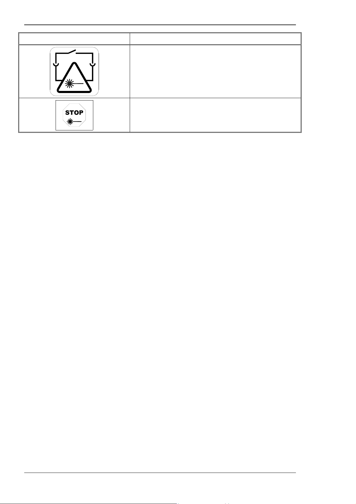
Safety
Label Description
Safety remote (theatre door) interlock.
Emergency Laser Stop switch.
2.6 CALCULATING NOMINAL OCULAR HAZARD DISTANCE
The nominal ocular hazard distance (NOHD) for the Laserex Tango and
Ultra Q is 6.1 metres for the YAG treatment beam.
In the Tango and Solo, the NOHD is approximately 69 metres for the SLT
treatment beam.
The nominal ocular hazard distance is calculated from the output energy,
beam divergence and diameter, and the maximum permissible exposure
energy. The calculation is made using formulae from the American Standard
ANSI Z1361-1986 (page 66), the equivalent Australian Standard
AS/NZS2211.1:1997 (page 74), and EN60825-1:1993 (page 143).
2-12 Tango, Ultra Q and Solo Service Manual
Issue 2.0
Page 37
The Tango, Ultra Q and Solo systems are designed for use only by
ophthalmologists within consulting rooms and in operating theatre
environments.
3.1 LASER AND OPTICAL SYSTEMS
The Tango, Ultra Q and Solo are compact, easily moved and self-contained
units designed with operational safety and reliability as the primary design
criteria. They include three major sub-assemblies:
C HAPTER 3
FUNCTIONAL DESCRIPTION
⇒
laser head, comprising:
→ slit lamp (see Sections 3.2.1 and 3.5.4)
→ integrated YAG treatment laser beam and aiming beam system
for photodisruption operations (see Section 3.2.4) — Tango and
Ultra Q
→ integrated SLT treatment laser beam and aiming beam system
for selective laser trabeculoplasty (see Section 3.2.5) — Tango
and Solo
→ sensors, shutters, filters and lenses to control and focus the
beams (see Sections 3.2.4 and 3.2.5)
⇒
power supply console (mounted under the table), comprising:
→ YAG power supply module (see Section 3.3.1)
→ DC switch mode power supply module (see Section 3.3.2)
⇒
table, comprising:
→ motor-driven adjustable stand (see Section 3.4)
→ control module mounted on the tabletop to operate the
instrument (see Section 3.5.1)
→ microprocessor (in the control module) to control the system
(see Section 3.5.1)
⇒
Electrical system (see Chapter 4)
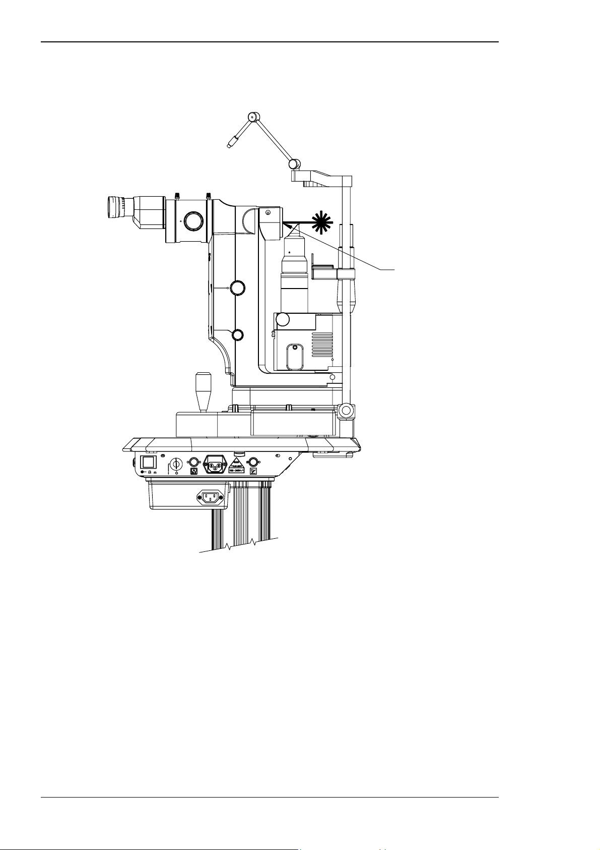
See Figure 1–1 for a general view of the system and Figure 3–1 for the
location of the laser aperture. The controls, features and adjustments are
described in Section 3.5.
Tango, Ultra Q and Solo Service Manual 3-1
Issue 2.0
Page 38
Functional description
Figure 3–1 Location of laser aperture
Laser aperture
3.2 LASER HEAD COMPONENTS
The laser system consists of a number of discrete optical modules, which
are all mounted on a common set of precision machined and positioned
rails, ensuring accurate and repeatable positioning of the modules relative
to the system bore sight.
The lasers and their delivery systems are integrated into a slit lamp
microscope, which is mounted on the power lift table.
The illumination system comprises a 30 W halogen lamp. The light from this
lamp is delivered to the viewing plane through various lenses and prisms.
Refer to Section 3.5 for a description of controls and adjustments for these
components.
3-2 Tango, Ultra Q and Solo Service Manual
Issue 2.0
Page 39
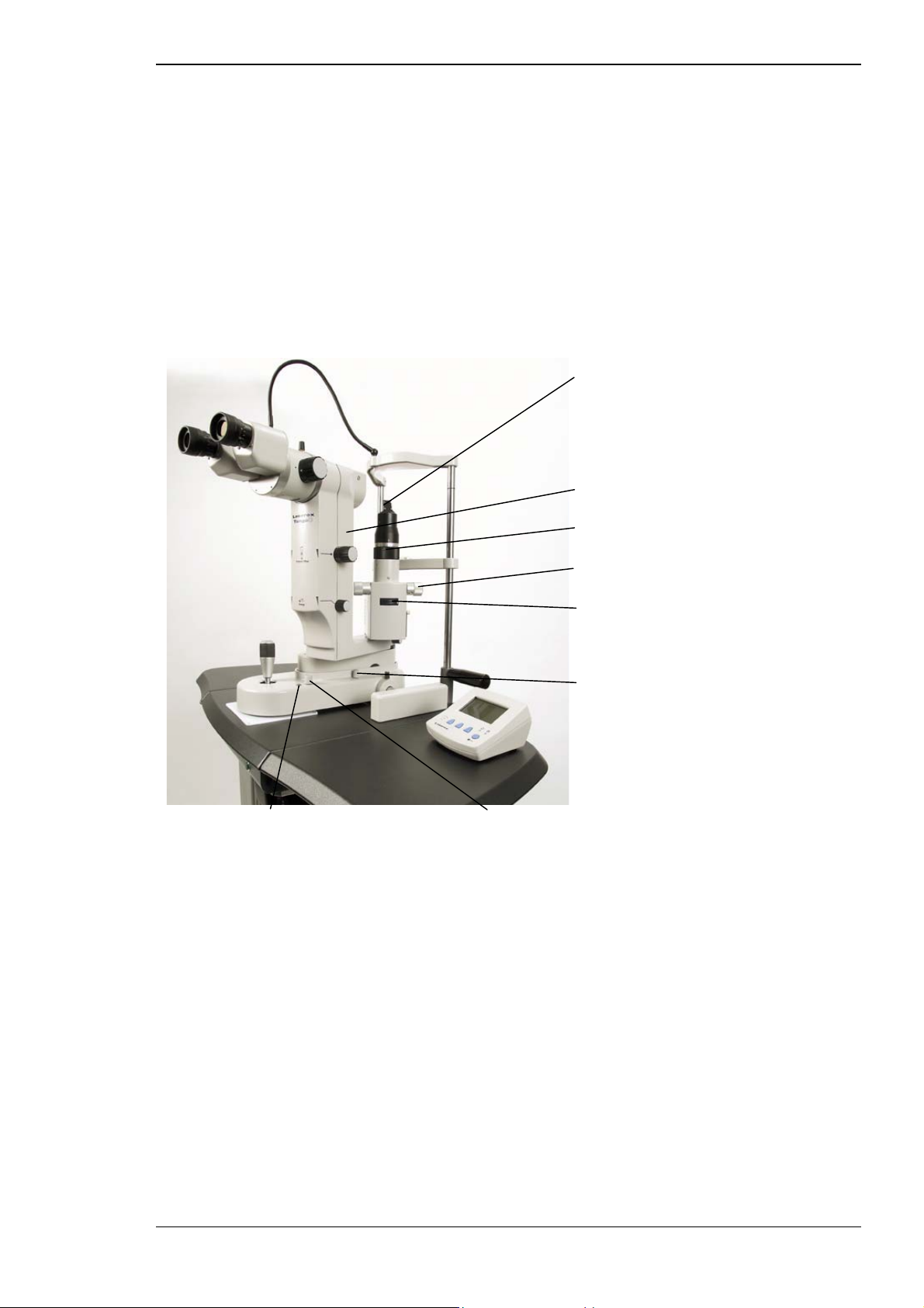
3.2.1 Slit lamp
The slit lamp in the Tango, Ultra Q and Solo has been modified from the
standard slimline binocular head support arm and magnification changer, to
a special enlarged support arm containing all the laser optics. All slit lamp
features and controls remain unchanged.
The Tango, Ultra Q and Solo are supplied with fixed magnification of 16 x
using 12.5 x eyepieces. A three-step magnification changer is fitted between
the binocular head and the support arm.
Figure 3–2 Slit lamp
Functional description
Illumination beam splitter
Laser head
Slit rotation
Slit width control
Filters and apertures
Aiming beam intensity
Illumination boost (push-button) Illumination intensity
Viewing path
The viewing path for the treatment lasers consists of a binocular assembly
(delivered with 12.5 x eyepieces), safety filter, folding mirror and objective
lens. The magnification of this standard system is 16 times.
Optical filters in the view path between the binoculars and folding mirror
module limit the infrared exposure to the operator’s eyes to a level below
the Class 1 safety limit.
When the treatment laser is turned off the Tango, Ultra Q and Solo can be
used as a normal diagnostic slit lamp (see Chapter 7).
Tango, Ultra Q and Solo Service Manual 3-3
Issue 2.0
Page 40

Functional description
3.2.2 Optical modules
The optical modules are as follows:
YAG laser modules — Tango/Ultra Q
⇒
attenuator module — comprising shutters, energy meter, pulse
detector and optic beam splitter, diffuser and filter
⇒
beam expanding telescope (BET) module — comprising positive and
negative lenses and an optic wedge
⇒
Q-switched YAG laser cavity module (common with SLT module in
Tango)
⇒
YAG diode aiming module (DAM)
⇒
YAG folding mirror module (YFMM)
SLT treatment beam modules — Tango/Solo
⇒
frequency doubling module — comprising optic lens and mirror and
a KTP (Potassium Titanyl Phosphate) frequency doubling crystal
⇒
SLT attenuator module — comprising shutters, energy meter, and
optic beam splitter, diffuser and filter and beam splitter
⇒
Q-switched YAG laser cavity module
⇒
SLT diode aiming module (DAM)
⇒
SLT folding mirror module (SLT FMM)
Note that the SLT beam passes through both the SLT folding mirror module
and the YAG folding mirror module and objective lens.
The relationship between these components is illustrated in Figure 3–3 and
3–4. The functions of these modules and components are described in the
remainder of this chapter. Procedures for testing and replacing them, along
with further details about them are included in Chapter 12.
3-4 Tango, Ultra Q and Solo Service Manual
Issue 2.0
Page 41
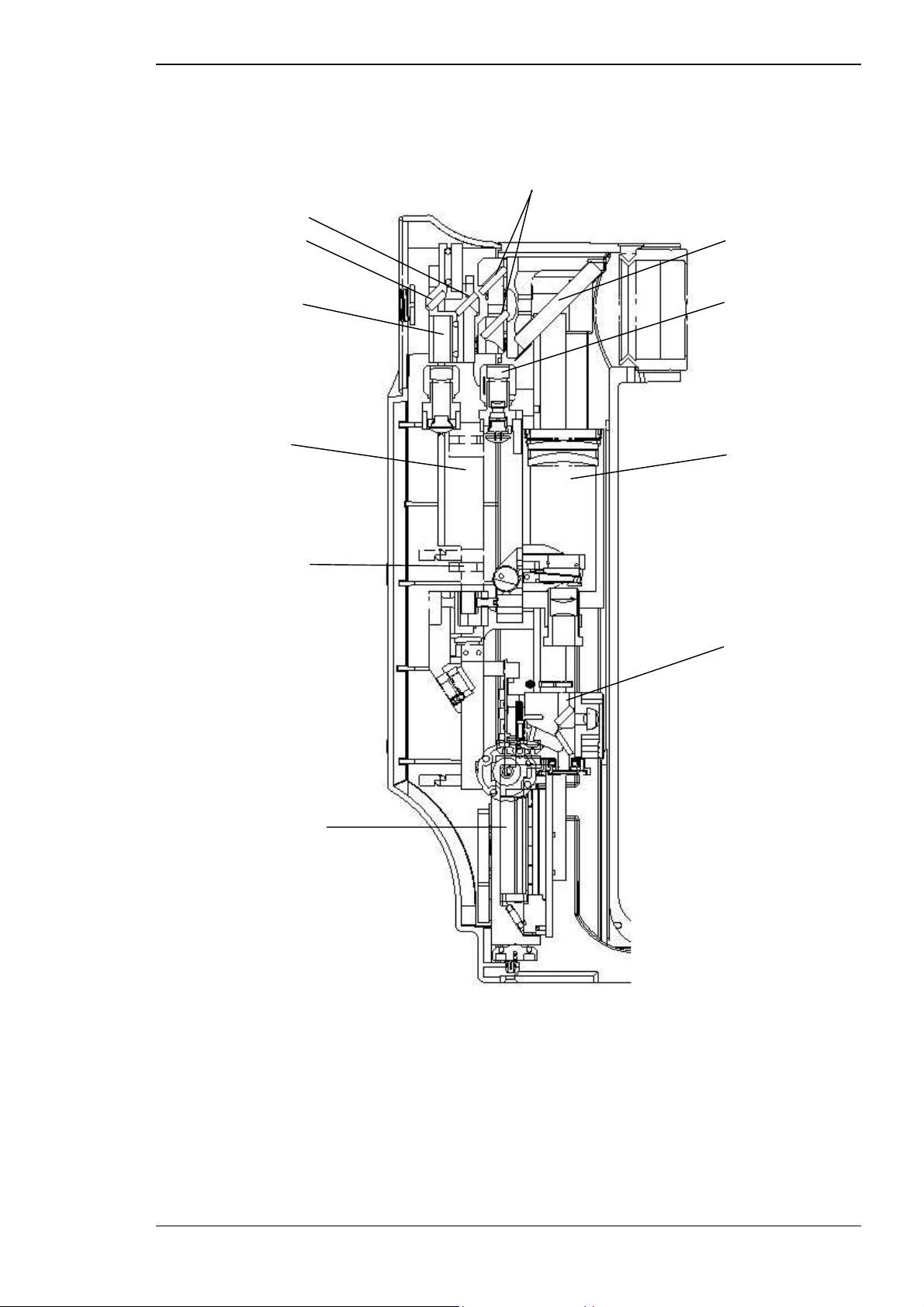
Functional description
Figure 3–3 Position of YAG and SLT laser components (Tango)
YAG aiming mirrors
SLT folding mirror
SLT aiming mirror
SLT aiming laser
SLT attenuator
Frequency doubler
YAG folding mirror
YAG aiming laser
Beam expanding
telescope (BET)
YAG attenuator
Nd:YAG laser cavity
Tango, Ultra Q and Solo Service Manual 3-5
Issue 2.0
Page 42

Functional description
Figure 3–4 Optical block diagram (Tango)
The Ultra Q contains only the photodisruptor modules. Solo contains
only the SLT modules
3-6 Tango, Ultra Q and Solo Service Manual
Issue 2.0
Page 43

Functional description
3.2.3 Modules common to YAG and SLT treatment beams
Q-switched YAG laser module
The Nd:YAG laser cavity produces pulses of laser light. The module consists
of a flash lamp, YAG laser rod, Q-switch and end mirrors.
In operation, the laser rod is excited by the flash lamp and produces laser
emissions in response. The flash lamp voltage is controlled to allow
selection of a single pulse, double or triple laser pulses out of the cavity
from a single flash lamp discharge. (See Chapter 1 for a discussion of the
theory of operation of lasers.)
Trigger module
The trigger module transfers the voltage from the YAG power supply to the
YAG laser flash lamp.
A trigger signal applied to the trigger module produces a high voltage pulse
of the duration required to trigger the flash lamp.
3.2.4 YAG treatment beam
The YAG (Yttrium Aluminium Garnet) treatment beam provides the
physician with a precise, safe means for performing posterior capsulotomy,
pupillary membranectomy, and iridotomy.
The YAG treatment beam is derived from a solid-state laser module that
produces short (approximately 4 ns), individual pulses of focused infrared
light with a wavelength of 1064 nanometres (nm).
When the instrument is ready for firing and the fire switch is pressed, the
microprocessor initiates a series of safety checks. If these safety checks are
successful, it then opens the safety shutter and sends a signal to the high
voltage power supply. This supplies DC voltage to the flash lamp of the
laser, which emits a pulse(s) of laser energy.
The output of the laser module is passed through several optical modules to
allow the beam leaving the objective lens of the slit lamp microscope to be
focused to a high-energy spot with a diameter of 8 µm.
Tango, Ultra Q and Solo Service Manual 3-7
Issue 2.0
Page 44

Functional description
YAG laser characteristics
The YAG treatment laser has the following characteristics:
⇒ wavelength 1064 nm
⇒ high quality pulse of energy up to approximately 15 mJ per pulse
(55 mJ for triple pulse)
⇒ 3 mm beam diameter
⇒ well polarised (ratio: 100:1)
⇒ 4 ns pulse width, directed along the optical axis of the system
⇒ spot size 11 µm (calculated 84% energy in this diameter; full width
half maximum (FWHM)) spot size 8 µm
⇒ focal length 92 mm, working distance 55 mm, and a cone angle of
16 degrees
⇒ dual spot red diode laser aiming system
⇒ adjustable posterior offset up to 250 µm between the Nd:YAG and
the diode focus (refer to Section 13.1 for actual offsets at each
setting on the dial)
YAG laser beam paths
The laser and optics follow three distinct paths:
⇒ treatment beam path — the path of the Nd:YAG laser beam used for
treating the patient
⇒ aiming beam path — the path of the red diode laser beam used for
aiming the laser beam
⇒ viewing path — the path from the eye of the patient to the eye of the
operator (see Section 3.2.1)
These paths are illustrated in Figure 3–4 and below.
3-8 Tango, Ultra Q and Solo Service Manual
Issue 2.0
Page 45
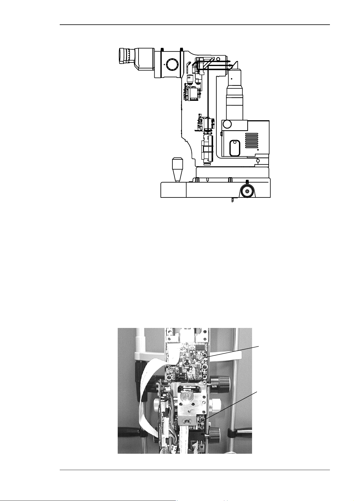
Functional description
Figure 3–5 YAG treatment beam path
Attenuator module
The YAG attenuator module comprises:
⇒
shutters
⇒
energy meter
⇒
pulse detector
⇒
optic beam splitter
⇒
diffuser
⇒
filter
Figure 3–6 YAG and SLT attenuators
SLT attenuator
YAG attenuator
Tango, Ultra Q and Solo Service Manual 3-9
Issue 2.0
Page 46

Functional description
This module contains polarisation-sensitive optics and controls the amount
of energy delivered to the treatment site by optically attenuating the YAG
laser energy output.
After attenuation, a portion of the beam is split by a beam splitter and
directed to a pulse detector that detects the number of pulses out of the
laser. A portion of the beam is also directed into an energy meter to read
the energy level of the attenuated laser beam.
The operator selects the energy level using the ENERGY control knobs on
the laser head. When a test fire is delivered the energy is measured and
displayed on the control module LCD. After the set number of pulses (one,
two or three) is fired the shutter closes. The laser can be fired again after a
minimum time of one second.
The beam then enters a shutter absorber. When the shutter is closed, a total
beam block absorbs the incident energy, but when it is open the beam
passes through to a beam expanding telescope (BET). The shutter is only
allowed to open when READY status is selected.
The internal shutter contains a flash filter to remove visible light from the
beam and prevent it from disturbing the patient when the laser is fired. The
flash filter transmits the Nd:YAG wavelength with minimal loss.
The opened shutter allows the pulse(s) of laser energy to enter a beam
expander, which expands the 3 mm diameter laser beam to 27 mm
diameter. The expanded beam is then reflected 90 degrees to enter the
objective lens, which focuses the beam to a high-energy spot of
approximately 8 µm in diameter (full width half maximum (FWHM).
Beam expanding telescope (BET) module
The YAG beam expanding telescope enlarges the beam diameter from 3 to
27 mm, which allows the beam to be focused to a small spot by the
objective lens.
Figure 3–7 Beam expanding telescope (BET) module
Folding mirror module
Diode aiming module
Beam expanding telescope
Posterior YAG offset
control
3-10 Tango, Ultra Q and Solo Service Manual
Issue 2.0
Page 47
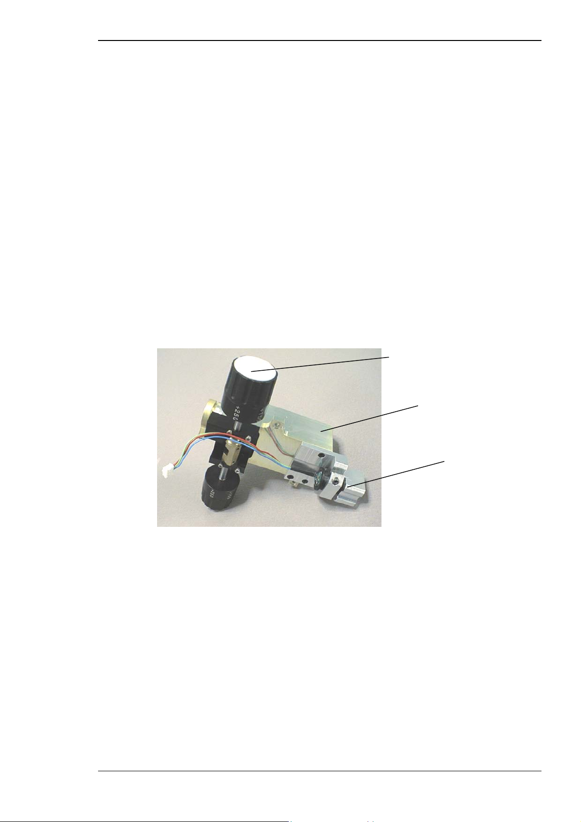
Functional description
The BET module comprises:
⇒ ⇒ positive and negative lenses
optic wedge
This is an optical module that expands the YAG laser beam to the largest
possible size. This results in a decrease in the focused spot size at the
output, which increases the performance of the unit.
The BET module allows the YAG laser focus to be adjusted with respect to
the aiming beam and viewing focal planes in the Z-axis. It also provides a
posterior offset control to the operator.
YAG diode aiming module (DAM)
The YAG treatment beam is aimed by means of a visible red diode laser
beam. This low power laser is coaxial with the YAG treatment beam and is
delivered from the objective lens as dual beams of laser light that are
parfocal with the slit lamp focal plane.
Figure 3–8 Diode aiming module (DAM)
Posterior YAG offset control
BET module
Diode aiming module
The diode aiming module comprises a 635 nm dual beam red diode laser
with integral photodiode, and beam expander.
The beam leaves the module and hits an aiming beam mirror, which reflects
approximately 50%. The remainder is reflected by a second mirror, which is
totally reflective. In each case, the reflected light is coaxial with the
treatment beam. The beam then passes through the objective lens into the
viewing plane.
Small focus adjustments can be made by sliding the DAM up and down
within its holder to ensure the aiming beam is smallest when the system is
focused. Refer to Section 6.7 for further information.
The X-Y position of the aiming beam can be adjusted via the socket screws
on the aiming mirror arms. Refer to Section 6.6 for details.
Tango, Ultra Q and Solo Service Manual 3-11
Issue 2.0
Page 48

Functional description
These adjustments enable you to accurately position the aiming beam on
top of the treatment beam to ensure they are both focused in the correct
plane.
If the treatment and aiming beams are not centred in the illumination slit,
refer to Section 6.3 for instructions.
Laser diode output intensity is controlled using a pulse width modulation
(PWM) control scheme, which:
⇒
monitors the DAM output using the integral photodiode
⇒
sets the laser diode current until the desired output power is
obtained
⇒
controls output intensity by pulsing the diode
⇒
monitors diode current and output power to maintain a constant
output power
If the current or output power deviate outside preset limits an error
is raised and the unit shuts down in a safe condition.
Only one of the system’s two aiming lasers is operational at any time. The
operational aiming laser is the one appropriate for the mode of operation
selected (YAG or SLT).
The intensity of the YAG and SLT aiming beams is controlled by a knob at
the right hand side of the slit lamp base.
YAG folding mirror module (YFMM)
The YAG folding mirror module (see Figure 3–7) reflects the YAG laser and
aiming beam through 90 degrees so that they are coaxial with the
operator’s viewing axis and can exit the system through the objective lens.
The folding mirror also splits the aiming beam into two beams and provides
an adjustment for centring the beams on the bore sight axis.
Note that the SLT treatment beam also passes through the YAG folding
mirror without reflection or deflection.
3-12 Tango, Ultra Q and Solo Service Manual
Issue 2.0
Page 49

Functional description
3.2.5 SLT treatment beam
The SLT (selective laser trabeculoplasty) treatment beam is derived from the
YAG laser module, but it is frequency doubled and beam shaped to provide
the physician with a precise, safe means for performing selective laser
trabeculoplasty.
The YAG attenuator module is also used as a beam switch to direct the
output of the YAG laser module to the SLT optical modules.
The SLT treatment beam produces short, individual pulses of focused green
light with a wavelength of 532 nm and a low energy density spot 400 µm in
diameter.
SLT laser characteristics
The SLT treatment laser has the following characteristics:
⇒ wavelength 532 nm
⇒ high quality pulse of energy up to approximately 2.6 mJ per pulse
(single pulse only)
⇒ 3 ns pulse duration, directed along the optical axis of the system
⇒ spot size 400 µm (calculated 84% energy in this diameter)
⇒ beam divergence <3 degrees (84% included energy)
⇒ single beam diode laser aiming system
SLT laser beam paths
The laser and optics follow three distinct paths:
⇒ treatment beam path — the path of the SLT laser beam used for
treating the patient
⇒ aiming beam path — the path of the red diode laser beam used for
aiming the laser beam
⇒ viewing path — the path from the eye of the patient to the eye of the
operator (see Section 3.2.1)
These paths are described later in this chapter and are illustrated in Figures
3–3 and 3–9. The SLT treatment beam is created in the YAG laser cavity
module, as for the YAG treatment beam. It passes through the optic halfwave plate and into the YAG attenuator, where it is deflected to the
frequency doubling module by a polarising plate.
When the system is in SLT mode, the YAG attenuator is set to maximum
attenuation, which results in nearly all the 1064 nm laser energy being
reflected off the polariser optic and into the frequency doubling KTP
(Potassium Titanyl Phosphate) crystal housed in the frequency doubling
module.
Tango, Ultra Q and Solo Service Manual 3-13
Issue 2.0
Page 50
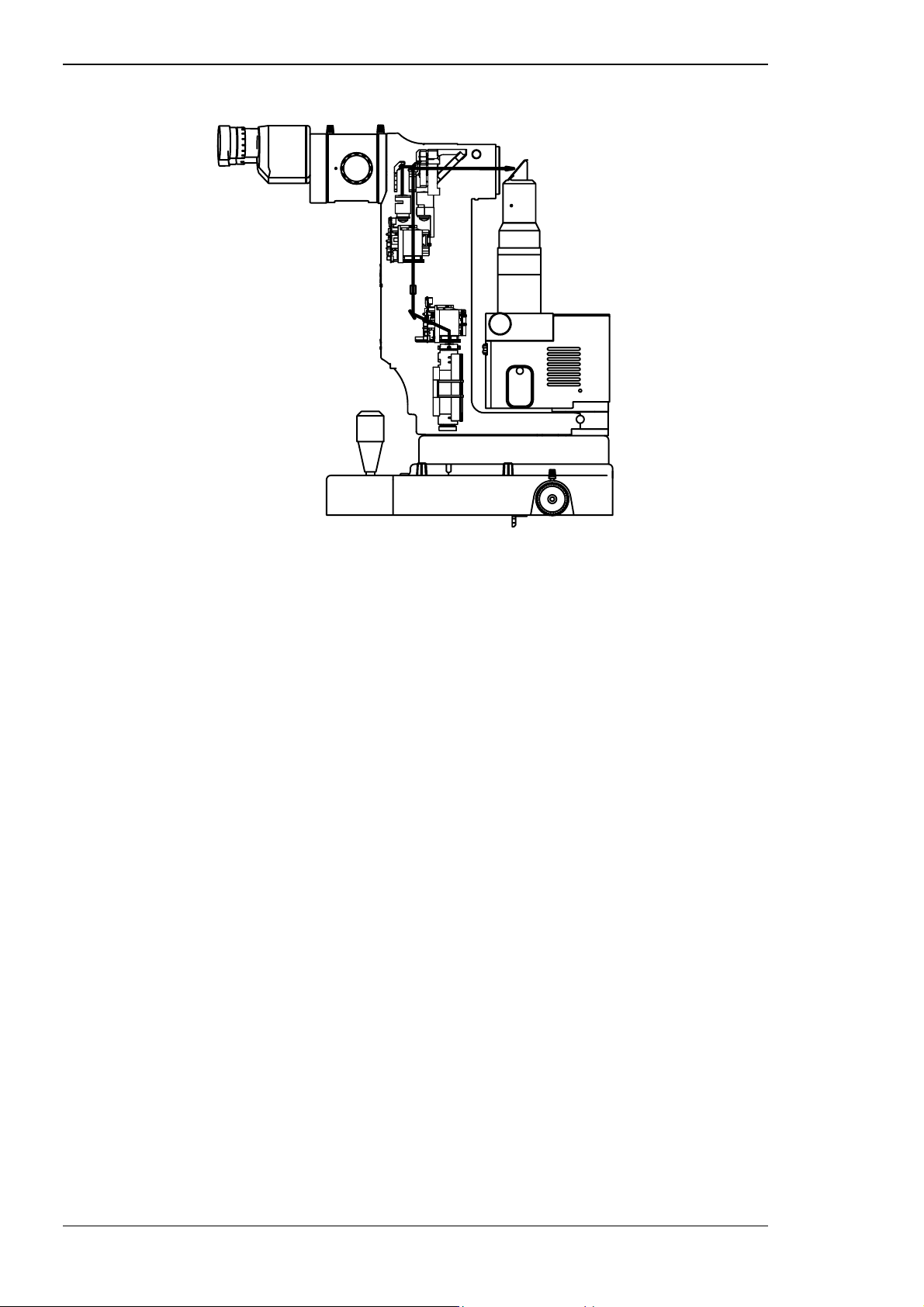
Functional description
Figure 3–9 SLT treatment beam path
Frequency doubling module
The frequency doubling module in the SLT treatment beam optical path
comprises:
⇒
optic lens
⇒
mirror
⇒
KTP frequency doubling crystal
The KTP crystal produces 532 nm pulses, which pass through another
polariser-half-wave plate to allow their energy to be controlled. A beam
splitter splits a portion of the attenuated 532 nm beam onto a photodiode
for energy measurement.
SLT attenuator module
The SLT attenuator module (see Figure 3–6) comprises:
⇒
shutters
⇒
energy meter
⇒
optic beam splitter
⇒
diffuser
⇒
filter
This module optically attenuates the frequency doubled laser output. After
attenuation, a portion of the beam is split by a beam splitter, which samples
off 10% of the beam and directs it into an energy meter to read the energy
level of the attenuated laser beam.
3-14 Tango, Ultra Q and Solo Service Manual
Issue 2.0
Page 51

Functional description
The beam is blocked if the shutter in the SLT attenuator is closed. The
shutter is only allowed to open when READY status is selected.
Energy is selected by the operator, using the ENERGY control knob. After a
treatment laser fire the energy is displayed on the LCD on the control
module. The laser can be fired again after a minimum time of one second.
The total beam block absorbs the incident energy when the shutter is
closed, but when it is open the beam passes through to the SLT folding
mirror module, which deflects it to through the binocular objective lens.
SLT diode aiming module (DAM)
The SLT treatment beam is aimed by means of a visible red diode laser
beam produced by the SLT diode aiming module. This low power laser is
coaxial and parfocal with the treatment beam and is delivered from the
objective lens as a single beam of laser light that is parfocal with the slit
lamp focal plane.
The aiming beam output intensity is controlled in the same way as the YAG
aiming beam.
Only one of the system’s two aiming lasers is operational at any time. The
operational aiming laser is the one appropriate for the mode of operation
selected (YAG or SLT).
SLT folding mirror module (SLT FMM)
The SLT folding mirror module reflects the SLT treatment beam and aiming
beam through 90 degrees so that they are coaxial with the operator’s
viewing axis and can exit the system through the YAG folding mirror
module and objective lens.
The folding mirror module also provides an adjustment for centring the
beams on the bore sight axis.
3.3 POWER SUPPLY CONSOLE COMPONENTS
The power supply console provides power to the laser systems and
provides connections for the control module, which rests on the table.
The power supply console is mounted under the table and comprises two
replaceable modules:
⇒ ⇒ YAG power supply module
switched mode power supply module
Tango, Ultra Q and Solo Service Manual 3-15
Issue 2.0
Page 52

Functional description
3.3.1 YAG power supply module
The power supply converts a 15 V DC input into a High Voltage output for
the YAG laser flash lamp via the trigger module.
The YAG laser operates in single, double and triple pulse modes, as
determined by the voltage levels output from the YAG power supply.
3.3.2 DC switched mode power supply module
The switched mode power supply module provides 15 V DC to the system.
This module accepts a mains input voltage in the range of 90 to 264 V AC.
3.4 TABLE AND STAND COMPONENTS
The table is the platform upon which the laser head and slit lamp are
mounted. It includes a chinrest and may include a drawer mounted on the
underside on the left hand side. The table size is determined by the type of
stand base fitted.
The table is mounted on a motor-driven stand for convenient height
adjustment. The stand column includes the mains inlet, a fused IEC socket
for 100–120 V or 220–240 V AC.
The stand base is available in two versions: Mobile, which has a compact
base with lockable castors for easy relocation, and Access, which is a
wheelchair accessible version. Extension wings are available for both
stands.
3.5 CONTROLS AND FEATURES
Controls are located on the control module, laser head, slit lamp, chinrest
and power supply console.
3.5.1 Control module controls and indicators
The control module can be mounted in either locating hole on the table
extension wings. It is connected to the power control console beneath the
table, and contains a microprocessor, liquid crystal display (LCD) and
keypad. Refer to Figure 3–10. The module is protected by a durable
polycarbonate membrane that provides a sealed, flush surface for
protection and ease of cleaning.
Each tactile push-button on the module beeps when pressed to alert the
operator that a setting has been changed. The volume of the beeps, LCD
contrast and auto-standby time can be adjusted using the Operator menu,
as described in Section 7.6. This menu is also used to select the firing
mechanism.
A number of controls are also provided on the laser head and the slit lamp
base, for ease-of-use during a medical procedure. (Refer to the next sections
for details.)
3-16 Tango, Ultra Q and Solo Service Manual
Issue 2.0
Page 53
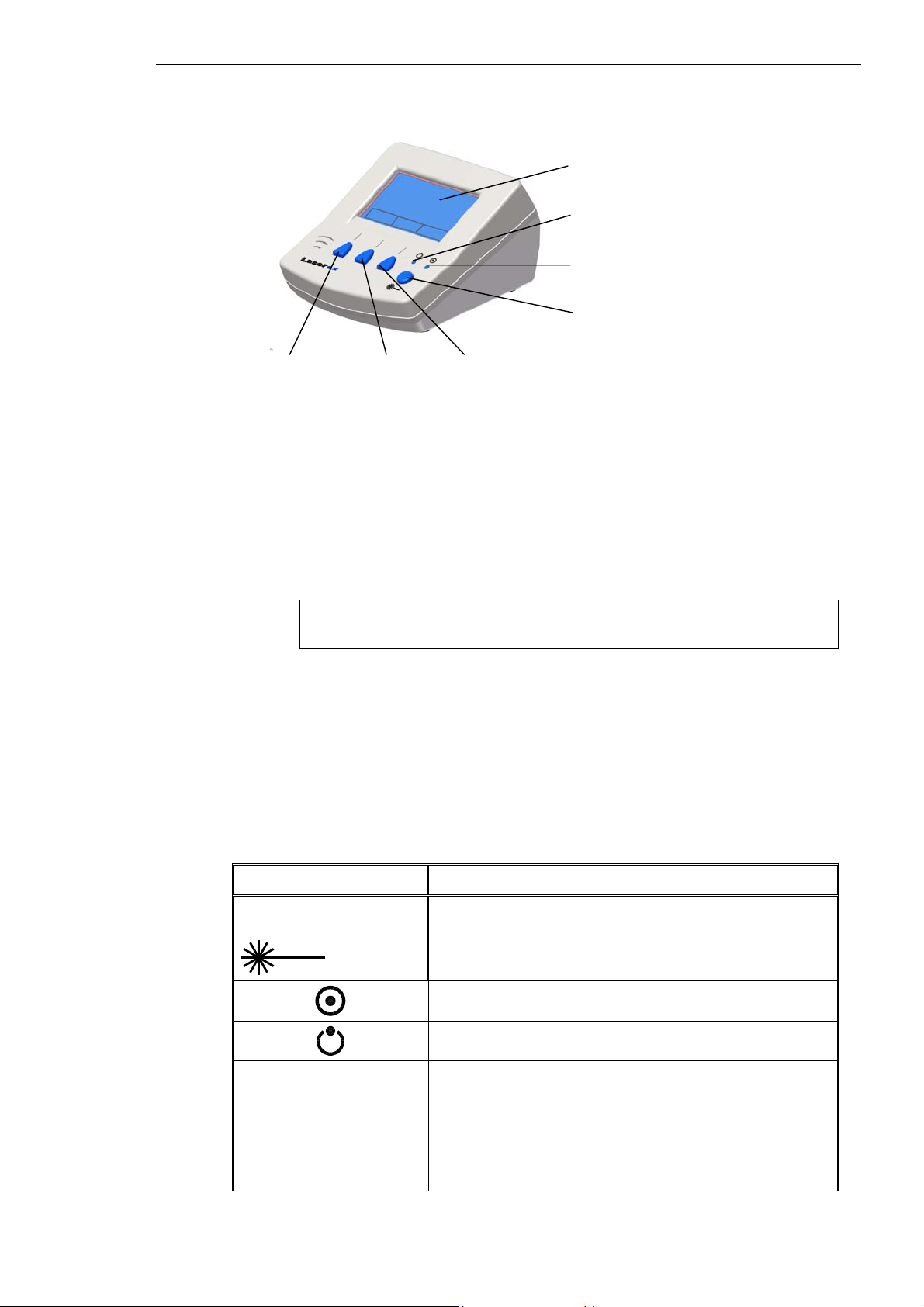
Functional description
Figure 3–10 Control module
LCD
STANDBY status indicator
READY status indicator
READY/STANDBY selection
Pulses Reset Treatment mode selection
The control module controls the system and displays status information. A
communication link allows the transfer of information between the control
module, YAG power supply and laser head modules.
The microprocessor controller mounted inside the control module panel
monitors and controls the function of the critical components. If a fault
occurs, the microprocessor prevents the laser fire switch from functioning
and shows an error code on the LCD. See Section 10.2 for a description of
the error codes.
Extreme cases of electrostatic discharge can cause segments of the LCD to
go blank. If this happens, turn the mains power off then on again.
Controls, indicators and connectors
The control module functions allow the operator to select the treatment
laser and pre-set the treatment parameters before starting a medical
procedure.
Table 3–1 Control module controls and indicators
Control/Indicator Description
Ready/Standby Select
button
PULSES button (Left)
Selects one of two mutually exclusive states: READY
and STANDBY.
READY status LED.
STANDBY status LED.
Selects single, double or triple pulse on YAG
treatment mode. Pressing the button once selects
double pulse, twice selects triple pulse. Only single
pulse is available in SLT treatment mode. A test fire
occurs each time the setting is changed. This button is
disabled in the Solo.
Tango, Ultra Q and Solo Service Manual 3-17
Issue 2.0
Page 54
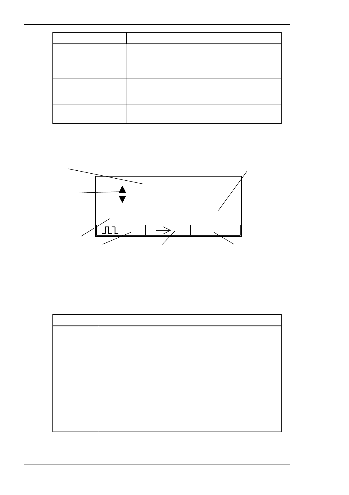
Functional description
Control/Indicator Description
RESET button (Centre)
Treatment Mode
Selection button (Right)
Control module
communication link
Figure 3–11 LCD indications
Energy display Total energy register
Energy deviation
warning indicators
(displayed when
energy deviates by
more than ±20% of
set value)
Total pulses display
2 TOTAL 7mJ
Resets the cumulative energy display and pulses
display. Press before each procedure to ensure the
total energy and number of pulses delivered in a
procedure is displayed.
Selects either the YAG or SLT treatment mode. The
mode is indicated on the LCD. This button is disabled
in the Ultra Q and Solo.
Connection socket for communication link to
console.
3.5 mJ
1
0
YAG
SLT
Sets number of pulses in YAG
mode (1, 2 or 3) (always 1 in Solo)
Table 3–2 LCD indications
(Refer to the illustration above.)
Control Description
Energy display
Pulses display
After power-up the energy of the last test fire is displayed. While
the energy is being adjusted, a prediction of the energy is
displayed and then replaced by the actual energy of the test fire.
When the laser is fired in READY status the measured energy of
each laser burst is monitored. Any deviation greater than ±20%
from the test shot energy is indicated by flashing up/down
arrows in front of the energy value (see Figure 3–11).
If double or triple pulse bursts are selected, the displayed
energy will be the cumulative total of all pulses within the burst.
Shows ‘1’, ‘2’ or ‘3’, indicating the selection of single, double or
triple pulses per shot. (Only single pulse is available in Solo and
in the Tango’s SLT treatment mode.)
Resets pulse count Selects operating mode
Y = YAG, S = SLT (always
YAG in Ultra Q; SLT in
Solo)
3-18 Tango, Ultra Q and Solo Service Manual
Issue 2.0
Page 55
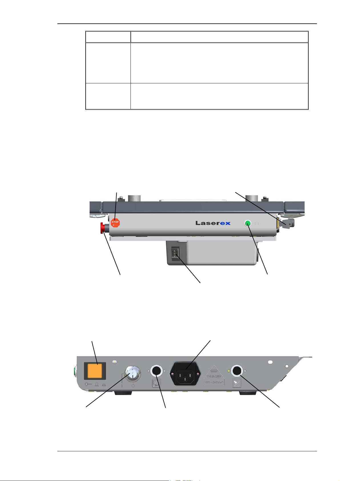
Functional description
Control Description
Total energy
register
The cumulative total energy used during a procedure. The
display is calibrated in millijoules (mJ) and rounded to the
nearest mJ. This display only increments when a treatment shot
is fired, and so indicates how much energy was actually
delivered to the patient.
Pulses total
display
The cumulative total pulses fired. The display increments in
single units in single pulse mode, two units at a time in double
pulse mode, and three units for each shot in triple pulse mode.
3.5.2 Power supply console controls
The power supply console is mounted to the underside of the table. Its
switches, controls and connections are described in the following tables.
The connections are illustrated in Figure 3–16.
Figure 3–12 Power supply console controls & features
Emergency Laser Stop switch symbol Mains power ON/OFF key switch
Emergency Laser Stop switch Mains power ON/OFF indicator
Table UP/DOWN switch
Figure 3–13 Power supply console (right side)
Illuminated Laser ON/OFF switch IEC socket (for connection to the switch box)
Mains power key switch Theatre door interlock connector Footswitch connector
Tango, Ultra Q and Solo Service Manual 3-19
Issue 2.0
Page 56

Functional description
Table 3–3 Console switches and adjustments
Control Symbol Description
Emergency Laser
Stop switch
Mains power
ON/OFF
indicator
Mains power
key switch
Laser system
active indicator
Table raise/
lower (on Switch
box)
This is a red mushroom type push-button. When
pressed in it immediately switches off all power and
eliminates any risk of laser radiation. It must be twisted
a quarter of a turn clockwise to release it and allow
the system to operate.
This green indicator lamp on the front panel is lit when
the system is turned on with the key switch, and
indicates the power is on and the slit lamp is activated.
The key switch is the main power switch. When the
key is inserted and turned to the ON (“|”) position, all
functions are available. The key can only be removed
in the OFF (“O”) position. Note that the system will
not turn on if the Emergency Laser Stop switch has
been pushed in.
This orange push-button is illuminated when pushed in
to the ON position, to indicate the aiming beam(s) are
on and the treatment lasers are available.
Raises or lowers the table to the correct height for the
patient. This is a rocker switch with a spring return to
the centre (OFF) position.
Voltage selector
(on switch box)
To raise the table, push the switch in the direction of
the up arrow. To lower the table, push the switch in
the direction of the down arrow. When the switch is in
the centre, the table remains in position and cannot
move.
Selects the voltage for the local mains supply (120 or
240 V AC).
3-20 Tango, Ultra Q and Solo Service Manual
Issue 2.0
Page 57
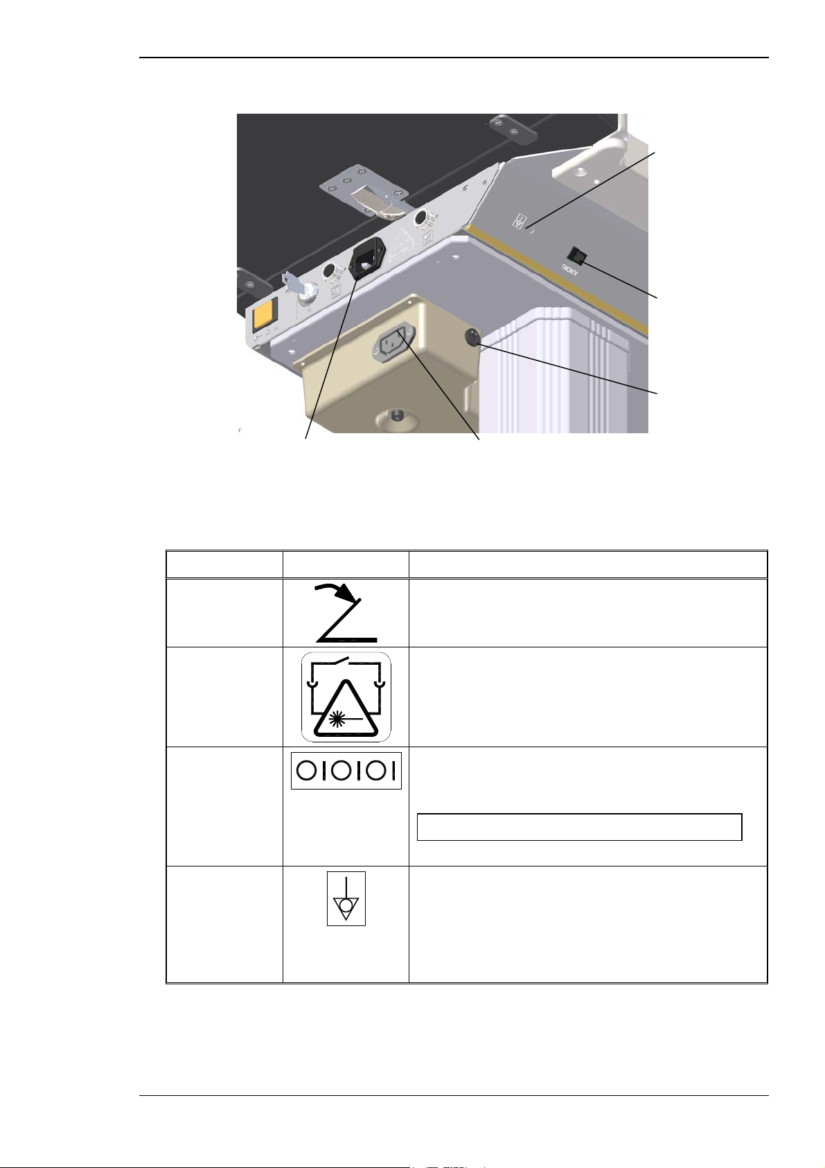
Functional description
Figure 3–14 Console connections
IEC power socket inlet IEC power socket outlet
Equipotentiality
connector
(earth)
Connection to
control module
Voltage
selector
Table 3–4 Console connectors
Connector Symbol Description
Footswitch
connector
Safety interlock
connector
Control module
port
Equipotentiality
connector
Panel mounting electrical connector for optional
footswitch laser fire control.
The safety (theatre door) interlock allows the
operator to install external safety interlocks if
required. The system is supplied with a shorting plug
fitted to the connector to defeat this interlock.
RJ45”telephone” style connector provided on the
console rear to allow the connection of the control
module.
Do not connect other devices to this port.
Potential equalisation conductor. The ESD (electrostatic discharge) wrist strap is connected to the
equipotentiality connector to provide an earth, as
required when working with components sensitive
to electrostatic discharge (such as the
microprocessor and LCD).
Tango, Ultra Q and Solo Service Manual 3-21
Issue 2.0
Page 58
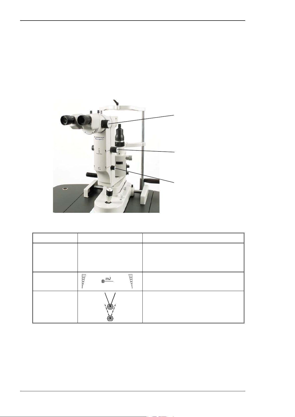
Functional description
3.5.3 Laser head—controls and features
The controls on the laser head have been ergonomically positioned to
minimise operator fatigue and to allow easy adjustment without the need
for the operator to move back from the binoculars. The control module is
placed on the table so that treatment parameters can be checked without
moving back from the binoculars.
Figure 3–15 Laser head
Magnification changer
Posterior YAG offset
(Tango/Ultra Q)
Energy
Table 3–5 Laser head controls
Control Symbol Description
Magnification
changer
Energy
Posterior YAG
offset
A large rotary control on each side of the
laser head and in line with the binoculars.
Used to select three magnification
settings.
A rotary control on each side of the laser
head. Selects the treatment laser energy.
Symbol indicating the YAG posterior
offset control on each side of the laser
head. (This control is not present in the
Solo.)
3-22 Tango, Ultra Q and Solo Service Manual
Issue 2.0
Page 59
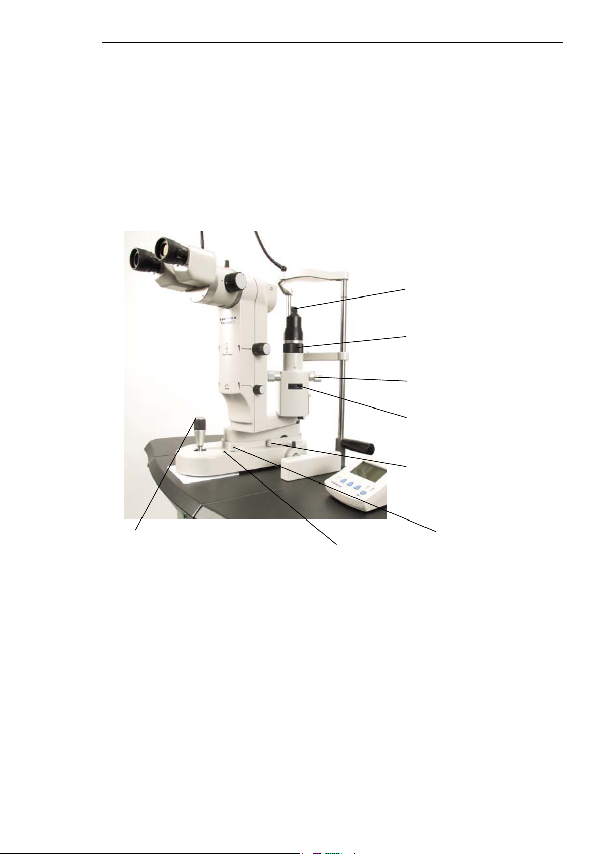
Functional description
3.5.4 Slit lamp—controls and features
The Tango, Ultra Q and Solo slit lamps have been modified from the
standard slimline binocular head support arm and magnification changer, to
a special enlarged support arm containing all the laser optics. All slit lamp
features and controls remain unchanged.
The system is supplied with fixed magnification of 16 x using 12.5 x
eyepieces. A three-step magnification changer is fitted between the
binocular head and the support arm (see Figure 3–17).
Figure 3–16 Slit lamp
Illumination beam splitter
Slit rotation
Slit lamp slit width control
Filters and apertures
Aiming beam intensity
Joystick Illumination intensity
and fire button Illumination boost (push-button)
Tango, Ultra Q and Solo Service Manual 3-23
Issue 2.0
Page 60
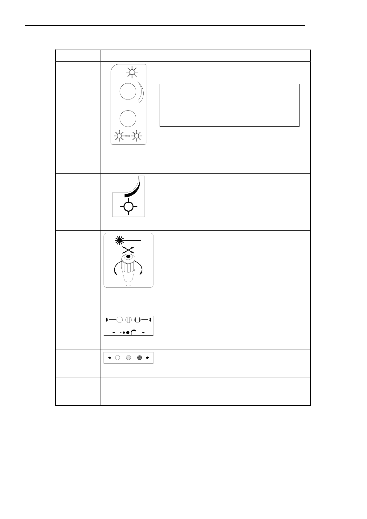
Functional description
Table 3–6 Slit lamp controls
Control Symbol Description
Slit lamp
intensity
Slit lamp
intensity
boost button
Aiming beam
intensity
XYZ joystick
and laser fire
button
A rotary control on the right hand side of the slit
lamp base. Adjusts the slit lamp intensity.
Note: If high illumination is not required, the
lamp should be kept at minimum intensity to
reduce heat build-up. Do not leave the
illumination intensity at maximum for more
than ten minutes.
A push-button on the right hand side of the slit
lamp base, adjacent to the slit lamp intensity
control. Pressing and holding this button briefly
boosts the slit lamp intensity to maximum.
A rotary control on the right hand side of the slit
lamp base. Adjusts the red aiming beam intensity.
Used to manipulate the position of the laser head
and slit lamp. The unit moves in the direction that
the joystick is pushed, either left/right or forward/
back.
Slit lamp
control
Illumination
aperture
Filters
Slit rotation
The height of the unit is adjusted by rotating the
joystick. The push-button on the top of the joystick
can be used to fire the laser unless the footswitch
is connected.
A rotary control on each side of the illumination
tower adjusts the slit width.
Top wheel on the front of the illumination tower.
Selects the aperture. 0.5, 5, 8, and 12 mm and a
variable aperture are available.
Bottom wheel on the front of the illumination
tower. Used to select a blue, green, or neutral
density (ND) filter.
Knurled black section of the illumination tower.
Turned to rotate the slit 90 degrees either side of
vertical.
3-24 Tango, Ultra Q and Solo Service Manual
Issue 2.0
Page 61

Functional description
Control Symbol Description
Illumination
tower
Laser head
Eyepiece
adjustment
The illumination tower can be rotated
approximately 90 degrees either side of the centre
position.
(Tango only) Tower rotation is monitored via an
interlock. If the slit lamp is in line with the
objective lens and the unit is in YAG status, the
unit beeps, a warning message appears on the
LCD, and the aiming laser beams flash until the
tower is rotated out of the treatment beam path.
No laser emission is allowed until this condition is
rectified.
(Ultra Q and Solo) The tower interlock is fitted but
not enabled, since the Ultra Q has a lower prism
which does not obstruct the YAG aiming or
treatment beams.
The laser head can be rotated approximately 20
degrees either side of the centre position.
Dioptre adjustment is provided on both eyepieces
to allow the binocular focus to be adjusted for
each operator. The eyecups can be pushed back if
the operator wears spectacles.
Interpupillary
distance
The eyepiece positions can be adjusted to suit the
operator’s interpupillary distance.
adjustment
Illumination on/off
The halogen lamp illumination is controlled by the key switch on the power
supply console panel.
Fire switch
The fire trigger switch is located on top of the joystick. This switch is only
active when all the following conditions are met:
⇒ key switch in the ON position
⇒ Emergency Laser Stop switch in the ON position (released)
⇒ system in laser READY status
The fire switch should be released quickly after each firing action. If not, the
system will automatically return to STANDBY status giving an audible
warning. The system can be manually returned to READY status once the
fire switch has been released.
Caution
When the fire switch is pressed, with the unit in laser READY status,
dangerous laser radiation is emitted from the aperture.
Tango, Ultra Q and Solo Service Manual 3-25
Issue 2.0
Page 62

Functional description
Interpupillary distance adjustment
The separation of the eyepieces is adjustable to suit the interpupillary
distance of the user.
Adjusting the eyepieces
Adjust the slit lamp binocular eyepieces to suit as follows:
Look only into the eyepiece with the crosshair and turn the
eyepiece adjusting ring clockwise then anticlockwise until the
crosshair appears as sharp as possible.
While looking through the eyepiece with the crosshair, move the
target on the alignment jig backwards and/or forwards until the
target is seen as clearly as possible.
Look through the eyepiece with no crosshair and turn the eyepiece
adjusting ring until the target is seen as clearly as possible.
3.5.5 Chinrest controls
The following controls are available for chinrest adjustment:
Table 3–7 Chinrest adjustments
Control Description
Chinrest height The black collar on the chinrest post can be
rotated to adjust the chinrest height.
Adjusting the chinrest
Adjust the chinrest height for the patient's eye by rotating the chinrest
height adjustment knob. Align the eye of the patient between the marks on
the chinrest support.
Hand rest
The patient hand rests are mounted to the left and right sides of the chinrest
supports. The hand rests also provide the method of securing the chinrest
supports.
3-26 Tango, Ultra Q and Solo Service Manual
Issue 2.0
Page 63
4.1 ELECTRICAL SYSTEM DESCRIPTION
This section describes the electrical functions, electronic functions, and
event sequences of the Laserex Tango, Ultra Q and Solo.
4.1.1 Electrical power cord
The Laserex Tango, Ultra Q and Solo are fitted with an IEC approved
hospital grade power cord connection socket in the base.
C HAPTER 4
ELECTRICAL SYSTEM
The system may be provided with a mains electricity lead that is not
terminated. A qualified electrician should terminate this lead using a
locally approved plug. The power cord may be held in place with a metal
strain relief to ensure the cord is not accidentally dislodged from the
connector. To remove the power cord, lift the strain relief.
4.1.2 Theatre door interlock
The interlock is an optional accessory, and therefore not normally supplied.
The interlock socket is located on the side of the power supply console (see
Figure 3–15).
The interlock is a safety feature. If the interlock is fitted and the theatre door
is opened, the treatment and aiming beam lasers are disabled and the
shutter is closed. A beeper in the unit sounds until the door is closed. The
controls and lasers will not function until after the interlock connection is reestablished and the system is in STANDBY status.
A pre-wired DIN plug is supplied to act as a blanking plug if the interlock is
not required. If the theatre door interlock is to be installed, the blanking
plug is removed and a standard DIN plug is connected and wired to a
microswitch circuit fitted to the room door. The circuit diagram is shown in
Figure 4–1.
Tango, Ultra Q and Solo Service Manual 4-1
Issue 2.0
Page 64
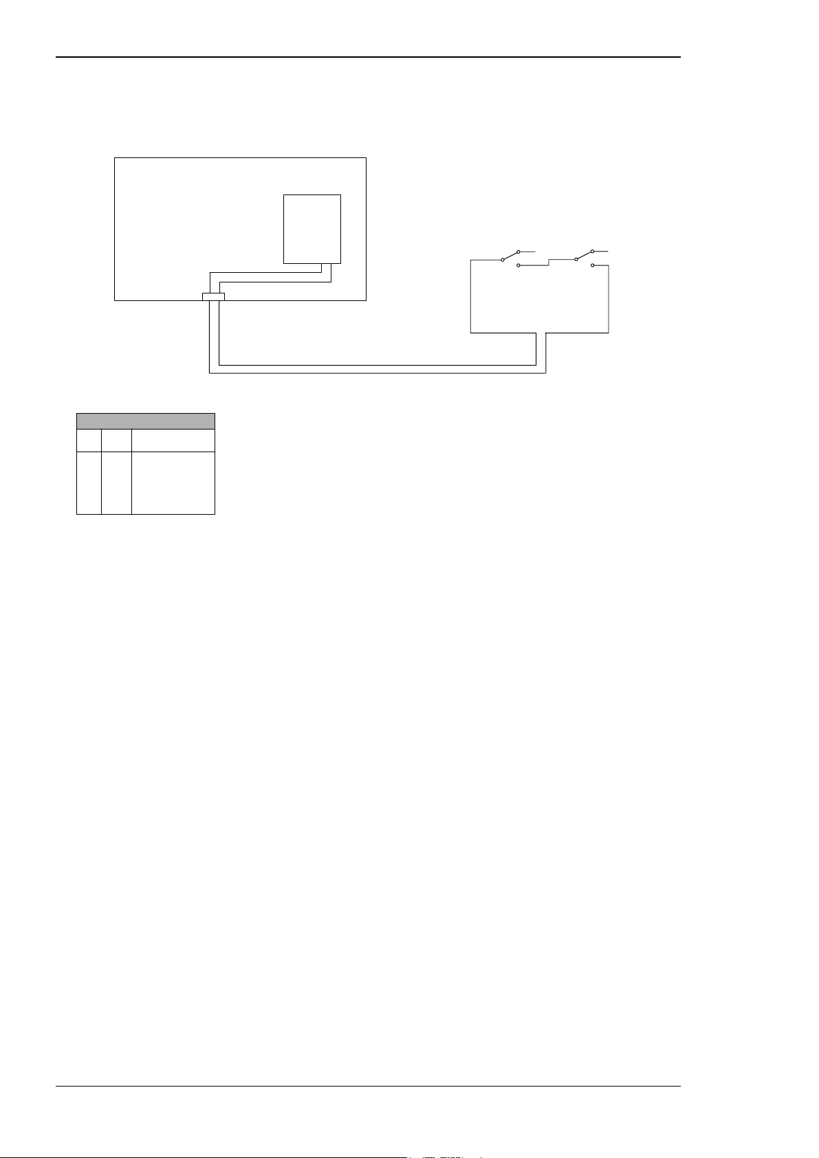
Electrical system
Figure 4–1 Interlock circuit diagram
EXTERNAL
INTERLOCK
INTERLOCK LOGIC
S1 S2 LASER ENABLED
NO
NO
NC
NC
NO
NC
NO
NC
YES
NO
NO
NO
CONSOLE
EXT ILK 1
EXT IKL 2
USER SUPPLIED CABLES AND SWITCHES
FIRE
CONTROL
BOARD
NC
(R)12
(O)13
X4
NOTES: 1. CABLE TO BE WIRED TO CONNECTOR AND
SWITCH BY AN ELECTRICIAN (RECOMMENDED)
2. MICROSWITCH OMRON VX56-1A3 OR SIMILAR
(RECOMMENDED)
3. CABLE 2-CORE SHIELDED 18-22 AWG (RECOMMENDED)
S1 S2
NO
NC
NO
4.1.3 Footswitch connector
The footswitch connector allows the Laserex Tango, Ultra Q and Solo to be
fired using the optional footswitch instead of the joystick. When a
footswitch is connected and selected from the Operator menu (see Section
7.6, the joystick fire switch is disabled.
4-2 Tango, Ultra Q and Solo Service Manual
Issue 2.0
Page 65

Electrical system
4.2 START-UP AND INITIALISATION PROCESSES
The following self-testing and initialisation steps occur when the key switch
is turned ON and the Laser ON/OFF switch is pressed in to the ON
position. They are controlled and monitored by the microprocessor.
⇒
the LCD comes on and displays a welcome message and system
version number for two seconds
⇒
the system is set to single pulse mode (YAG treatment laser in
Tango and Ultra Q or SLT in Solo) and displays the current energy
setting
⇒
the microprocessor checks that the shutter is closed
If the shutter is open, the microprocessor shuts down the treatment
laser system and displays an error code.
⇒
if the shutter is closed the microprocessor checks that the Nd:YAG
storage capacitor is charged
⇒
as soon as the capacitor is fully charged the power supply sends a
‘charging complete’ signal to the microprocessor
⇒
the microprocessor sends signals ordering an auto test fire of a
series of test shots to be fired
The shutter is closed during test firing.
⇒
the sampled energy from the last test fire is displayed on the LCD
⇒
the microprocessor checks for fault conditions
⇒
if any fault condition is detected, the system shuts down and an
appropriate error code is displayed
⇒
the microprocessor checks the aiming laser detector signal to
ensure the aiming laser is operational
After performing the initial set up and test fire described above, the
microprocessor continually monitors the following:
⇒ the four display controls
⇒ treatment energy selection
⇒ aiming laser detector signal
⇒ pulse selection
⇒ fire switch operation
If the operator changes any of these controls, the microprocessor detects
the change and responds accordingly.
The aiming laser detector signal is a status signal, which is not controlled by
the operator. It is a safety feature to ensure the treatment laser cannot be
fired if the aiming laser is not operational.
Tango, Ultra Q and Solo Service Manual 4-3
Issue 2.0
Page 66

4.3 FIRING PROCESSES
When the start-up and initialisation processes are complete and all required
conditions are met, READY status must be selected to enable firing. The
laser is fired by pressing the fire switch on the joystick or pressing the
footswitch, if installed. Whenever an attempt is made to fire, the following
processes occur:
⇒
the microprocessor reads READY status is selected
⇒
the microprocessor reads the fire instruction
⇒
the microprocessor sends a ‘fire’ signal to the trigger module
⇒
the trigger module sends a high voltage trigger pulse to the flash
lamp in the YAG laser
Two sensors inside the SLT or YAG attenuator module (as selected)
detect the shutter position. If the shutter malfunctions the
microprocessor shuts down the power supply, disables the unit and
displays an error code.
⇒
the flash lamp converts the energy in the storage capacitor into a
flash of light
Electrical system
⇒
this flash in turn energises the laser rod
⇒
the shutter motor opens the shutter
⇒
the Nd:YAG cavity outputs a pulse(s)
⇒
the shutter motor then closes
4-4 Tango, Ultra Q and Solo Service Manual
Issue 2.0
Page 67

INSTALLATION AND COMMISSIONING
5.1 INSTALLATION PROCEDURES
The installation described here assumes the unit has been delivered to the
location where it will be unpacked, assembled and used. Installation may
only be carried out by Authorised Laserex personnel.
Installation takes place in the following stages:
⇒
checking the shipping carton and unpacking the contents to
determine if any damage has occurred during shipping
⇒
assembling the unit
C HAPTER 5
⇒
commissioning the unit
⇒
completing the installation check list and service report (included in
Appendix C and in the shipping container) and returning them by
fax to the Ellex Medical Service Department
5.2 TOOLS AND MATERIALS
The following tools and materials are recommended for the installation,
commissioning and servicing of the Laserex Tango, Ultra Q and Solo:
⇒ ⇒
chinrest ophthalmic target Philips head screwdrivers; small,
⇒ ⇒
offset alignment jig flat blade screwdrivers; small,
⇒ ⇒
special 2 mm Allen key jeweller’s flat blade screwdriver
⇒ ⇒
spare Tango, Ultra Q or Solo
binocular offset jig
⇒ ⇒
metric Allen key set medium adjustable spanner
⇒ ⇒
wrist band, anti-static kit penlight torch
⇒ ⇒
collet knob tool burn paper
⇒ ⇒
model eye, fundi red distilled or sterile water
⇒ ⇒
model eye container of AR grade methanol
⇒ ⇒
model eye membranes cotton buds such as Q-tips
⇒ ⇒
calibrated laser energy meter optical lens tissues
⇒ ⇒
voltmeter with 1000 V DC range
and leads
medium and large
medium and large
modified 5 mm nut driver
silicon adhesive (Silastic or
equivalent)
Tango, Ultra Q and Solo Service Manual 5-1
Issue 2.0
Page 68

5.3 UNPACKING
Installation and commissioning
Caution
Caution
Only authorised Laserex personnel are permitted to unpack the unit from
its shipping carton.
Unauthorised opening of the carton will void the warranty.
If the unit has been unpacked by unauthorised personnel, record this on the
commissioning sheet. Under such circumstances the warranty is
provisionally voided and the matter should be referred to the factory for
discussion with the customer. If no damage or loss is evident you may
continue with the installation if the customer accepts the voided warranty.
The customer's signed acceptance of the voided warranty is required.
Before unpacking the unit, inspect the shipping carton for any signs of
damage. If damage exists, contact the freight company and Laserex to make
arrangements to allow the installation to proceed with the minimum of
delay.
Refer to the list of contents supplied with the equipment while unpacking
the contents, and inform Ellex Medical if any discrepancies are found.
Take extreme care throughout unpacking and installation procedures not
to jar the optical assembly or scratch any paintwork.
Retain the shipping carton, boxes and packing materials as these may be
used for later transportation.
5.4 STAGES IN ASSEMBLY
The equipment is assembled in the following stages:
⇒
assemble the table and column
⇒
check mains voltage
⇒
locate and securely mount the table on the stand plate
⇒
assemble the chinrest
⇒
assemble the optical components and control module
⇒
connect the safety interlock
⇒
connect to mains power
Refer to Figure 5–1 during installation.
5-2 Tango, Ultra Q and Solo Service Manual
Issue 2.0
Page 69
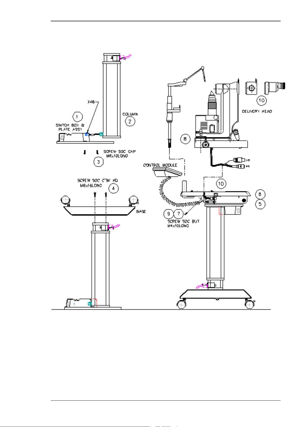
Installation and commissioning
Figure 5–1 Installation diagram
Tango, Ultra Q and Solo Service Manual 5-3
Issue 2.0
Page 70
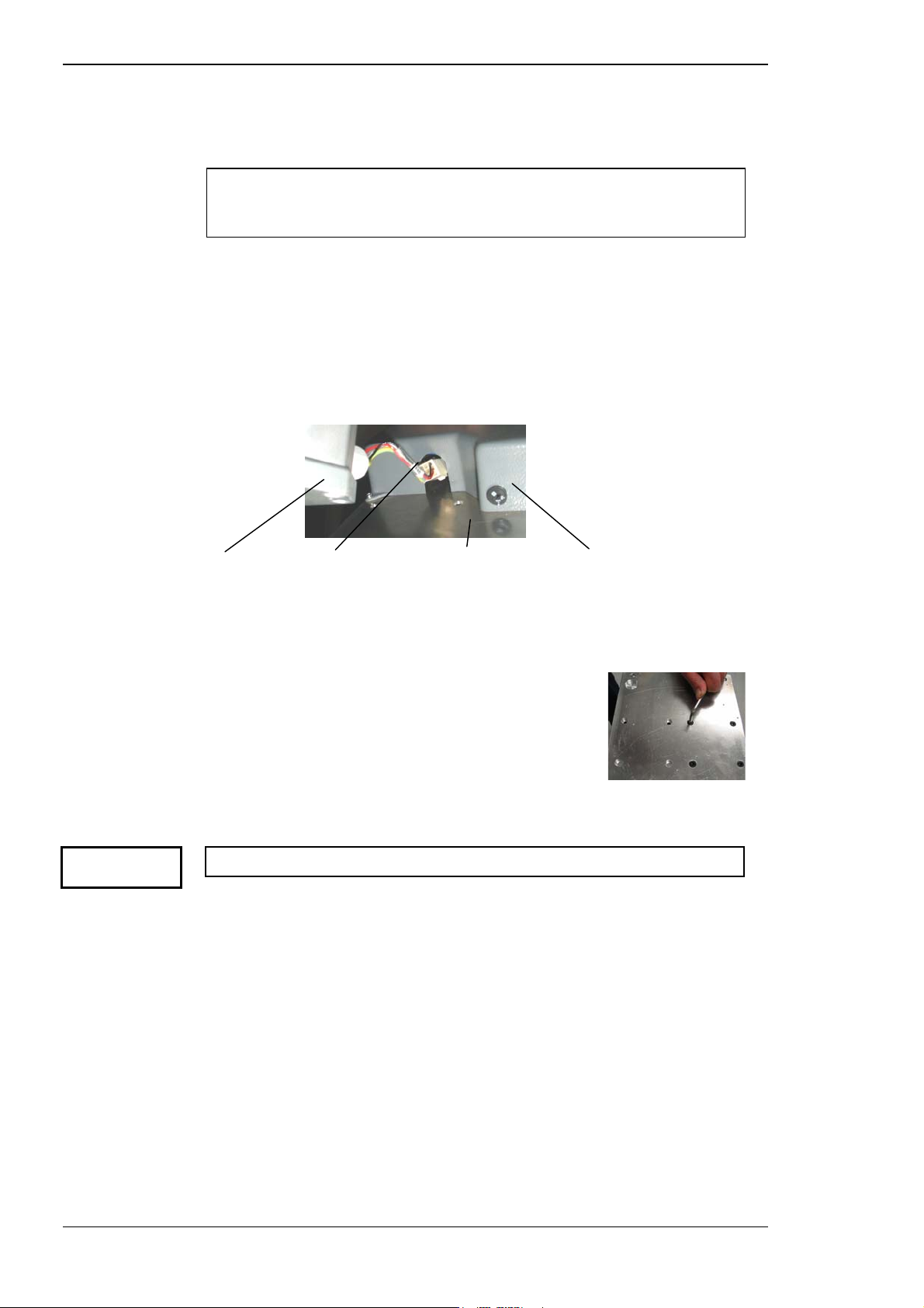
5.5 ASSEMBLING
The system is shipped with the base and top plate disassembled.
Photographs included in these instructions are of the Access (wheelchair)
stand. The Mobile stand is assembled in exactly the same way, except as
noted.
5.5.1 Attaching the top plate
Attach the top plate to the top of the column as follows:
Place the switch box and top plate down on a desk.
Ensure the X48 connector extends from the side of the switch box
Installation and commissioning
Caution
Column top X48 cable Top plate Switch box
Connect the X48 cable to the connector at the top of the column.
Turn the column and top plate over, then:
Fasten the plate to the column using the
four long M6 screws, as shown.
5.5.2 Checking mains voltage
Do not plug in the unit until you have confirmed the correct voltage.
The laser system is powered from either a 100 - 120 V AC or
220 - 240 V AC supply. Before continuing the assembly, ensure the
operating voltage of the unit is compatible with local mains voltage.
If the operating voltage is incorrect for the local supply, change the voltage
setting as follows:
Ensure the system is turned off and disconnected from the mains.
Using a slotted screwdriver, rotate the voltage selector switch at the
top of the stand column (at the same side as the inlet socket — see
below) to align the arrow with the required voltage.
5-4 Tango, Ultra Q and Solo Service Manual
Issue 2.0
Page 71
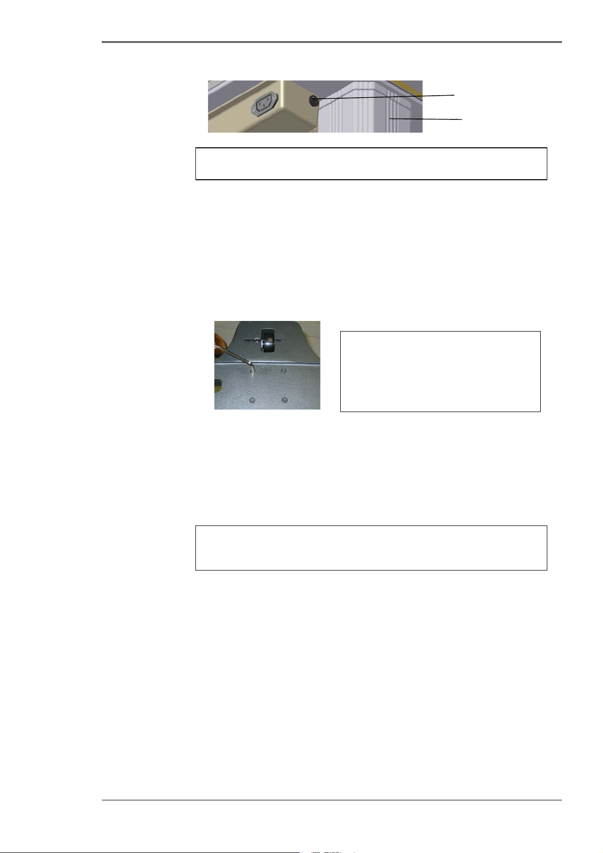
Installation and commissioning
Figure 5–2 Voltage selection
Voltage selector
If changing the mains voltage after assembly, switch the system off and
unplug from the mains before changing.
5.5.3 Fitting the base
The bases of the Access and Mobile are fitted in the same way, as follows:
Turn the assembly over on the floor, resting on the top plate.
Fit the base with the four short M6 screws as shown, ensuring the
base is in the correct orientation.
The Table Up/Down switch on the
switch box faces the doctor, so in the
Access, the ‘horns’ are on the opposite
side to the switch, and in the Mobile,
the locking castors are on the same
side as the switch.
Stand column
5.5.4 Fitting the power cord
The power cord connects to the mains inlet at the bottom of the column in
both the Mobile and the Access. The plug may be held in place with the
metal strain relief to ensure the cord is not accidentally dislodged from the
connector.
The system may be provided with a mains electricity lead that is not
terminated. A qualified electrician should terminate this lead using a
locally approved plug.
To remove the power cord, lift the strain relief.
Attach to the mains only when the laser system is completely assembled.
Tango, Ultra Q and Solo Service Manual 5-5
Issue 2.0
Page 72
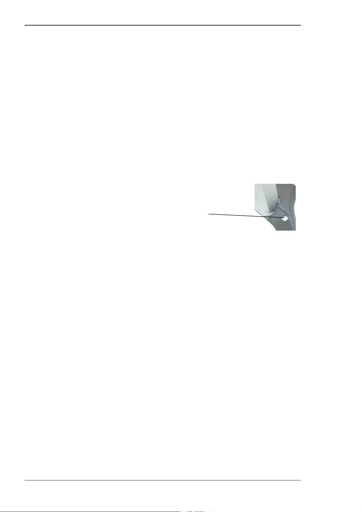
Installation and commissioning
Mobile stand
In the Mobile stand:
Attach the power cord to the socket at the base of the column.
Run the cable under the base and secure using one of the clips,
which will direct the cable out from one of the sides of the base and
away from the patient’s feet.
Ensure the cable to the mains outlet is positioned where it cannot
be damaged or crushed, and is not in the way of the patient.
Lift the stand into its upright position.
Check and level the castors if required.
Access stand
In the Access stand:
Attach the power cord to the socket at the base
of the column.
Feed the cable under the stand base through the
access hole beside the column.
Secure in position under the base with the two
plastic clips, taking care not to trap your fingers.
Push the power cord cover into place over the power cord access
hole.
Ensure the cable to the mains outlet is positioned where it cannot
be damaged or crushed, and is not in the way of the patient.
Lift the stand into its upright position.
5.5.5 Assembling the power supply console and table
With the stand in its upright position:
Check and level the castors as required.
Place the console/table assembly on the plate and fasten in place
with the four captive screws.
Open the rear flap on the console.
5-6 Tango, Ultra Q and Solo Service Manual
Issue 2.0
Page 73
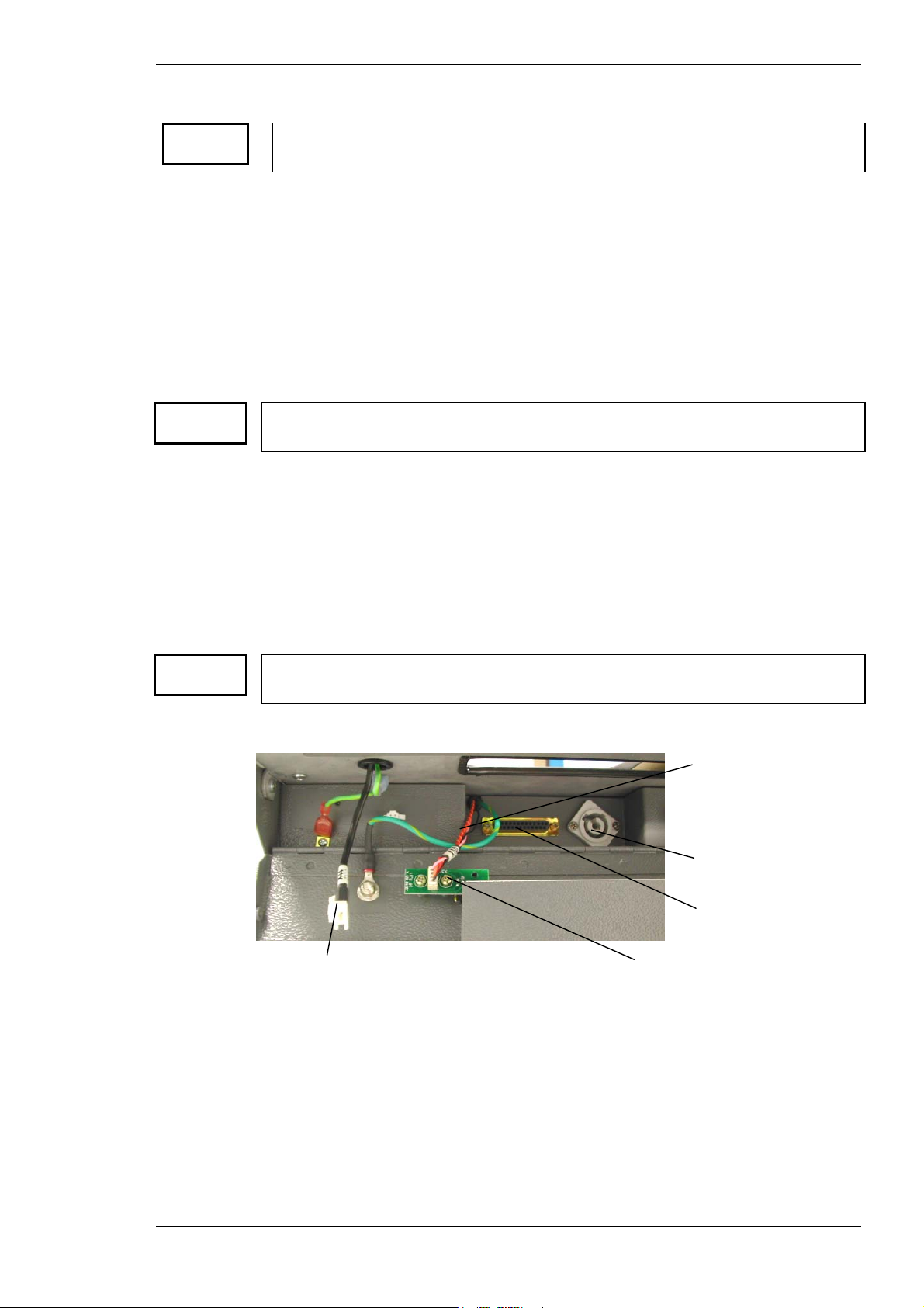
Installation and commissioning
5.5.6 Assembling the laser head and slit lamp
Caution
Caution
Take extreme care throughout the following procedures not to jar the optical
assembly or scratch any paintwork.
Assemble the optics as follows:
Gently unpack the laser head and slit lamp.
Remove the cross slide shaft from the foam container.
Remove one of the black gearwheels using the Allen key provided.
While holding the laser head, feed the cross slide through the base
of the slit lamp (ensuring the locking screw is not blocking the
shaft).
Re-attach the second gearwheel to the shaft.
Ensure the gearwheel is correctly keyed into the slot in the end of the cross slide
shaft before tightening the screw.
Lower the slit lamp assembly onto the table and locate the cross
slide gears on the gear tracks, which are supplied already mounted
on the tabletop.
Hold the laser head above the centre of the table and feed the two
cables through the slot in the right hand side of the metal tray under
the hole in the tabletop, and on to the power supply console area.
Caution
Connect the high voltage and signal cables to the power supply
console as shown in Figure 5–3.
Make sure the X43 connection is fully pushed in, then rotate clockwise until it
clicks.
Figure 5–3 Power supply console connections
High voltage
connector (X43)
X45 ‘D’ connector
Fixation lamp connector
Push the fixation lamp connector (X44) into its socket.
Push the high voltage connector (X43) into its socket and turn it
Control module connector
until it locks into position.
Push the 'D' connector (X45) into its socket in front and finger-
tighten the side retaining screws.
Ensure the excess cable length is pushed in on the right side so it
does not get caught by the console flap being closed.
Close the console flap and fasten in place.
Tango, Ultra Q and Solo Service Manual 5-7
Issue 2.0
Page 74

Installation and commissioning
Checking the slit lamp
The slit lamp must be able to move freely without catching on the cables:
Ensure the cross slide locking screw on the right hand side of the
delivery head base is loosened, then check that the slit lamp can
move smoothly in all directions without catching on the cables.
Push the gear covers over the cross slide track on each side.
Assembling the binoculars to the slit lamp
Attach the binoculars to the slit lamp and secure with the locking
screw.
5.5.7 Assembling the chinrest
To assemble the chinrest:
Mount the chinrest posts into the brackets fixed to the tabletop,
ensuring the chinrest is in the correct orientation.
Fasten the posts in place by rotating the handles.
Ensure the chinrest cup can be raised and lowered smoothly.
5.5.8 Fitting the extension wings
To fit the extensions to the table:
Insert the first wing locating shaft into the slot in the table side,
ensuring the wing is in the correct orientation.
Clip the extension wing into place.
Repeat for the remaining extension wing.
Fit the drawer into its slide in the extension wing on the doctor’s
left.
5.5.9 Connecting the control module
To install the control module:
Connect the telephone-style connector to the socket marked
on the underside of the control module, and feed the cable through
the mounting pin.
Hold the control module above the locating hole in either extension
wing and feed the connection cable through the hole.
Fit the control module mounting pin into the locating hole.
Insert the telephone-style connector into its socket in the power
supply console (marked:
Ensure any excess cable is not in the patient’s way.
Lift the power supply console back into position and screw in place.
5-8 Tango, Ultra Q and Solo Service Manual
Issue 2.0
).
Page 75
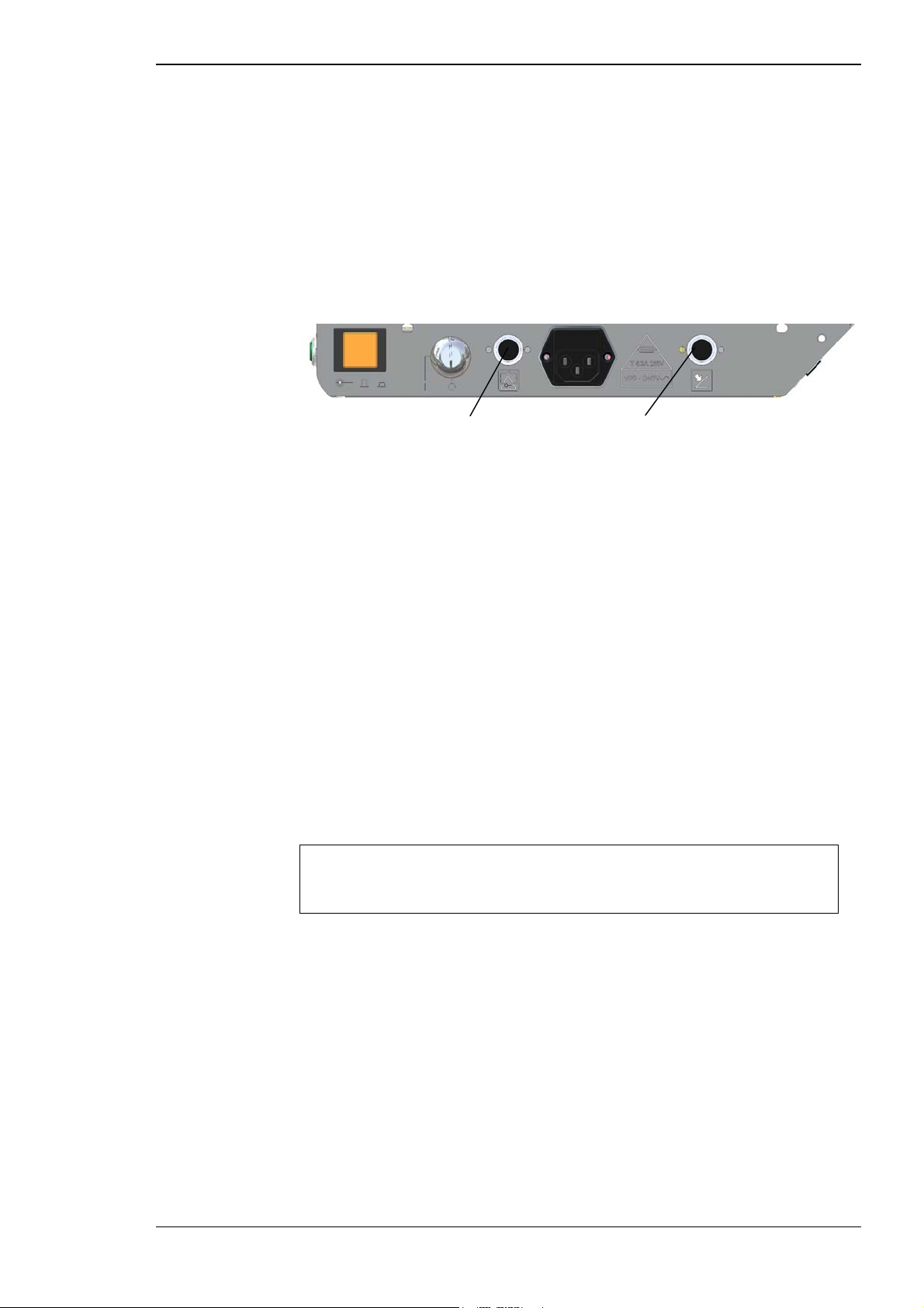
Installation and commissioning
5.5.10 Installing the footswitch (if ordered)
If the optional footswitch has been purchased, install it as follows:
Position the footswitch on the floor where it is convenient for the
user.
Position the footswitch cable where it will not be at risk of being
crushed and attach it to the footswitch connector on the right side
of the power supply console (see below).
Figure 5–4 Footswitch and interlock connections
Interlock connection Footswitch connection
5.5.11 Installing the safety interlock or plug
The Laserex Tango, Ultra Q and Solo are all fitted with an interlock
connector on the right side of the power supply console.
The safety interlock connector is factory installed with a blanking plug. If the
blanking plug is not fitted the system will beep continuously until the
blanking plug is installed. The customer is responsible for deciding how the
system is to be interconnected.
To connect to an external safety interlock door switch, the blanking plug
must be removed and the switch connected using a suitable two-core cable
(such as two-core mains figure-eight flex or speaker wire).
If the theatre door interlock is not installed:
Ensure the blanking DIN plug is installed in the interlock connector
(see Figure 5–4), and fastened down with the screw collar.
The safety interlock should only be bypassed on customer request, and
the customer must accept responsibility for that decision. Make a note to
this effect on the acceptance sheet.
If the interlock is to be installed:
Remove the blanking plug.
Install a DIN plug wired to a microswitch circuit fitted to the room
door (see the circuit diagram in Chapter 4).
Tango, Ultra Q and Solo Service Manual 5-9
Issue 2.0
Page 76

Installation and commissioning
5.6 TESTING THE SYSTEM
Apply mains power and turn the system on using the key switch. When the
system is turned on check that the following actions occur:
⇒
the green power-on indicator lamp on the front of the console is
illuminated
⇒
the green fixation lamp on the chinrest is illuminated
⇒
the slit lamp illumination turns on
Press the Laser On/Off switch and check that the following actions occur:
⇒
the STANDBY indicator LED on the control module is illuminated
⇒
the LCD screen displays the following:
→ a chequered image (brief) over the entire display
→ Laserex logo
→ laser model and version numbers
⇒
the system performs a test routine, during which a series of clicks
will be heard as test shots are fired with the shutter in the closed
position
⇒
when the test routine is completed the LCD displays the following:
→ a graphic of the activated firing mechanism (joystick or
footswitch)
→ normal operating display
The instrument is now installed, and the commissioning checks should be
carried out, as described in the following section.
5.8 COMMISSIONING CHECKS
The following checks should be carried out to verify the system is operating
satisfactorily:
⇒
stand column check
⇒
aiming accuracy check
⇒
air breakdown check
⇒
burn pattern check (YAG)
⇒
SLT performance check
⇒
energy monitor check
⇒
optical alignment check
5-10 Tango, Ultra Q and Solo Service Manual
Issue 2.0
Page 77

Installation and commissioning
5.8.1 Checking the stand column
The stand column has a motor-driven electric lift mechanism for raising and
lowering the table. The motor, drive gearbox mechanism and mains input
voltage connection are all in the bottom of the stand. To check the stand
column:
Press the Table Up/Down switch on the switch box to ensure the
table rises and lowers smoothly and freely.
Ensure there is no twisting motion of the table.
5.8.2 Checking aiming accuracy
Refer to Section 6.6 for instructions.
5.8.3 Checking air breakdown
The air breakdown check is a quick way of evaluating the Nd:YAG laser
performance. Refer to Section 6.7.7.
5.8.4 Checking YAG beam burn pattern (Tango/Ultra Q)
The laser systems should be fully operational before this check is carried
out. Using burn paper affixed to a target, make an out-of-focus burn at
maximum energy using the YAG treatment laser. Check the burn pattern
produced by the laser is circular.
If the pattern is non-circular to a major extent, the YAG system may be out
of alignment and should be re-aligned or returned to the factory for realignment.
5.8.5 Checking SLT performance (Tango/Solo)
This test uses a standard fundus (model retina) but it should be reasonably
fresh as the test is dependant on the pigmentation of the fundus. A faded
fundus is likely to indicate poor performance.
To test SLT performance, ensure SLT mode and READY status are selected,
then fire the laser five times at each of the energy settings in the table
below. The expected results are indicated.
Table 5–1 SLT performance test
Energy setting
(mJ)
0.3 Purple patches
0.5 Partially yellow
1.0 Mostly yellow; some black
Tango, Ultra Q and Solo Service Manual 5-11
Issue 2.0
Burn pattern expected
At all settings, all burn
patterns should be
roughly uniform with no
hot spots.
Page 78

Installation and commissioning
5.8.6 Checking the YAG laser energy monitor (Tango/Ultra Q)
The YAG laser energy monitor calibration should be checked when the unit
is first installed, and when an energy monitor module, attenuator module or
microprocessor module is changed. The calibration should be checked
routinely at least once every six months. Refer to Chapter 6 for the
complete calibration procedure.
Equipment required
The following equipment is required:
⇒ appropriate eye protection (Optical Density at least 5.0 at 532 and
1064 nm)
⇒ calibrated laser energy meter capable of measuring Nd:YAG laser
energy with a pulse width of 4 ns, within an energy range of 0.2 mJ
to 55 mJ.
Any meter used to calibrate the laser energy must be traceable to national
and international standards.
Caution
⇒ appropriate clamps to fix energy detector to the chinrest stand
⇒ burn paper, Kodak linagraph CAT 198 6140
⇒ energy calibration check record sheet
Procedure
To carry out the energy monitor checks:
Turn the system on.
Verify the laser is in STANDBY status.
Select YAG treatment mode.
Attach the detector head to the chinrest support in approximately
the same position as a patient's eye.
Do not fire the laser yet as it may damage the detector.
Position the slit lamp so the aiming beam spots are centred on the
meter head face approximately 10 to 15 mm apart.
This ensures that when focused, the spot is in front of the head, and
thus prevents the treatment laser from damaging the meter. When
the aiming beam is set:
5-12 Tango, Ultra Q and Solo Service Manual
Issue 2.0
Page 79

Installation and commissioning
Select SINGLE PULSE mode.
Select READY status.
Turn the ENERGY control knobs to minimum energy.
Fire the laser and verify the displayed energy is ±15% of delivered
energy as seen on the external energy meter. (Refer to Chapter 6 to
verify energy settings as stated on the Calibration Record Sheet.)
If the energy display average is within ± 15% of the external energy meter
average re-calibration is not necessary.
Adjusting the calibration
If the average values are not within ± 15% re-calibration is necessary. Refer
to the procedures described in Chapter 6, and then perform the following:
Fire the laser again at a range of energy readings and compare the
results of the laser and external energy monitor as before, entering
the results on a fresh calibration record.
Repeat the calibration adjustment and the reading comparison as
necessary until the calibration is correct and all display readings are
within 15% of the external energy meter readings. (Complete a new
calibration record each time.)
If the system cannot be calibrated, contact Ellex Medical.
Tango, Ultra Q and Solo Service Manual 5-13
Issue 2.0
Page 80

Installation and commissioning
5.8.7 Checking optical alignment
The laser systems should be fully operational before this check is carried
out. Using burn paper affixed to a target, make an out-of-focus burn at
maximum energy using the YAG treatment laser (Tango and Ultra Q) then
the SLT treatment laser (Tango/Solo). Check the burn patterns produced by
the laser are both circular.
If a pattern is non-circular to a major extent, the YAG or SLT system (as
applicable) may be out of alignment and should be re-aligned or returned to
the factory for re-alignment.
Check that the aiming spot(s) is bright and completely circular (for both
lasers in the Tango). If not, the fault must be rectified before continuing. See
Section 6.3.
The optical alignment procedure is the same for the YAG and SLT treatment
lasers. The illumination tower should be set at least 10 degrees off centre
for the YAG and centred for the SLT, and (in the Tango) the appropriate
treatment laser selected.
Preparing for optical alignment
To begin the optical alignment check:
Insert a new membrane in the model eye and fill the model eye
with sterile water.
Attach the model eye to the chinrest.
Turn on slit lamp illumination to illuminate the target.
Adjust the eyepieces to the correct accommodations.
Adjust the slit width to full circle illumination and low intensity.
Turn on the system into STANDBY status to activate the aiming
beam.
Swing the illumination tower to one side so it does not obstruct the
aiming beam.
Position the slit lamp so that the aiming beam is positioned on the
membrane.
Lock the slit lamp in this position. See part b of Figure 6–3.
5-14 Tango, Ultra Q and Solo Service Manual
Issue 2.0
Page 81

Installation and commissioning
Checking the treatment laser(s)
To check the YAG laser (and SLT in Tango and Solo):
Switch the system to READY status and select an energy setting of
1.3 to 1.5 mJ, since this is where the laser is most commonly used.
In the Tango only — select the treatment laser.
Aim the laser at the centre of the membrane and fire the laser.
If the laser is fired in the periphery of a model eye with a curved cornea it
will make the treatment laser appear to be misaligned to the aiming laser.
A flat lens will not produce this effect.
Ensure the hole created in the membrane is coaxial with the aiming
beam spot.
Ensure the aiming beam is parfocal with the image.
The only way to check if the YAG is in focus is by checking the offset as
described in Section 6.7.1.
Repeat the procedure for the other treatment laser.
If the hole created is not coaxial and parfocal for both treatment lasers,
proceed to the optical alignment procedure in Section 6.3. If satisfactory
(for both treatment lasers in the Tango) the system is ready for use. Proceed
to the commissioning checks.
5.8.8 Completing the installation check list
When the installation is complete, fill in the Installation checklist. Copies are
included in Appendix E and in the shipping container.
Tango, Ultra Q and Solo Service Manual 5-15
Issue 2.0
Page 82

Installation and commissioning
This page is left blank intentionally.
5-16 Tango, Ultra Q and Solo Service Manual
Issue 2.0
Page 83

ALIGNMENT AND CALIBRATION
6.1 STEPS IN ALIGNMENT AND CALIBRATION
The Laserex Tango, Ultra Q and Solo are aligned and calibrated in the
following stages:
⇒
aligning the slit lamp and optics
⇒
carrying out pre-calibration checks
⇒
calibrating the energy monitor
C HAPTER 6
⇒
setting up the attenuator
⇒
checking aiming accuracy
⇒
aligning the YAG treatment beam
⇒
aligning the SLT treatment beam
⇒
verifying the calibration and alignment
Tango, Ultra Q and Solo Service Manual 6-1
Issue 2.0
Page 84

Alignment and calibration
6.2 EQUIPMENT REQUIRED
The following equipment is required:
⇒
complete Laserex Tango, Ultra Q or Solo system
⇒
chinrest target
⇒
alignment jig
⇒
binocular offset jig
⇒
model eye
⇒
membranes
⇒
distilled water or 9% saline solution
⇒
Allen (hex) keys
⇒
2 mm, 2.5 mm, 1.5 mm ball driver
⇒
5 mm nut driver (modified)
⇒
small flat blade screwdriver
⇒
cross head jeweller’s screwdriver
⇒
double sided adhesive tape
⇒
burn paper: Kodak linagraph; cat 198 6140
⇒
appropriate eye protection (Optical Density at least 5.0 at 532 and
1064 nm)
⇒
appropriate clamps to fix the model eye and energy detector to the
chinrest stand
⇒
calibrated laser energy meter (see Figure 6–1) capable of measuring
Nd:YAG laser energy with a pulse width of 4 ns, within an energy
range of 0.2 mJ to 55 mJ at 532 nm and 1064 nm.
Any meter used to calibrate the laser energy must be traceable to national
and international standards.
6.3 OPTICAL ALIGNMENT
The objective of these procedures is to accurately align the following three
optical systems to the optical axis of the illumination slit lamp:
⇒
viewing (slit lamp binoculars)
⇒
treatment lasers (YAG and SLT)
⇒
aiming lasers (diode)
These procedures assume the Laserex Tango, Ultra Q or Solo is set up and
functioning, and that the alignment jig and target are attached.
6-2 Tango, Ultra Q and Solo Service Manual
Issue 2.0
Page 85

Alignment and calibration
6.3.1 Binocular safety filter warning
The binocular safety filter is an essential safety device that provides
protection for the user from inadvertent reflections back through the
binoculars. When performing in optical alignment procedure it is necessary
to remove this filter and attach an offset jig, which has inbuilt filters. At the
completion of the alignment procedure the binocular filter must be refitted
to ensure continual user safety.
The safety filter must be treated with care, as the optics are glass material
that can sustain damage if treated carelessly. Before refitting the filter,
inspect the filter optics to ensure no damage has occurred during the
optical alignment that may compromise the safety of the user.
6.3.2 Adjusting the binocular eyepieces
Adjust the eyepieces to suit your eyesight, as follows:
Look only into the eyepiece with the crosshair and rotate the
eyepiece fully anticlockwise.
Turn the eyesight adjustment ring clockwise until the crosshair is
focused.
Repeat at a different magnification to confirm the setting.
While looking through the eyepiece with the crosshair, move the
target on the alignment jig backwards and/or forwards until the
target is in focus.
Look through the eyepiece with no crosshair and rotate the
eyepiece fully anticlockwise.
Turn the eyesight adjustment ring clockwise until the target is
focused.
Repeat at a different magnification to confirm the setting.
6.3.3 Adjusting the slit — centre of rotation
This procedure checks and adjusts (if necessary) the slit lamp prism and
checks that the field of view is correctly in focus.
Set the slit to its minimum visible width in the vertical position.
While looking through the binoculars, swing the slit lamp
illumination tower ± 30 degrees off axis around its central position.
Adjust the target on the alignment jig backwards or forwards, while
swinging the slit-lamp until the slit appears to be stationary, or as
close as possible to stationary.
This point is known as the centre of rotation of the slit lamp.
Tango, Ultra Q and Solo Service Manual 6-3
Issue 2.0
Page 86

Alignment and calibration
If the slit moves in one direction from centre and not in the opposite
direction when the tower is swung, the prism assembly needs adjustment.
To do this, loosen the prism locking screws and rotate the prism until the slit
position remains central when the tower is swung. This may cause the slit to
be slightly off vertical, which can be corrected by loosening the three
screws holding the illumination tower into the illumination base and
rotating the tower to compensate for the rotation of the prism.
Open the slit to its maximum width.
Swing the illumination off axis approximately 30 degrees.
Verify the field of view is in focus where the slit is stationary and
does not move when the illumination is moved off axis.
If not properly focused, proceed to the following section.
6.3.4 Aligning the slit to the crosshair
This procedure is only necessary if the slit lamp field of view cannot be
brought into focus in the previous section.
Remove the two plugs covering the objective lens locking screws.
Loosen the two objective lens locking screws.
Move the slit lamp off axis approximately 30 degrees.
While viewing the burn paper surface through the binoculars, adjust
the focus by rotating the objective lens assembly housing so the
background comes into sharp focus.
Do not touch the optical surface of the lens with your fingers.
The crosshairs must also be in focus. If they are not the eyepieces will have
to be adjusted and the above focusing procedure repeated.
If the slit lamp is rotated 30 to 60 degrees from centre, the shadows
produced on the burn paper may make focusing easier.
6.4 CALIBRATION
6.4.1 Steps in calibration
The calibration is carried out in the following steps:
⇒
running the energy monitor calibration test — see Section 10.6.
⇒
measuring the YAG energy (Tango and Ultra Q)— see Section 6.4.3.
⇒
measuring the SLT energy (Tango and Solo) — see Section 6.4.3.
The calibration results should be recorded on the Calibration verification
record included in Appendix E.
6-4 Tango, Ultra Q and Solo Service Manual
Issue 2.0
Page 87

Alignment and calibration
6.4.2 Pre-calibration checks
Ensure the laser system is operating correctly before proceeding with the
calibration, as follows:
Fix a fresh piece of burn paper on the alignment target.
Select READY status.
Select either treatment laser (Tango only).
Aim and fire the laser.
Check the burn pattern.
If the burn pattern is non-circular to a major extent, the laser module may
be out of alignment and should be returned to the factory for re-alignment.
In the Tango, also check that the YAG and SLT aiming spots are of even
brightness and are completely circular. If they are not, the fault must be
rectified before continuing.
In the Tango only, the prism will obscure one of the YAG aiming beams if
the tower is in line with the objective lens. If the system is in READY status
the aiming beam will flash to warn the operator of this.
Caution
If all is well, proceed as described in the following sections.
Taking shortcuts in calibration and alignment procedures will result in
misalignment. Always follow every step in these procedures if the
alignment is to be adjusted.
6.4.3 Calibrating the energy monitor
Calibrate the energy monitor, as described below.
Observe all safety precautions during calibration.
The energy monitor should be re-calibrated whenever the laser module,
attenuator module or fire control board is changed.
The calibration should be checked routinely at least every six months and
the instrument should be re-calibrated at least annually.
Tango, Ultra Q and Solo Service Manual 6-5
Issue 2.0
Page 88
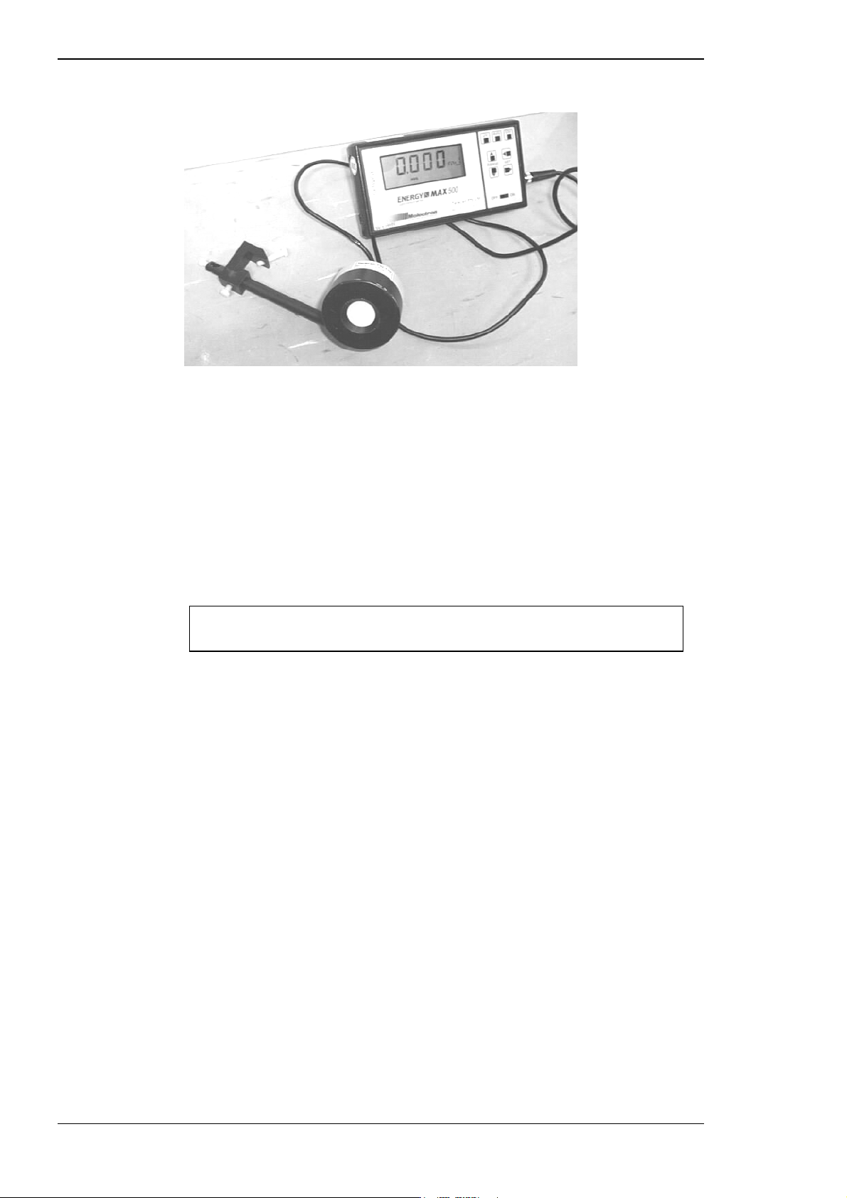
Alignment and calibration
Figure 6–1 Energy meter
Before calibrating the energy monitor, record the following information on
the calibration form:
⇒ date
⇒ name of person performing the calibration
⇒ Laserex Tango, Ultra Q or Solo serial number
⇒ energy meter type
⇒ energy meter calibration status
Record this information only for the final calibration, after optical
alignment has been completed.
Measuring YAG energy (Tango/Ultra Q)
Before beginning the full calibration procedure the system must be aligned
and functioning correctly. If the system is functioning normally, use the
following steps to check the calibration accuracy and proceed to full
calibration if required.
Verify the system is giving predicted energy levels within 30% of the actual
energy when the ENERGY control is rotated. If not, refer to Section 6.5.1.
If the displayed energy of test shots or treatment shots has a large error
(more than 50%) a voltage test should be carried out before calibration as
described in Section 10.7).
6-6 Tango, Ultra Q and Solo Service Manual
Issue 2.0
Page 89

Alignment and calibration
Procedure
To begin the calibration:
Turn the system on.
Select YAG treatment mode (Tango only)
Ensure the tower is rotated out of the way of the aiming beams.
Position the detector head of an appropriate energy meter about
60 mm in front of the objective lens in the laser head, and clamp
the detector head to the chinrest support.
Ensure the energy meter is calibrated for 1064 nm.
Adjust the position of the head of the energy meter so that both the
aiming beams are on the active area of the head and are
approximately 10 to 15 mm apart.
Determining optimal slit lamp position
Select READY status.
Select SINGLE PULSE mode.
Put Kodak burn paper in front of the detector head and fire the laser
at maximum energy, moving the slit lamp backwards and forwards
until the burn mark fills about 80% of the detector aperture.
Lock the slit lamp at this position and remove the burn paper.
Calibrating against the external meter
Turn the energy meter on and set the laser ENERGY control to
minimum.
Fire the laser several times and check that the external energy meter
reads between 0.25 and 0.35 mJ. (If it does not, the YAG energy
curve should be generated as described in Section 10.5.)
Set the energy meter scale to read a maximum of 55 mJ and set
laser energy to maximum.
Fire the laser at least three to four times, recording the results for
each shot for both the energy display reading and the external
energy meter reading.
Calculate the average for both groups of data, and compare.
If the energy display average is within ±15% of the external energy
meter average, no adjustment is necessary. If the difference
between the two readings is greater than ±15% run the voltage test
(see Section 10.7) then run the energy monitor calibration (see
Section 10.6).
Tango, Ultra Q and Solo Service Manual 6-7
Issue 2.0
Page 90

Alignment and calibration
Verifying system calibration
To verify the system calibration:
Turn the instrument off.
Wait ten seconds then turn it back on.
Check that no error occurs after initialisation/self test.
Fire the laser ten times at various laser energy settings, recording the
display and external energies on the Calibration verification record
(see Appendix E).
Ensure all readings are within 15% of each other at each setting and
that external and internal display energy readings are within 15% of
each other at each setting. If they are not, re-calibrate until
satisfactory.
If re-calibration has been required, complete another copy of the
calibration record sheet and retain for future reference.
Measuring SLT energy (Tango/Solo)
Before beginning the full calibration procedure the system must be aligned
and functioning correctly. If the system is functioning normally, use the
following steps to check the calibration accuracy and proceed to full
calibration if required.
Verify the system is giving predicted energy levels within 30% of the actual
energy when the ENERGY control is rotated. If not, refer to Section 6.5.1.
If the displayed energy of test shots or treatment shots has a large error
(more than 50%) a voltage test should be carried out before calibration as
described in Section 10.7.
6-8 Tango, Ultra Q and Solo Service Manual
Issue 2.0
Page 91

Alignment and calibration
To check the calibration:
Turn the system on.
Select SLT treatment mode.
Position the detector head of an appropriate energy meter about
200 mm in front of the objective lens in the laser head, and clamp
the detector head to the chinrest support.
Ensure the energy meter is calibrated for 532 nm.
Adjust the position of the head of the energy meter so that the
aiming beam is on the active area of the head and is approximately
centred.
Select READY status.
Fix Kodak burn paper in front of the detector head and fire the laser
at maximum energy, moving the slit lamp backwards and forwards
until the burn mark fills about 80% of the detector aperture.
Lock the slit lamp at this position and remove the burn paper.
Turn the energy meter on and set the laser ENERGY control to
minimum.
Fire the laser several times and check that the external energy meter
reads between 0.25 and 0.35 mJ. (If it does not, the SLT energy
curve should be generated as described in Section 10.5.2.)
Set the energy meter scale to read a maximum of 3 mJ and set laser
energy to maximum.
Fire the laser at least three or four times, recording the results for
each shot for both the control panel energy display reading and the
external energy meter reading.
Calculate the average for both groups of data, and compare.
If the energy display average is within ±15% of the external energy
meter average, no adjustment is necessary. If the difference
between the two readings is greater than ±15% run the voltage test
(see Section 10.7) then run the energy monitor calibration (see
Section 10.6).
Tango, Ultra Q and Solo Service Manual 6-9
Issue 2.0
Page 92

Alignment and calibration
Verifying system calibration
To verify the system calibration for the SLT treatment beam :
Turn the instrument off.
Wait ten seconds then turn it back on.
Check that no error occurs after initialisation/self test.
Select SLT mode.
Fire the laser ten times at various laser energy settings, recording the
control panel display and external energies on the Calibration
Record Sheet (see Appendix E).
Ensure all readings are within 15% of each other at each setting and
that external and internal display energy readings are within 15% of
each other at each setting. If they are not, re-calibrate until
satisfactory.
If re-calibration has been required, complete another copy of the
calibration record sheet and retain for future reference.
6.5 SETTING UP THE ATTENUATOR
The attenuator is calibrated by running the energy curve tests described in
Section 10.5.
6.5.1 Adjusting the energy prediction
The energy prediction is the value displayed while the ENERGY control is
being rotated. When it stops moving the system test fires and displays the
actual energy. If the actual energy is more than double or less than half of
the predicted value, a warning message is displayed to indicate the energy
calibration of the prediction could be in error and should be checked.
To make this adjustment for the YAG treatment beam (Tango/Ultra Q):
Turn the system on.
Select the YAG mode (Tango only)
Select SINGLE PULSE.
Turn the ENERGY control to maximum energy and note the
predicted energy displayed.
Check that the actual measured energy displayed after the test shot
is within ±30% of the predicted energy.
Repeat this procedure at several energy settings ranging from the
minimum to maximum settings.
If the energy prediction is within ±30% in the Tango, repeat the
procedure with the SLT treatment laser selected; if within ±30% in
the Ultra Q, skip to the section Checking the actual energy — YAG
optical pathway (see below); if out by more than 30%, skip to the
section If the energy prediction is out by >
6-10 Tango, Ultra Q and Solo Service Manual
Issue 2.0
±
30%…, below.
Page 93

Alignment and calibration
To make this adjustment for the SLT treatment beam (Tango/Solo):
Turn the system on.
Select the SLT mode (Tango only)
Turn the ENERGY control to maximum energy and note the
predicted energy displayed.
Check that the actual measured energy displayed after the test shot
is within ±30% of the predicted energy.
Repeat this procedure at several energy settings ranging from the
minimum to maximum settings.
If the energy prediction is within ±30% in the Solo, skip to the
section Checking the actual energy — SLT optical pathway
(Tango/Solo); if not see below.
If both YAG and SLT are within ±30% in the Tango) skip the section
below.
Caution
If the energy prediction is out by >
±
30%…
Run the voltage window test — see Section 10.7.
Run the appropriate energy curve test, as described in Section 10.5.
Re-check the energy prediction.
Checking the actual energy — YAG optical pathway
(Tango/Ultra Q)
Ensure the YAG treatment beam is selected (Tango only), then:
Position the detector head of an appropriate calibrated energy
meter in front of the Tango or Ultra Q in approximately the same
position as a patient's eye, and clamp the detector head to the
chinrest support.
Do not fire the laser yet as it may damage the detector.
Ensure the aiming spots cover approximately 80% of the detector
aperture.
Turn the external meter on and set it to read at 55 mJ.
Ensure the meter is calibrated for 1064 nm.
Turn the ENERGY control to maximum.
Set to READY status.
Fire the laser.
Confirm that the delivered energy display on the Tango/Ultra Q is
within ±15% of the external energy meter reading.
Repeat this procedure at several energy settings ranging from
minimum to maximum settings.
Tango, Ultra Q and Solo Service Manual 6-11
Issue 2.0
Page 94

Alignment and calibration
Analysing results
If the energy display is with ±15% of the external energy meter
reading, the energy monitor check is complete.
If the energy display is out by more than ±15%, run the voltage
window test (Section 10.7) then run the energy monitor calibration
— Section 10.6.
Checking the actual energy — SLT optical pathway (Tango/Solo)
Ensure SLT mode is selected (in the Tango), then:
Position the detector head of an appropriate calibrated energy
meter (see above) in front of the Tango or Solo and clamp the
detector head to the chinrest support. (Place in approximately the
same position as a patient's eye.)
Caution
Do not fire the laser yet as it may damage the detector.
Ensure the aiming spot covers approximately 80% of the detector
aperture.
Turn the external meter on and set it to read at 3 mJ.
Ensure the meter is calibrated for 532 nm.
Turn the ENERGY control to maximum.
Set to READY status.
Fire the laser.
Confirm the delivered energy display on the LCD is within ±15% of
the external energy meter reading.
Repeat this procedure at several energy settings ranging from
minimum to maximum settings.
If the energy display is with ±15% of the external energy meter
reading, the energy monitor check is complete.
If the energy display is out by more than ±15%, run the voltage
window test (Section 10.7) then run the energy monitor calibration
— Section 10.6.
6-12 Tango, Ultra Q and Solo Service Manual
Issue 2.0
Page 95

Alignment and calibration
6.6 CHECKING AIMING ACCURACY
The aiming beams pass through the same delivery system as the treatment
beam (both treatment beams in the Tango) and is coaxial with it. They
provide a good method of checking the integrity of the delivery system. If
the aiming beam spot is not present at the distal end of the delivery system,
or if its intensity is reduced or it looks diffused, the delivery system may not
be working properly or the aiming laser may be damaged.
It is critical to ensure the laser’s aim is accurate by following the procedure
described below at least every three months, or more frequently as
considered necessary by the operator.
The aiming accuracy should always be checked during any service visit.
6.6.1 Checking YAG aiming accuracy (Tango/Ultra Q)
This check ensures the YAG treatment beam coincides with the YAG
aiming beams. To check the aiming accuracy:
Turn on the system.
Select YAG mode (Tango only).
Attach (with double-sided tape) a piece of photographic burn paper
to the alignment target.
Mount the target on the chinrest so it is vertical, as shown in
Figure 6–2.
The alignment target is supplied with the system, and is usually kept in the
accessories drawer.
Turn on the system to illuminate the burn paper target.
Adjust the eyepieces to suit your eyesight.
The eyepieces are adjustable and can be pushed back to accommodate
spectacles.
Adjust the slit lamp to obtain full circle illumination and low
intensity.
Swing the illumination tower to one side (approximately 45°).
View the aiming beams through the binoculars and confirm that
they converge to form one spot on the paper attached to the target
as shown in section (c) of Figure 6–3.
If they do not, move the slit lamp.
Lock the slit lamp in this position.
Tango, Ultra Q and Solo Service Manual 6-13
Issue 2.0
Page 96
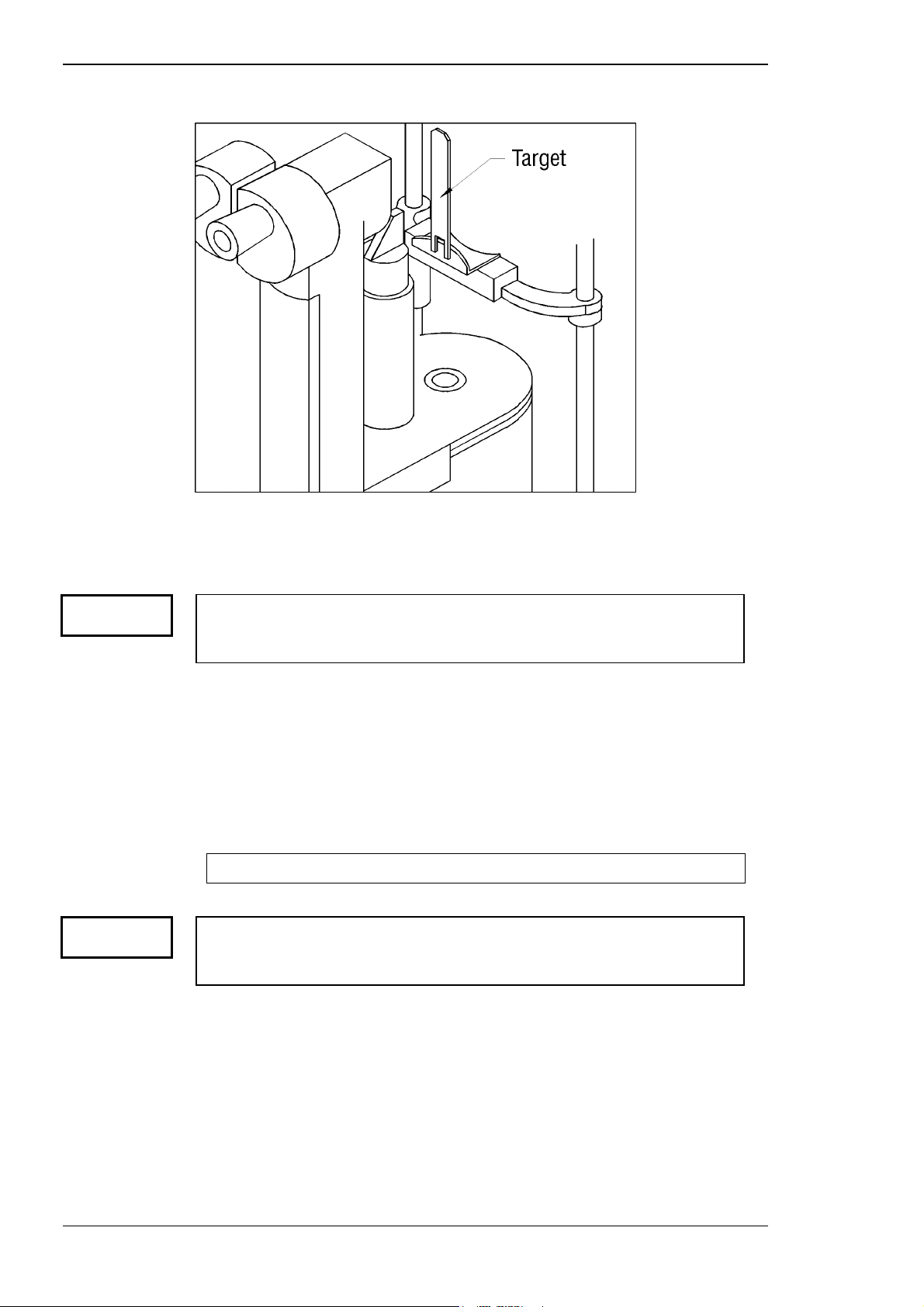
Alignment and calibration
Figure 6–2 Alignment target in position
(This diagram is intended to be a guide only.)
Caution
Caution
If the aiming beams do not converge as shown, continue with the optical
alignment.
If the aiming beams cannot be made to coincide, the system must not be
used on patients. Re-align the instrument, or return it to the factory for realignment
When the beams are converged, select READY status.
Select minimum energy.
Check that the aiming beams are still converged to one spot.
Fire the laser once onto the burn paper.
Inspect the burn mark through the binoculars to verify that it is
coincident with the aiming beam spot. See part (d) of Figure 6–3.
The test can be repeated if necessary on another area of the burn paper.
If the aiming beam is not centred in the burn mark, the system must be realigned and calibrated or returned to the factory for re-alignment and
calibration.
Leave the photographic burn paper in position on the alignment target for
the SLT aiming accuracy check (Tango only).
6-14 Tango, Ultra Q and Solo Service Manual
Issue 2.0
Page 97
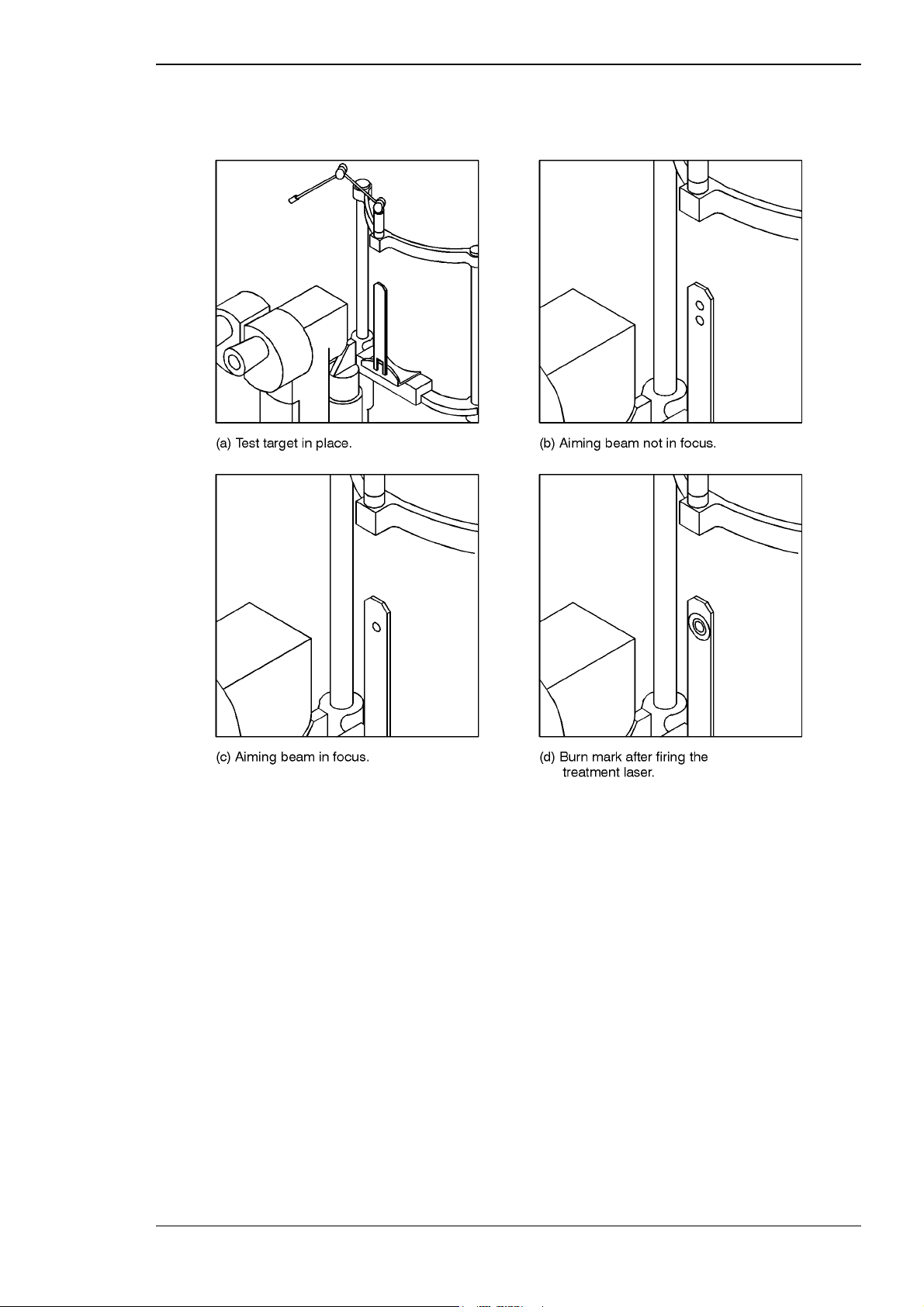
Alignment and calibration
Figure 6–3 Checking aiming accuracy
(This diagram is intended to be a guide only.)
Tango, Ultra Q and Solo Service Manual 6-15
Issue 2.0
Page 98
Alignment and calibration
6.6.2 Checking SLT aiming accuracy (Tango/Solo)
This check ensures the SLT treatment and aiming beams are coincident. To
check the aiming accuracy, with burn paper already attached to the
mounted target:
Turn on the system to illuminate the burn paper target.
Select the SLT treatment beam (Tango only).
Adjust the slit lamp (if necessary) to obtain full circle illumination
and low intensity.
View the aiming beam through the binoculars and confirm it is
directly over the YAG burn produced during the previous
procedure (Tango), or in the centre of the burn paper (Solo).
Lock the slit lamp in this position.
Caution
Caution
If the aiming beam is not visible, the system must not be used on patients.
Re-align the instrument, or return it to the factory for re-alignment
Select READY status.
Select minimum energy.
Check that the aiming beam is still centred over the YAG burn.
Fire the laser once onto the burn paper.
Inspect the burn mark through the binoculars to verify that it is
coincident with the aiming beam spot (and the YAG burn in the
Tango. See part (d) of Figure 6–3.
The test can be repeated if necessary on another area of the burn paper.
If the aiming beam is not centred in the burn mark, the system must be
realigned and calibrated or returned to the factory for realignment and
calibration.
6.7 ALIGNING THE YAG TREATMENT BEAM
(TANGO/ULTRA Q)
YAG treatment beam alignment is carried out in the following sequence:
⇒
adjusting the posterior YAG offset
⇒
aligning the aiming beams
⇒
adjusting DAM polarisation
⇒
aligning the viewing optics
⇒
running the YAG voltage window test
⇒
checking final calibration
⇒
checking air breakdown
6-16 Tango, Ultra Q and Solo Service Manual
Issue 2.0
Page 99

Alignment and calibration
6.7.1 Adjusting the posterior YAG offset
The following procedure sets the posterior offset.
Attach the posterior offset alignment jig to the top of the slit lamp.
Place a piece of matt black electrical tape on the metal target plate,
and place this on the magnetic target area of the jig.
Direct a desk lamp or torch at the target.
Turn on the system.
Set the slit lamp and aiming beam intensities to minimum.
Adjust the slit width to remove the slit illumination.
A magnification changer may be used to view the burn spots, if
required.
Move the Z adjustment of the jig to mid-position.
Bring the aiming beams together exactly by further turning the Z
adjustment.
Move the Z adjustment clockwise by 12.5 divisions on the dial.
The target will now be set at 250 µm posterior. Note that the dial
has 20 µm per division.
Set the energy to minimum, single pulse (0.2 or 0.3 mJ) and set the
posterior offset of the laser to the +150 position.
Adjusting burn spot size
Repeatedly fire the laser (slightly moving the target to the side after
each laser fire, and adjusting the starwheel on the BET) to obtain the
smallest possible burn spot on the target (see Figure 6–3 and
Table 6–1).
Always re-lock the focus locking screw of the BET after an
adjustment is made.
Once the starwheel position is correct, select a clear area of the
target and bring the aiming beams exactly together using the Z
adjustment.
Set the posterior offset to the MIN position.
Refer to Table 6–1 during the following procedures.
Tango, Ultra Q and Solo Service Manual 6-17
Issue 2.0
Page 100

Alignment and calibration
Setting posterior offset at 100 µm
At the 100 µm adjustment position:
Turn the Z adjustment by five divisions clockwise (which moves the
target 100 µm posterior), slightly move the target to a clear area
and fire the laser.
Set the posterior offset to +150 and slightly move the target, aiming
below the previous burn spot, then fire the laser.
Set the posterior offset to +250 and aim below the previous burn
spot, then fire the laser.
Setting posterior offset at 250 µm
At the 250 µm adjustment position:
Turn the Z adjustment by 7.5 divisions clockwise (which moves the
target 150 µm posterior).
Set the posterior offset to MIN and slightly move the target, aiming
to the left side of the first burn spot of the previous step, then fire
the laser.
Set the posterior offset to +150 and slightly move the target, aiming
below the previous burn spot, then fire the laser.
Set the posterior offset to +250 and aim below the previous burn
spot, then fire the laser.
Setting posterior offset at 350 µm
At the 350 µm adjustment position:
Turn the Z adjustment by five divisions clockwise, slightly move the
target to a clear area and fire the laser.
Adjust the target position in this and the following two steps so the
laser burn spots follow the pattern shown in the following table.
Set the posterior offset to +150 and slightly move the target, aiming
below the previous burn spot, then fire the laser.
Set the posterior offset to +250 and aim below the previous burn
spot, then fire the laser.
6-18 Tango, Ultra Q and Solo Service Manual
Issue 2.0
 Loading...