

HogNose
Building instructions.
March 19, 2018
Version 1.1
lasercutplanes.co.uk

THANKYOU FOR PURCHASING THE HOGNOSE FROM
"LASERCUTPLANES.CO.UK"
PLEASE READ THE MANUAL BEFORE STARTING TO FAMILIARISE
YOURSELF WITH THE BUILD PROCEDURE.
1:-The kit is supplied in 6 laser cut sheets. Sheets 1 to 5 are 1/16th
balsa. Sheet 6 is 1mm ply. There is also a bag of accessories
containing push rods, undercarriage wire, wheels etc.
2:- The items are held in place on the sheets by small tabs. These tabs
need to be cut through carefully in order to remove the items. Also due
to the varying density of the balsa there may be the odd place that the
laser has not cut fully through and any areas like this also need to be
cut through. A scalpel with a no11 blade is ideal for this.
3:- We find it best to leave the items on the sheets until they are
needed for the build. This way any small items are less likely to get lost
.
4:- The instructions which follow assume you are using the motor,
gearbox and receiver which can be bought as optional extras to the kit.
If you are NOT using these items then certain modifications will need to
be made to facilitate the fitting of any alternative parts.
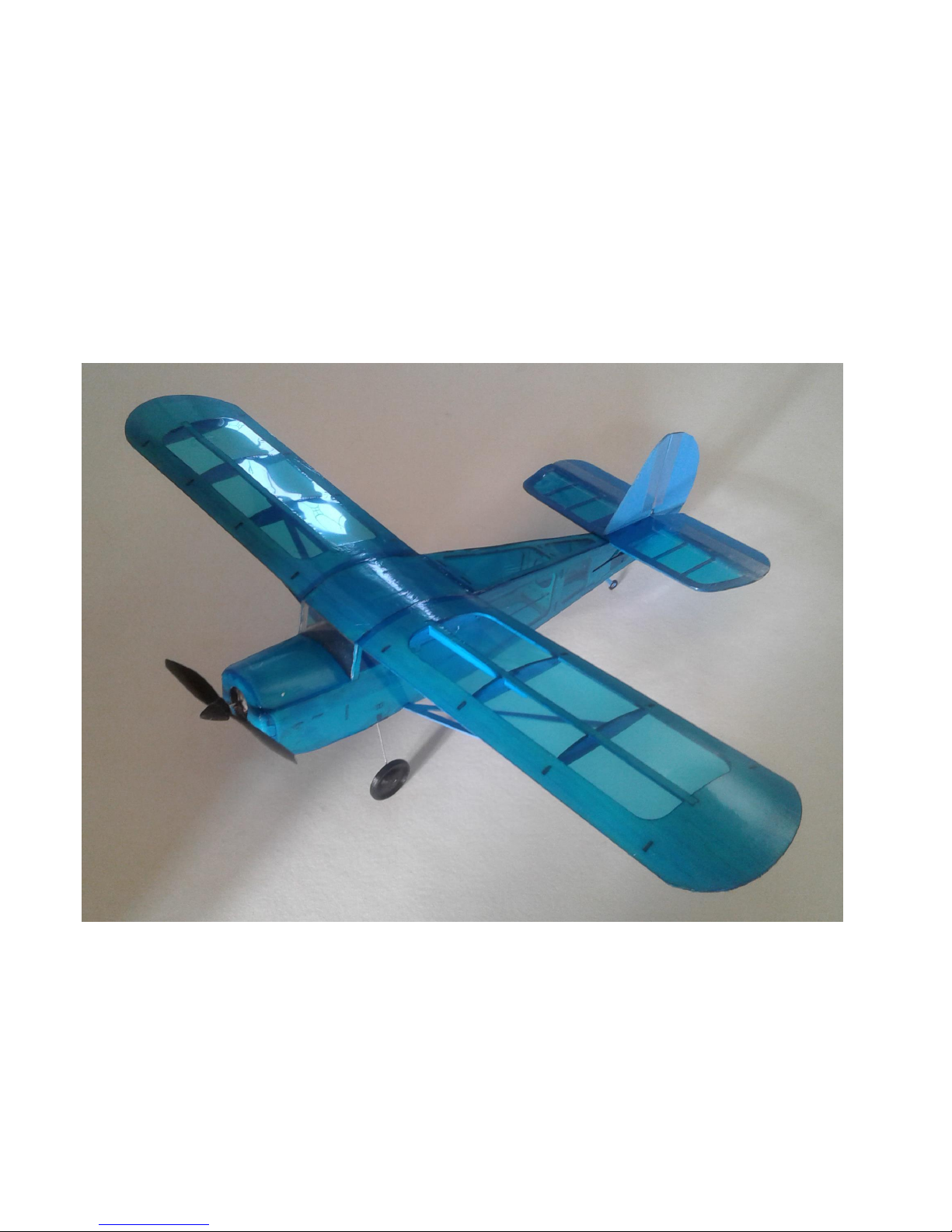
5:- The plane is designed for indoor flying or for outdoor in flat calm
conditions.
Specification.
Wing span = 490mm
Overall length = 400mm
Flying weight, (Including battery) = < 58 grms.
General Comments.
Please read before starting.
March 19, 2018
Version 1.1

WARRANTY
Lasercutplanes guarantee this kit to be free from defects in both material and workmanship at the
date of purchase. This warranty does not cover any component parts damaged by use or modification.
In no case shall Lasercutplanes liability exceed the original cost of the purchased kit. Further,
Lasercutplanes reserves the right to change or modify this warranty without notice.
LIABILITY RELEASE
In that Lasercutplanes has no control over the final assembly or material used for final assembly,
no liability shall be assumed nor accepted for any damage resulting from use by the user. By the act of
using the user-assembled product, the user accepts all resulting liability.
If the buyer is not prepared to accept the liability associated with the use of this product, the buyer is
advised to return this kit immediately in new and unused condition when a full refund minus postage costs will be
given.
THIS PRODUCT IS NOT SUITABLE FOR CHILDREN 12 YEARS OF AGE OR YOUNGER.
WARNING: The use of CA glue is advised for the kit assembly. Adhere strictly to the health and safety procedures
recommended by the manufacturers of the glue being used.
PRODUCT SUPPORT
This product has been engineered to function properly and perform as advertised, with the suggested
power system and supporting electronics as outlined within this product manual. Product support
cannot be provided, nor can Lasercutplanes assist in determining the suitability or use of
electronics, hardware, or power systems not explicitly recommended by Lasercutplanes.
For product assembly support, replacement parts, hardware, and electronics to complete this model,
please contact info@Lasercutplanes.co.uk
Lasercutplanes
Contact :- Info@lasercutplanes.co.uk
Sales :- sales@lasercutplanes.co.uk

Suggested Items needed to Complete this Model
Many of the suggested items listed below are available at your local hobby shop. For your convenience,
lasercutplanes stock most the power system components and some of the building supplies required
to complete this kit. If you have difficulties sourcing any of these items locally, please visit our website,
lasercutplanes.co.uk to purchase the items necessary to complete your model.
Suggested Electronics
☐ RC transmitter DSM2/DSMX with at least 3 channels
☐ Receiver/ESC/Servo brick (AR6410 or equivalent)
☐ Motor/Gearbox (PKZ3624)
☐ Propeller, 130mm x 70mm (EFL9051)
☐ LiPo battery, 120 - 160 mAh 3.7V
This assumes the use of Spektrum electronics. Other systems may be used.
Covering Film Requirements
Any high-quality covering film may be used to finish this model, superior results will be achieved by
using the lightest covering film possible. (Solite currently available to purchase with the kit).
☐ 1 - Pack of Solite sufficient to cover complete plane
Available in Transparent Red, Blue and Green. (other colours available to order).
We recommend the use of Acrylic paint to finish the bare wood parts of the model. This may be either brushed or
airbrushed on.
Required Building Supplies and Tools
☐ CA glue, medium,
☐ CA glue, thin,
☐ CA glue accelerator
☐ Hobby knife with supply of #11 blades
☐ Sanding block with 400 and 600 grit paper
Building Supplies and Tools
☐ Covering iron and heat gun
☐ Needle nose pliers, small
☐ Clear tape, 1/2 in.
☐ Velcro for mounting battery
☐ Masking tape
☐ Solite covering film
Optional Building Supplies and Tools
☐ Balsa filler (HCAR3401)
☐ Modeling clay (ballast)
☐ CA glue de-bonder (PAAPT16)
☐ Required Building Supplies
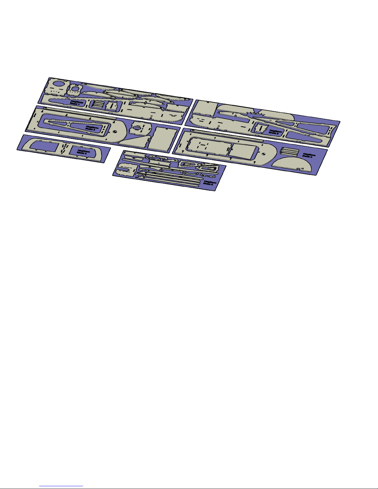
KIT INVENTORY.
5 X 1/16th BALSA SHEETS OF LASERCUT PARTS.
1 X 1mm PLYWOOD SHEET OF LASERCUT PARTS.
NOSE CONE IN 2 PARTS IN 1/8th BALSA.
2 X CARBON FIBRE PUSHRODS.
4 X PUSH ROD ENDS.
HEAT SHRINK TUBING.
PLASTIC RECEIVER CLIP.
PREFORMED UNDERCARRAIGE WIRE.
2 X WHEELS.
SUGGESTED OPTIONAL EXTRAS.
1 X AR6410 or EQUIVALENT, DSM2/DSMX 6 CHANNEL RECEIVER WITH LINEAR SERVOS AND
BRUSHED ESC.
1 X PARKZONE P51 MOTOR AND GEARBOX. (PKZ3624)
1 X E-Flite Micro 4-Site PROPELLER with SPINNER. (EFL9051)
1 X SOLITE COVERING FILM (TRANSPARENT BLUE, RED OR GREEN).
REQUIRED TO FINISH.
DSM2 OR DSMX COMPATIBLE TRANSMITTER.
LIPO BATTERY, SINGLE CELL 130-160 mAH
These suggestions are for Spektrum systems, When using other systems the electronic
requirements will, of course be different.
INVENTORY
March 19, 2018
HogNose building instructions
6
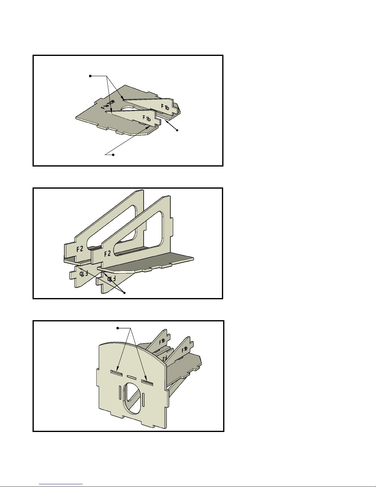
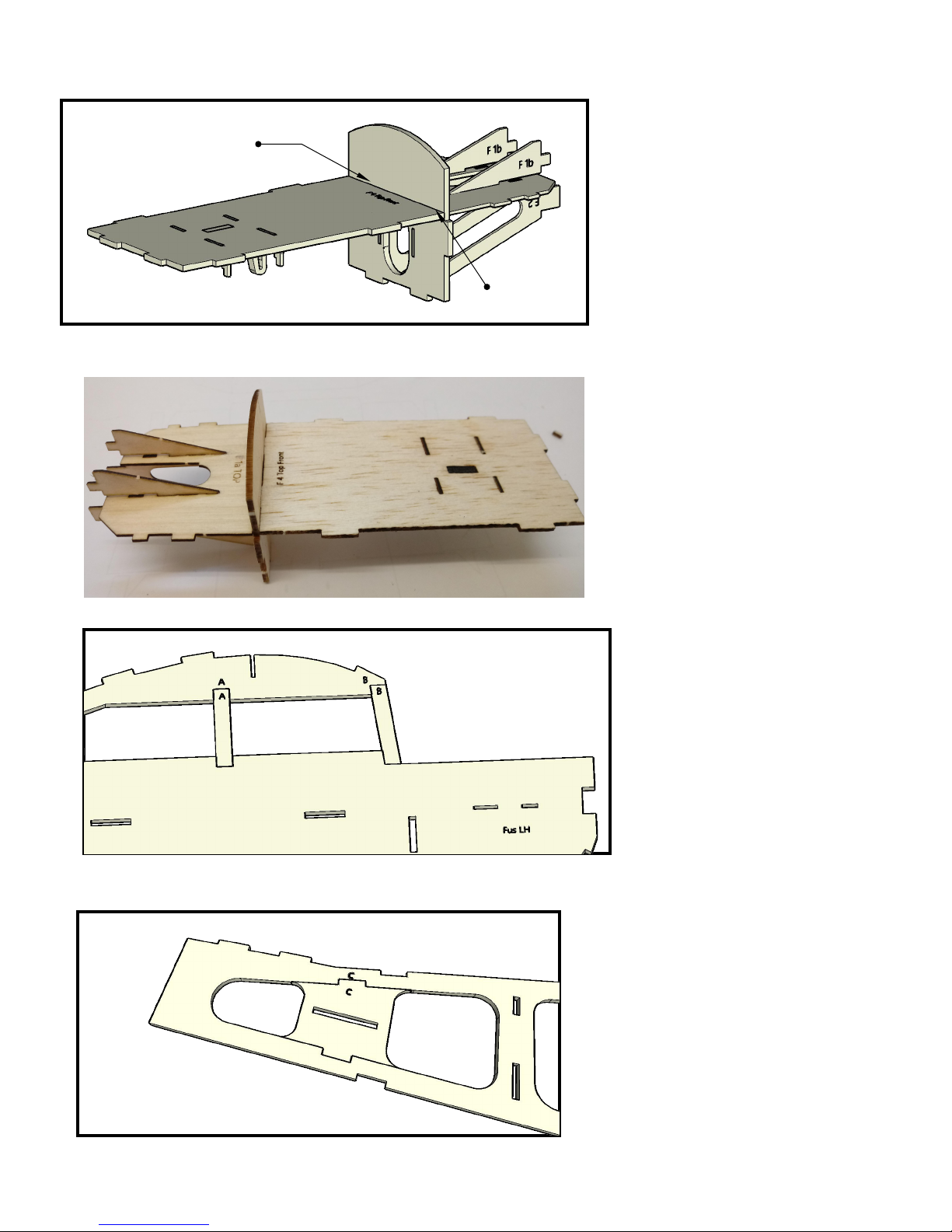
Step 1
Take item "F1a" (sheet 6) and place it on
a flat surface with the markings
uppermost.
Note that the recess for the motor is
intentionally angled to give the model
right thrust.
Glue the 2 items "F1b" (sheet 6) into the
slots in the TOP of "F1a" using 1 spot of
CA where shown.
Ensure no glue enters the slot at the front
of "F1a". This is where the motor will slide
into position.
Step 3
Step 2
Glue item "F3" (sheet 3) to the
back of the assembly made in
Step 1.
Note that 2 of the slots in "F3" are
left empty. These are used later.
1 spot of CA
Ensure no glue enters this slot.
Turn "F1a" over and glue the 2
items "F2" (sheet 6) into the slots in
"F1a"
Ensure no glue enters the slots
between "F1a" and "F1b".
No glue in these 2 slots
Motor
recess.
No glue in this slot
March 19, 2018
HogNose building instructions
7
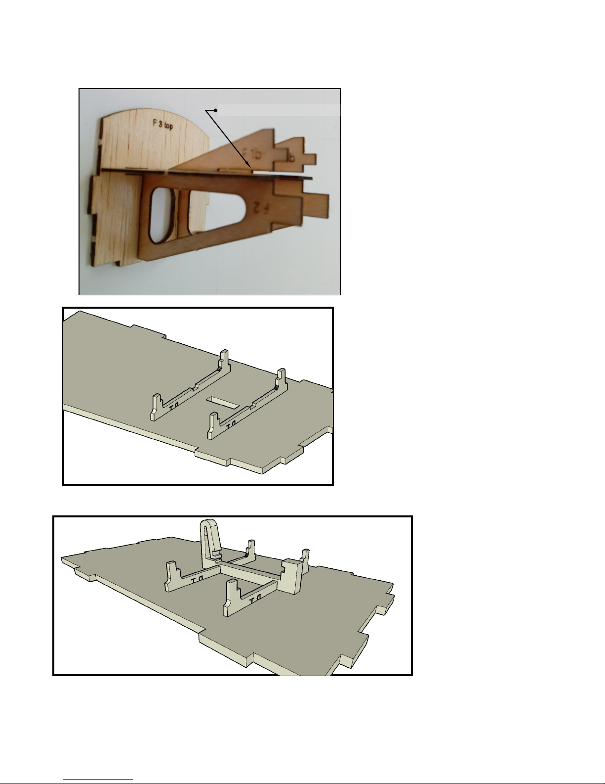
Step 5
Step 4
Locate the plastic receiver
clip (in bag of accessories)
and glue this into the slots
in "F4" and the 2 "RT's".
Photo of the completed assembly.
Note the slot for the motor is
completely clear. If this is not the case
use a small file or blade to clean it out.
Be careful not to enlarge it as the
motor mount needs to be a snug fit.
Set this assembly aside.
THIS STEP ONLY APPLIES IF YOU ARE
USING THE OPTIONAL RECEIVER SUPPLIED
WITH THE KIT. Otherwise you'll need a tray
to fit the receiver being used.
Take item "F4" (SHEET 4) and place it TOP
DOWN on the work surface.
Working on the UNDERSIDE:Locate the 2 plywood items "RT" (sheet 6).
Glue these into the slots provided in "F4".
Note they only fit one way around.
This slot must be clear
March 19, 2018
HogNose building instructions
8
This shows the completed
assembly.
Step 6
Step 8
Locate the small item "C" (sheet 1)
and glue this into place in the slots
provide at the rear of the fuselage
side. The slot in this item is for the
pushrod to pass through. (Elevator
or rudder).
Repeat this step on the RH Fus.
Keep all markings on the inside so
they don't show on the finished
model.
Photo of assembly.
Glue "F4" into the back of the
"F3" assembly from step 3,
ensuring a 90 degree joint
between the two. Ensure the top
of "F4" is uppermost.
(You can use one of the fuselage
sides to hold the items in the
correct position until the glue has
set but don't glue the assembly
to the fuselage yet).
Step 7
Glue
90 degrees
Take "Fus LH" and the items "A"
and "B" (sheet 1).
Glue "A" and "B" into their
corresponding positions in "Fus
LH".
Repeat this step on "Fus RH".
Keep all markings to one side.
That way they don't show on the
finished model.
March 19, 2018
HogNose building instructions
9
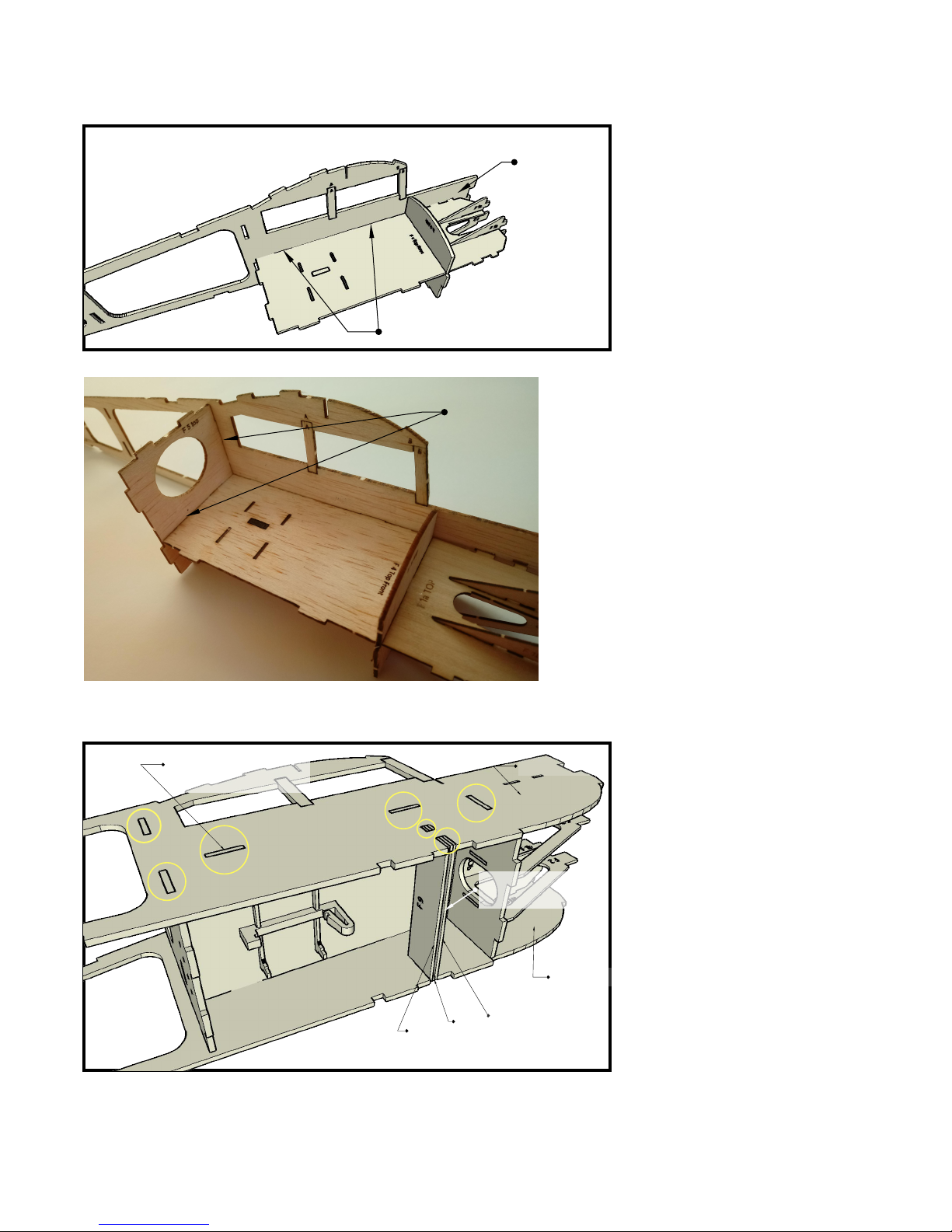
Step 9
FOLLOW THIS STEP CLOSELY.
Fit the "Fus RH" in place but DO
NOT GLUE.
Manoeuver "F7" "F8" and "F9"
(sheet 6) into place. ("F8" is
sandwiched between "F7" and
"F9" to form the slot for the
undercarriage to fit into).
You need to let the RH fuselage
side move out to achieve this.
When everything is correctly
seated, apply glue to the 7 tenons
(shown circled) on BOTH
FUSELAGE SIDES to hold
everything in place.
DO NOT allow any glue to enter
the undercarriage slot.
Step 10
Step 11
Take the assembly completed in
"Step 6" and glue it into the slots
in the "LH Fus". Note that there
will be a gap forward of "F3",
DON'T Glue this yet.
DO NOT GLUE THE OTHER
FUSELAGE SIDE TO THIS
ASSEMBLY.
Fit and glue "F5" (sheet 1) to
the fuselage LH side and also
to rear of "F4".
Ensure the markings on "F5"
are facing forward.
gap
Glue Glue Fus LH
Fus RH
F7F8F9
Glue the tenons
only
Undercarriage
slot

March 19, 2018
HogNose building instructions
10
Step 12
Step 15
Manoeuver item "F12"
(sheet 3) into position and
when correctly seated glue
just the 4 places where
shown. (DON'T glue to the
fuselage sides yet).
Turn the fuselage over.
Manoeuver item F13 (sheet 2)
into place and when correctly
seated glue just the 4 places
shown. DON'T glue to the
fuselage sides yet.
Step 13
Ensure a tight fit then apply glue
to all joints around "F4".
You can now pinch together the
front of the fuselage sides until
they are tight along the edge of
"F1a" and then glue in place.
Step 14
Fit "F6" (sheet 1) into the slots
in fuselage sides and pinch the
tail ends together. DO NOT
GLUE.
Ensure the markings on "F6"
are facing forward.
Hold the tail together with a
small piece of masking tape or
similar.
Glue Pinch and glue
Hold together with tape
F6
Glue Glue
F12
F13

March 19, 2018
HogNose building instructions
11
Remove the tape that was
holding the tail together and
check for perfect alignment.
This is very important because
if these are misaligned the
horizontal stabiliser will not fit
correctly.
When perfectly aligned, glue
the tail ends of the fuselage
together.
Step 18
The fuselage sides can
now be glued to "F12"
and "F13". Start at the
position shown and work
your way back to the tail
ensuring a good fit all
along.
Fit item "F15" and glue in place.
ENSURE that the undercarriage slot
is free from obstruction. DON'T
allow glue to enter the slot.
Step 16
Photo of "F13" in place. Note
the sides not glued.
Step 17
Sides not glued
Just the tabs glued
Perfect Alignment
Glue
Start here
Ensure good fit all
along.
"F13"
"F12"
Start here
"F15"
Don't allow
glue in slot

March 19, 2018
HogNose building instructions
12
Fit "NC1" (nose cone one 1/8th
balsa).
Squeeze the fuselage sides in to
make a tight joint and glue into
place around the edges and
around the tenons.
Ensure no glue enters the motor
slot.
Step 19
Step 20
Fit "NC2" and glue into place.
(fit with the markings
innermost. Shown this way for
clarity).
Ensure a good tight fit between
"NC1 and "NC2".
Ensure no glue enters the
motor slot.
Locate "F14" (sheet 6). and glue
into place at the front of the
receiver bay.
DO NOT allow any glue to enter
the undercarriage slot.
Test fit "F19" (sheet 4) under
the nose. Adjust if required by
lightly sanding the ends.
When happy with the fit, glue it
into place.
Step 22
Step 21
Check the fit at each end
Tight joint
Glue No glue in slot
Glue
Tightly together and
glue
NO GLUE in this slot.
"F14"
Keep slot clear

March 19, 2018
HogNose building instructions
13
Fit "F20" (sheet 3) noting that it
only fits one way. The edges
only go half way across the
fuselage side thickness, leaving
a small step to accept the wings.
Glue into place FROM THE
INSIDE to avoid glue entering
the step for the wings.
Step 23
Sand the nose cone into a pleasing shape.
Also lightly sand the whole of the fuselage rounding off
all sharp corners and removing any glue residue.
This completes the fuselage.
Set aside.
Step 24
Fit "F19" (sheet 4) with its' front edge flush with
the front of the nose cone. There should be a
small gap at the back of "F19" to accept the
windscreen. (fitted later).
Don't worry if there is an overlap at the sides,
this will be sanded off later.
Glue into place.
NOTE:If you are going to paint the inside of the cockpit,
then this is best done now before the next step.
Step 25
Flush
Small gap
Don't get
glue in this corner
F20

March 19, 2018
HogNose building instructions
14
Take the 2 "W4" wing ribs (sheet
1) and position them as shown.
Position a "W4a" (sheet 6) on
each rib and align it with the
markings on the rib.
The bottom edges must be flush.
Glue into place.
This strengthens the ribs at this
point and creates small pockets
to accept the wing stays later.
Step 26
Step 29
Take "W2" (sheet 1) and fit it
in the slot labelled "W2" on the
underside of the wing. Ensure
the correct way around and
that the rear edge is flush with
the wing edge.
Also make sure the rib is at 90
degrees to the wing.
The rib markings go next to
the wing markings. IE "W2"
next to "W2".
Glue only at the point shown.
Bend the wing around "W2" to
engage the tenon at the
leading edge. Glue just the
tenon into place.
Repeat steps 28 and 29 on the
other wing.
Step 27
Place "W1 LH" (sheet 4) on the
work surface with the markings
uppermost.
Fit "W1a" (sheet 4) into the slots
and glue in place.
Repeat this step on "W1 RH".
(sheet 3)
Step 28
Glue Glue this point only
these edges
level.
Glue here
only.
Pocket for wing stay
W2

March 19, 2018
HogNose building instructions
15
Fit "W3" (sheet 1) and "W4" (from step
27) to the wing, engaging the rib tabs into
their respective wing slots.
Ensure that you use the correct "W4"
assembly (from Step 27) so that the
pockets are facing inwards. i.e. The
reinforcing strip is on the outside.
Step 30
Photo of finished wings.
Turn the wing over and set on a flat
surface.
Glue only the tenons as shown. This should
ensure that the wing is flat and not twisted.
Check again by sighting along the ribs.
When happy, glue all ribs fully in place.
Ensure NO GLUE enters the slots for the
wing spar shown in picture for Step 31.
Repeat Step 31 and 32 on the other wing.
This completes the wings.
Set them aside.
Step 31
Repeat steps 28 and 29 for
the fitting of "W5" (sheet 1)
at the outer end of the wing.
Sight along the wings to
check they are not twisted.
Repeat on the other wing.
Step 32
Pockets facing inward.
Slots for wing spar.
W3W4.
Glue Glue

March 19, 2018
HogNose building instructions
16
Locate the 2 items "E2" (sheet 2)
and item "E1" (sheet 6)
Fit them together as shown on a flat
surface, (all markings on underside).
Note that "E1" is slightly thinner
than "E2".
The front edge MUST be in a straight
line so set this against a straight
edge and glue "E1" into place.
Ensure no glue enters the slots for
the elevator control horn.
Set aside.
Step 33
Step 36
Locate items "SA" and "SB", 2
of each. (sheet 6). These are
the wings stays.
Fit each pair together as shown
on a flat surface, Glue the
joints.
Ensure a strong joint.
Set aside.
Locate "VS" and "R". vertical
stabiliser (sheet 3) and rudder.
(sheet 4)
Lightly sand and round off the
edges shown. The joining edges
should be left square.
Step 34
Locate "HS" (sheet 5), and the 4
ribs marked "D" and "E". (sheet 4).
Fit he ribs into "HS" as shown and
on a flat surface, glue into place.
Set aside.
Step 35
Round off
Round off
Square
Square
E2E2E1
This edge MUST be straight
No glue in slots

March 19, 2018
HogNose building instructions
17
Locate "E3" (sheet 6).
Take the elevator assembly from "Step 33" and
place it on a flat surface with the markings
uppermost, as shown.
Insert "E3" into the slot shown. i.e. the right
hand slot when viewing from the straight edge.
It should be at 90 degrees to the elevator and
the small hole should be approximately
vertically over the edge of the elevator.
Glue into place.
Step 37
The model now ready for covering/painting.
PAINTING
Paint the following areas.
The receiver bay under the fuselage which takes the
receiver and the battery.
The underside of both wings.
Both wing stays from "Step 35"
The wing spar "WS" sheet 4.
The rudder assembly from "Step 37". BOTH SIDE AT
THE SAME TIME TO AVOID WARPING.
The elevator assembly form "Step 38". BOTH SIDES AT
THE SAME TIME.
Item "TS", (tail skid), sheet 4.
The horizontal stabiliser assembly from "Step 33".
BOTH SIDES AT THE SAME TIME.
The vertical stabiliser. BOTH SIDES AT THE SAME.
The nose cone can either be painted or covered with
film.
Step 38
Locate "R2" (Sheet 6), and fit it into the slot in
the rudder. This MUST be fitted from the side
of the rudder marked "R", also it must be at 90
degrees to the rudder and positioned so that
the small hole is approximately vertically over
the rudder edge.
Glue into place.
Step 39
Keep the horizontal stabiliser, vertical stabiliser, elevator
and rudder flat until fully dry.

March 19, 2018
HogNose building instructions
18
The uncovered area is required to allow for
the installation of the push rods.
This area will be covered after the receiver
and pushrods have been installed and tested.
Cover the following items.
The roof of the cockpit is best covered after
the wings have been fitted. This way the
joint can be covered and it looks neater.
If using a transparent covering film, don't
remove the film that covers the side cockpit
windows.
If using a solid colour covering, the
openings may be cut out and clear acetate
sheet attached to form the windows.
Remove all covering from along the wing
joint.
Underside of covered fuselage
Covered fuselage
Don't cover, access
required for installing
pushrods.
Don't cover
until after
wings are
fitted
No covering
along wing joint.
Cover side windows
The top surface ONLY of both wings.
The top surface ONLY of the horizontal stabiliser.
The whole of the fuselage except for the cockpit
roof and the underside of "F13".
This Photo shows the covered horizontal
stabiliser. NOTE:- This is only covered on the
upper side.
Is this photo the stabiliser has just been test
fitted and it is not glued at this stage.
Upper surface only
is covered with
film.
COVERING

March 19, 2018
HogNose building instructions
19
Top rear of fuselage
Remove all covering from along the
horizontal stabiliser joint.
Remove the covering from the pushrod
slots on both sides of the fuselage.
Step 40.
Locate "WS" (sheet 6).
Remove the covering from the
slots just under the cockpit
roof. Feed "WS" through the
slots.
Ensure that "WS" is the
correct way up. I.E. the tips
are higher than the centre.
There are marks to position
"WS" centrally but if these
have been obscured by the
painting, measure each side
to get it exactly central.
Then turn the model over to
gain access to the joint
through the windscreen hole
and run glue along the joint
as shown.
Remove covering
from pushrod slots.
Both sides
Tenons for horizontal
stabiliser must be free
from covering
Remover covering
from these notches
Slit the covering
to allow undercarriage
to fit.
Remove the covering from the notches for
the wing stays.
Slit the covering to allow the undercarriage
wire to enter its slot.
Measure from fuselage
to tip of "WS" to get
both sides equal.
VERY
IMPORTANT.
"WS" MUST
BE CENTRAL
Glue along
this joint
Remove covering
from slots
Positioning marks

March 19, 2018
HogNose building instructions
20
Step 41
Photo of the fuselage with "WS" fitted.
PUSHRODS.
Locate the 2 lengths of carbon
fibre, the 2 SMALLER diameter
push rod ends and cut 2 x
10mm lengths of the heat
shrink tube.
(bag of accessories)
Photo.
Step 42
Put the heat shrink tube over the
one end of the carbon rod, insert
a push rod end into the heat
shrink tube as shown.
Using a heat gun shrink the tube
onto the carbon rod and the
metal push rod end.
Repeat with the other items to
make two push rods.
Secure the tube onto the rods
with a drop of CA glue.
Fit the two pushrods to the receiver
linear servos as shown using the centre
hole on esch servo tab.
Ensure that the push rod ends are fully
engaged, the last bend should be
pointing upward.
Step 43
Small diameter metal push rod end
Heat shrink tube
Carbon rod
Drop of CA
Centre hole
Pointing up
Elevator pushrod
Rudder pushrod

March 19, 2018
HogNose building instructions
21
Step 45
With the receiver still attached and the correct
way up:Feed the other ends of the rods through the holes
in "F5" and "F6" which are marked "E" for the
elevator rod and "R" for the rudder rod.
It's the outer 2 holes in "F5" and the upper 2 holes
in "F6". (This view is of the underside).
The other holes are not used but may help if
fitting your own receiver.
And finally out through the slots in the
fuselage sides through piece "C".
These rod have been pre-cut to length
and should not require further
trimming.
Now fit the receiver into the receiver
tray and check it is fully located in the
small notches in the plastic receiver
clip. (SEE BELOW).
Step 44
E R Slot in "C" fuselage side.
Elevator pushrod
Rudder pushrod
Nose
Fit the receiver
to this slot first
Gently push
until the receiver
clicks into position
Note:- Push rods not shown in
this view for clarity.
To fit the receiver into the receiver
tray.
Locate the "V7" lettering on the
receiver and engage this part of
the receiver into the rear notch of
the plastic receiver clip.
Then gently push the front of the
receiver down until it engages in
the front clip.
"V7"
Fitting the receiver into the tray.
Tail

March 19, 2018
HogNose building instructions
22
Fit the horizontal stabiliser to the top rear of the
fuselage, covered side uppermost, making sure
to engage the 4 tenons into their slots. MAKE
SURE the horizontal stabiliser is at 90 degrees to
the fuselage.
Turn the fuselage over and glue the stabiliser
into place.
IT IS VERY IMPORTANT that the stabiliser is at
90 degrees to the fuselage.
Step 46
Step 49
Remove the covering form the top
centre portion of the horizontal
stabiliser as shown.
Fit the vertical stabiliser, ensure that all 3
tenons are fully engaged into their slots and
glue this in place.
IT IS VERY IMPORTANT that the vertical
stabiliser is at 90 degrees to the horizontal
stabiliser.
Step 47
Test the setup at this point.
Bind the receiver to your transmitter.
Test the operation of both elevator and
rudder.
If everything is running smoothly continue
with next step.
Step 48
Uncovered
face of stabiliser
Glue along
this joint ,both
sides
Remove covering
Glue along
this joint
both sides

March 19, 2018
HogNose building instructions
23
Step 50.
Take 2 pieces of adhesive tape, 1 at 50 x
12mm and the other 20 x 12mm.
Attach them to the rudder as shown. i.e. to the
side that does NOT have the control horn
attached.
Then attach the rudder to the
vertical stabiliser leaving a small
gap (1mm approx.) between the
two.
The rudder should have
approximately 30 degrees of
movement side to side.
Take 2 pieces of adhesive tape
55 x 12mm.
Attach them as shown to the
TOP of the elevator, i.e. to the
side that does not have the
control horn attached.
Step 51
Adhesive tape
Then attach the elevator to the horizontal stabiliser leaving
a small gap (1mm approx.), between the two.
The elevator should have approximately 30 degrees of
movement up and down.
Adhesive tape
1mm parallel gap.
1mm parallel
gap.

March 19, 2018
HogNose building instructions
24
Step 52
Repeat the above procedure with the
rudder.
The rudder must be straight before
shrinking the tube. Use DIRECT HEAT
as a heat gun WILL damage the
covering.
Power up the transmitter and receiver
and check that both rudder and
elevator operate correctly.
If all is well, the underside of F13 can
now be covered with film.
Cut a short length, (approx. 15mm) of
the heat shrink tubing supplied. Slide
this over the end of the elevator
pushrod.
Take one of the larger diameter push
rod ends. Fit the "Z bend" to the
elevator control horn ensuring that it is
correctly seated with the end pointing
away from the elevator, then slide the
other end into the heat shrink tube.
Note that the end is bent to bring the
wire parallel to the pushrod. This bend
may need adjusting.
Position the elevator so it is IN LINE with
the horizontal stabiliser and then apply
heat to the tube to shrink it onto the
pushrod and end.
Use DIRECT HEAT for this because a
heat gun WILL damage the covering.
Make sure the end is held in place BUT
DON'T GLUE. This will be done after
trimming the aircraft.
Step 53
Heat shrink tube
Push rod end
Elevator control horn
Heat shrink tube
Push rod end
Rudder control horn
F13

March 19, 2018
HogNose building instructions
25
Cut a piece of covering film about 8mm
wider than the cockpit roof. Cover the
cockpit roof overlapping the joints with
the film.
Step 54
Step 57
With the model upside down, locate the
wing stays, ("SA + SB" step 35).
These MUST be fitted the correct way
around, with the longer arm "SB" to the rear
of the plane.
Fit the joined end into the slot in the
fuselage side and "SB" into the rear pocket
in "W4/W4a". Glue the stay in place at these
two points ONLY. (see photo).
Now bend the wing slightly to engage the
end of "SA" into its' pocket in "W4/W4a".
Glue this into place.
When you view the wing end on, it will be
twisted with its' front edge lower at the tip.
This is called "washout" and enables the
plane to fly slower without stalling.
Fit the stay on the other wing in the same
way.
Step 55
Take a wing and carefully slide it along
the wing spar until it meets the
fuselage side. The spar fits through the
slots in "W2" and "W3".
When a good fit is achieved glue all
areas shown.
Repeat with other wing.
Step 56
Glue along this joint
Glue along length
of spar.
Glue spar to ribs
Overlap this joint
with film
SBSAGlue
Glue
Manipulate wing to engage
here, then glue into place
SB
SA

March 19, 2018
HogNose building instructions
26
Fit the wheels onto the wire and
then shrink another short length
of tube outside the wheel.
Ensure that the wheels turn
freely, then trim off the excess
wire.
Step 58
Slit the covering (if not previously done) from
over the undercarriage slot and insert the
undercarriage wire.
Then fit "LG1" (Sheet 6), into the slot
...........
.... and push it right in so that
the it grips the undercarraige
wire fully.
Ensure that the undercarriage is
central.
Apply glue to the places shown
to secure the undercarriage into
position.
Carefully bend the wire if
necessary to get the plane level
when on its' wheels.
Step 59
Locate the undercarriage wire.
Cut 2 short lengths, (about
3mm long) of heat shrink tube
and shrink them onto the wire
as shown.
Step 60
Short length of tube
2nd piece of heat shrink tube
Trim the wire here
Slit the covering
Push "LG1" into the slot
Glue

March 19, 2018
HogNose building instructions
27
Fit the tail wheel, "TS" (sheet 6)
and glue into place making sure
its at 90 degrees to the fuselage.
Step 61
Step 63
Locate the acetate sheet
windscreen and fit it into the
slots in the fuselage side. Trim
it to size if necessary and then
glue into place.
Take the motor and gearbox and cut off the
4 spikes from the holder as shown.
Remove the covering from the
tail wheel slot on the underside
as shown.
Step 62
Remove covering
Glue
Slot
Glue Cut off 4 spikes

March 19, 2018
HogNose building instructions
28
Feed the motor power wires through the nose and
into the receiver bay.
Insert the motor and gearbox into the slots in the
nose cone as shown with the larger gear for the
propeller uppermost ..........
Step 64
........ then push it fully into the nose. The large
gear should be just inside the nose cone.
The motor is held in place by friction alone, if
however you find the motor isn't held tight
enough, it may be glued in place.
Hot glue or any wood glue is fine for this.
DON'T GET GLUE ON ANY OF THE MOVING
PARTS.
NOTE The motor and propeller shaft will not be in
line with the fuselage. they will be pointing
approximately 3 degrees to the right when
viewed from above.
This is required to compensate for the rotation of
the motor.
Step 65
Attach the propeller as it's
easier to do at this stage.
Step 66
UP
Carefully remove a logo from the
black vinyl sheet and fix it as shown to
the fuselage side.
Repeat on the other side of the
fuselage.

March 19, 2018
HogNose building instructions
29
Step 68
Connect the motor power wires
to the "esc" output of the
receiver.
There are 2 pins on the motor
plug but 3 sockets in the
receiver ESC.
The motor plug MUST be fitted
into the correct sockets and also
the correct way around in order
for the motor to work correctly
and in the correct rotation.
Fit the plug as shown in the
photo.
Attach a piece of "Velcro" to
the side of the receiver bay as
shown to support the battery.
Power up your transmitter and
the receiver and test that the
motor is working correctly in
the correct direction.
Step 67
Step 69
Velcro
Battery
FRONT
Glue the spinner onto the
propeller.
White wire
Black wire
No connection

March 19, 2018
HogNose building instructions
30
Congratulations the
plane is complete
and ready for flight
tests.
The plane is designed for indoor flying. (Can be flown outdoors in flat calm conditions).
Before flying the model, check that the rudder and elevator and in the neutral position. i.e. straight.
Check that the centre of gravity is correct by supporting the plane on two fingers resting on the C of G
spots on the underside of either wing.
Check that both rudder and elevator and operating in the correct direction. 20 degrees of movement in
each direction is usually enough.
As the plane does not have ailerons, you may prefer to set up a mix on your transmitter to make the
right stick control both elevation and direction. This is optional.
Test fly the plane and then manually adjust the rudder and elevator positions to give a straight and
level flight with "hands free" from the transmitter.
When happy with the flight, apply a spot of glue to the heat shrink tubing holding the rudder and
elevator push rod ends to secure them into position.
We hope you enjoy flying the HogNose.
If you have any comments regarding the HogNose or this instruction manual please email us at
:- Info@lasercutplanes.co.uk.
Complete
 Loading...