

Page 1
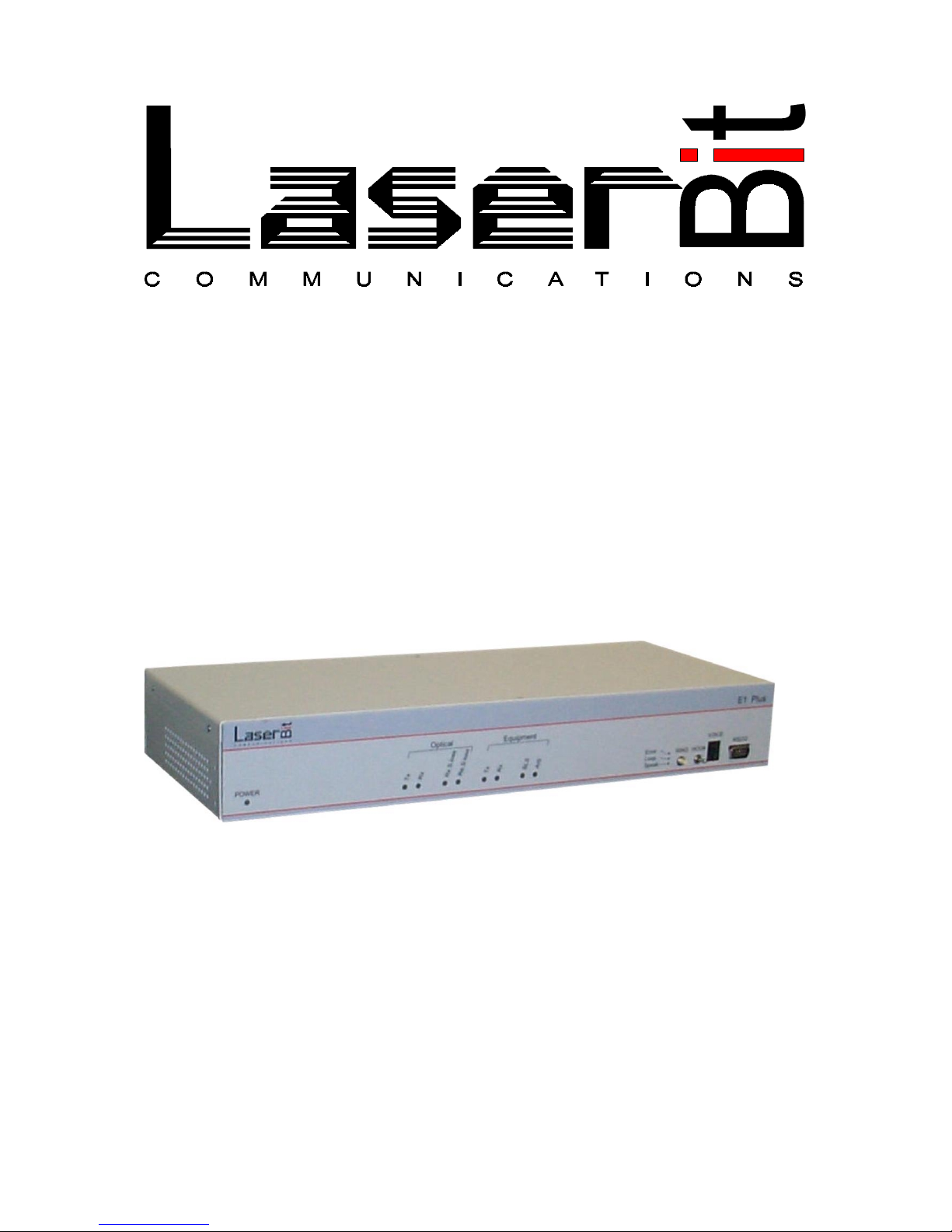
E1 Fiber Optic Converter
with Service Channel Interface
LE-820M/1E1 Plus
LE-1300S/1E1 Plus
User’s Manual
Rev. 2.0
LaserBit Communications Corp.
1037 Budapest,Kunigunda u. 45.
HUNGARY
Tel.: +36-1-4537440
Fax: +36-1-2403570
www.laserbitcommunications.com
Page 2

Copyright Statement
Copyright © 2000 LaserBit Communications Corp. All rights reserved.
No part of this documentation may be reproduced in any form or by any means or used to
make any derivative work (such as translation, transformation or adoption) without written
permission from LaserBit Communications Corp.
LaserBit Communications Corp. reserves the right to revise this documentation and to make
changes in content from time to time without obligation on the part of LaserBit
Communications Corp. to provide notification of such revision or change.
LaserBit Communications Corp. provides this documentation without warranty, term, or
condition of any kind, either implied or expressed, including but not limited to, the implied
warranties, terms of conditions of merchantability, satisfactory quality, and fitness for a
particular purpose. LaserBit Communications Corp. may make improvements or changes in
the product(s) described in this documentation at any time.
Trade Marks
LaserBit
is a registered trade mark of LaserBit Communications Corp. All other trademarks
belong to their respective owners.
Page 3

Limited Warranty
LaserBit Communications Corp. warrants that the LaserBit product purchased will free from
defects in material and workmanship for a period of one (1) year from the date of purchase.
This warranty period will not be extended by virtue of a repair of the product or a replacement
of any component of the product during the warranty period.
This warranty covers only normal commercial use. LaserBit Communications Corp. is not
responsible for warranty service should the LaserBit identification marks, serial numbers or
original seals be removed, altered, or broken, or should the product fail to be properly
maintained or fail to function properly as a result of any modification, misuse, abuse,
improper installation, neglect, improper shipping, damage caused by disasters such as fire,
flood, earthquake or lightning, improper electrical current, or service other than by LaserBit
Communications Corp. or its authorized partners.
If the LaserBit product fails to operate as warranted at any time during the warranty period,
LaserBit Communications Corp. will repair, or at its option, replace the defective product at
no additional charge.
In no event will LaserBit Communications Corp. be liable for any damages including loss of
data, lost profits, lost savings, lost business, or other incidental or consequential or indirect
damages arising out of the installation, use, maintenance, performance, failure or interruption
of the LaserBit product, even if LaserBit Communications Corp. has been advised of the
possibility of such damage.
If you purchased the LaserBit product in the United States, some states do not allow the
limitation or exclusion of liability for incidental or consequential damages, so the above
limitation may not apply to you.
The purchaser or user shall have the responsibility to give LaserBit Communications Corp.
prompt written notice of any warranty claims. If the product was purchased through an
authorized partner of LaserBit Communications Corp., notice may be given in writing to that
authorized partner in the area in which the product was being used.
The product may be returned to LaserBit Communications Corp. only if it has a Return
Material Authorization (RMA) number. The product must be shipped prepaid, insured and in
the original shipping package or similar package for safe shipment. The RMA number must
be marked on the outside of the shipping package. Any product returned without an RMA
number shall be rejected.
Transportation charges for the return of the product will be paid by LaserBit Communications
Corp. if it is determined by LaserBit Communications Corp. that the product was defective
within the terms of the warranty; otherwise the purchaser or user shall be responsible for costs
of return handling and transportation.
If the LaserBit product does not operate as warranted above, the customer’s sole remedy shall
be, at LaserBit Communications Corp.’s option, repair or replacement. The foregoing
warranties and remedies are exclusive and are in lieu of all other warranties, expressed or
implied, either in fact or by operation of law, statutory or otherwise, including warranties of
merchantability and fitness for a particular purpose. LaserBit Communications Corp. neither
assumes nor authorizes any other person to assume for it any other liability in connection with
the sale, installation, use or maintenance of the product.
Page 4

About This Guide
This manual provides all the information required to install, configure, and use
LE-820M/1E1 Plus and LE-1300S/1E1 Plus E1 to fiber optic converters. The
above two models are identical in their functionality with the only difference
being in their optical interface. While the LE-820M/1E1 Plus has multimode
optical interface operating at 820 nm wavelength, the LE-13001E1 Plus has
single mode fiber optic interface operating at 1300 nm wavelength. For the sake
of simplicity the naming convention “E1 Plus” will be used to cover both
models throughout this guide. The manual is intended for use by personnel
familiar with telecommunication networks; consequently it assumes basic
knowledge of telecom networks and ITU-T G.703 concepts.
Overview of the User’s Manual
Introduction – provides general information about the E1 Plus.
Installation – helps to understand and install the E1 Plus.
Configuration – explains all available settings on the E1 Plus and what options
exist for configuration and use.
Specifications – lists the equipment’s specifications.
Port pinouts – provides pinout data for the equipment’s ports.
Glossary – provides the meaning for some networking terms used in this manual
Page 5

Table of Contents
1. Introduction .......................................................................................................6
1.1 General Description......................................................................................... 6
1.2 Theory of operation .........................................................................................6
2. Installation .......................................................................................................13
3. Configuration...................................................................................................14
3.1 Location of connectors and indicators...........................................................14
3.2 E1 Plus unit internal module arrangement ....................................................15
3.3 Configuration Jumpers – E1SC-MM ............................................................15
3.4 Configuration Jumpers – E1SC-UIM............................................................18
3.5 Service channel configuration settings (S1, S2)............................................19
4. Technical specifications ..................................................................................21
5. Port Pinouts......................................................................................................23
6. LED Description..............................................................................................26
Appendix A – E1 Background ............................................................................28
Appendix B - Characteristics of the PDH system. ..............................................30
Appendix C - Summary of PDH transmission rates ...........................................31
Appendix D - GLOSSARY .................................................................................32
Page 6
1. Introduction
1.1 General Description
The E1 Plus fiber optic converter (LE-820M/1E1 Plus and LE-1300S/1E1 Plus)
products from LaserBit Communications offer cost effective and highly reliable
solution for connecting equipment with ITU-T G.703 (E1) interface to optical
networks. The converters give fully transparent connection both for structured or
unstructured signals at E1 (2.048 Mbps) level. The devices are designed to be
extremely flexible yet easy to use. The copper line interface is configurable both
for balanced (UTP) and unbalanced (COAX) connection. Copper and fiber loop
back modes provide useful help in troubleshooting. The loop back modes also
can be turned on and monitored remotely. Color LED indicators provide
extended status and alarm reporting. The selectable line coding and AIS
handling gives further flexibility when integrating the equipment into an existing
system. The E1 Plus models are equipped with Service Channel feature, which
transmits one voice channel, one RS-232 channel and 2 x 24 low speed signal
bits on top of the data stream. This solution makes the equipment ideal for
applications where alarm and status monitoring or remote management of other
equipment is required. Besides the AC Power Supply, the devices can be
ordered with 48 VDC PSU for Telco applications.
1.2 Theory of operation
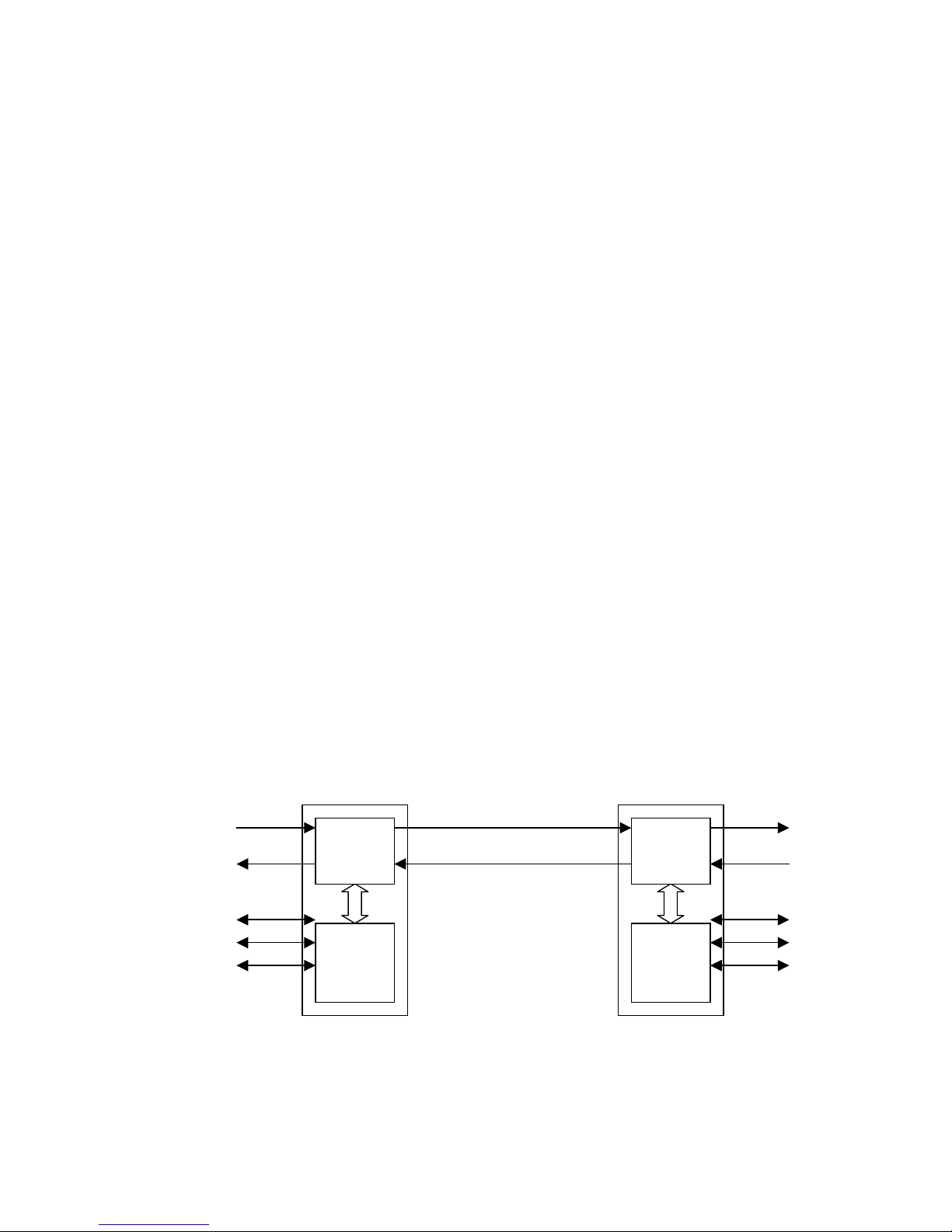
The basic function of the E1 Plus converter is to transmit and receive E1 signal
over fiber optic networks. In addition to that, the equipment is capable of
transmitting auxiliary service data on top of the standard E1 data stream. The
two functions are realized by two independent functional units inside the device
as it is shown on Figure 1 below.
A – RS-232 serial, duplex, up to 38.400 kbps
B – Analogue voice channel, 16 kbps ADPCM
–
E1
Fiber optic link
E1SC-MM
SC-UIM
E1SC-MM
SC-UIM
E1
A
B
C
A
B
C
Page 7
The E1SC-UIM (User Interface Module) gathers the RS-232 asynchronous
serial data, the analogue voice channel and the alarm and control signals
together and converts them into a synchronous 64 kb/s digital data stream using
unique framing and error correction protocol. This data is then passed to the
E1SC-MM (Media converter and Multiplexer) module, which multiplexes the
service channels and the incoming E1 data onto a 2.5 Mb/s digital stream then
converts it to optical signals. At the opposite side the optical signals are
converted back to electrical, de-multiplexed and the data is passed to the
corresponding interfaces, that is E1 to the line interface and service channels to
the SC-UIM module. The SC-UIM module decodes the 64 kb/s digital data and
converts it back to RS-232 serial, analogue voice and low speed signaling.
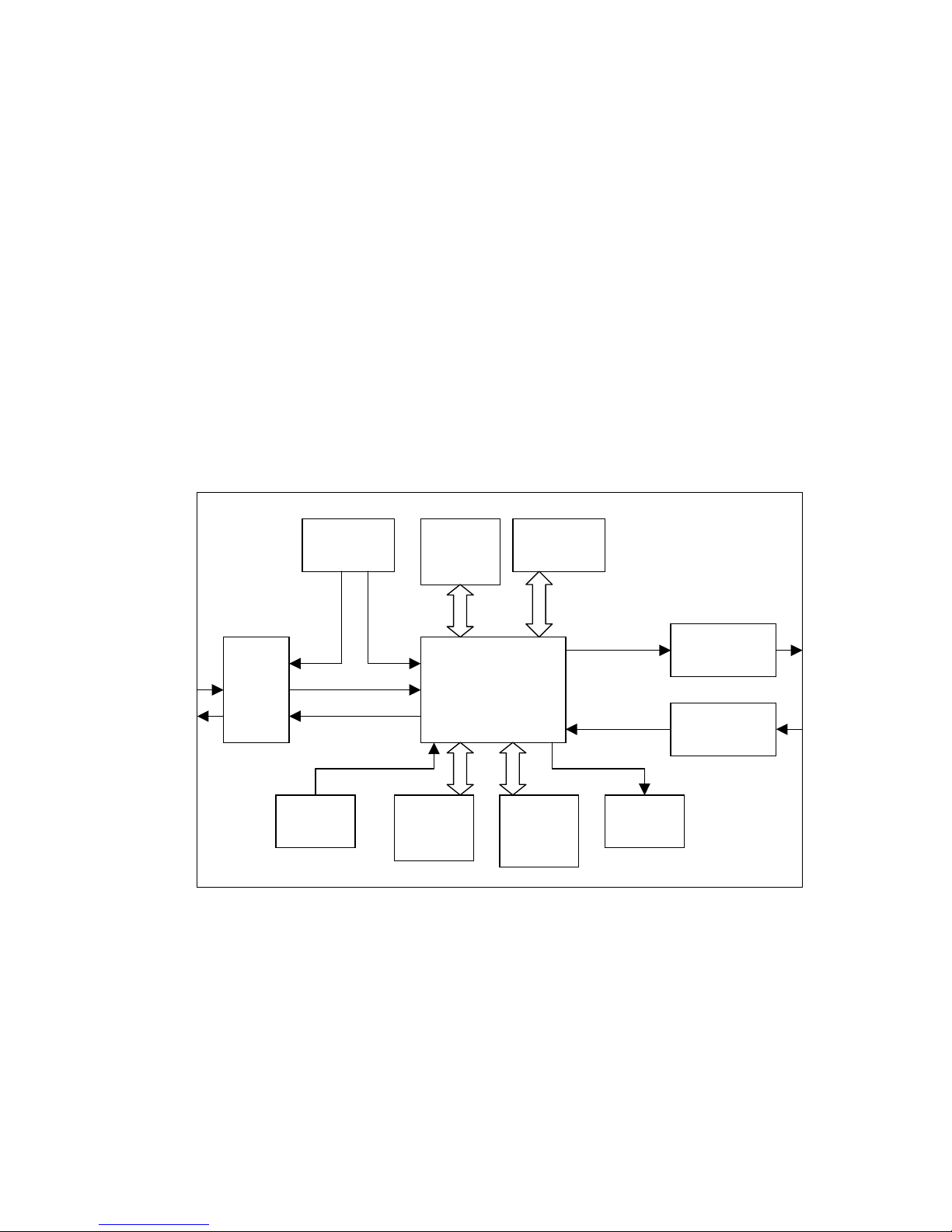
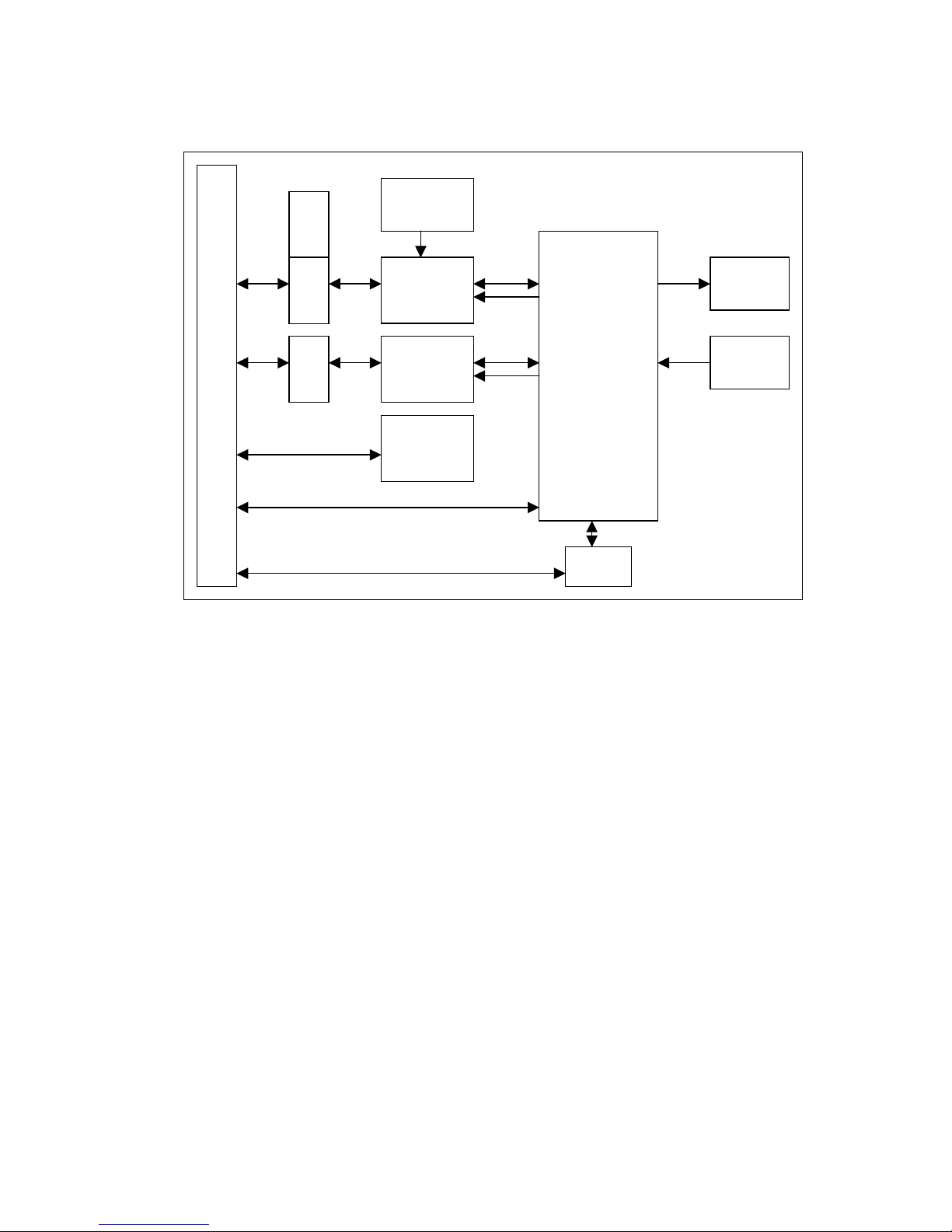
More detailed information about the functional blocks inside the individual
modules can be seen on Figure 2. (E1SC-MM) and Figure 3. (SC-UIM) E1SCMM (Media converter and Multiplexer).
Figure 2. E1SC-MM Function Blocks
E1 line interface
The E1 line interface provides physical connection to the E1 network via
balanced 120 Ohm UTP or unbalanced 75 Ohm coaxial ports. It provides data
and clock recovery, AMI/HDB3 encoding and decoding, AIS and BPV
detection.
Master
CLK
CPLD
logic
E1 line
interface
FO
transmitter
FO
receiver
PLL
circuits
SC-IF
J Tag
DIP
SW
Management
interface
Front
panel
Page 8

CPLD logic
The CPLD (Complex Programmable Logic Device) is the heart of the E1 Plus
unit. The two major functions of this block is to multiplex/demultiplex the E1
data and the service channel data and to perform the encoding and decoding of
the optical serial data.
PLL (Phase Locked Loop) circuits
Three independent PLL’s are used by the CPLD logic for the encoding and
decoding of the optical serial data.
FO transmitter/receiver
The fiber optics transmitter and receiver convert the electrical signals to optical
and the optical to electrical respectively.
Master Clock
The Master Clock is used as a reference clock source when the device looses the
sync on the E1 side. By doing so the service and management communication
between the two E1 Plus units is not affected by the sync loss.
SC-IF
The Service Channel Interface is the interconnection between E1SC-MM
(Media converter and Multiplexer) and the E1SC-UIM (User Interface Module).
It carries synchronous duplex 64 kbps data, which contains the RS-232
asynchronous serial data, the analogue voice channel and the alarm and control
signals.
DIP SW
The configuration switch block contains 8 micro switches used to select line
coding, E1 line loop back and fiber loop back.
J Tag
The J Tag is the test interface of the CPLD logic, through which the
functionality of the electronics can be checked. The same interface is used to
download the new operating code to re-program the CPLD.
Page 9

Management Interface
The management interface provides information about the local and remote
frame sync loss and can be used to set the device to dual loop back mode.
Front Panel
The Front Panel gives information about the actual status of the equipment
including power, optical and E1 line status.
Operation
The E1 line interface receives the G.703 data, recovers the clock from the signal,
decodes the data and detects AIS or BPV errors. The recovered clock and data
then passed to the CPLD logic. This programmable electronics receives the E1
data and clock and the service channel data, multiplexes them into a 2.5 Mbps
synchronous data stream. This data stream is then encoded for optical
transmission and passed to the FO transmitter, which converts the electrical
signals to optical. In the opposite direction the optical signal is received by the
FO receiver, converted to electrical and transmitted to the CPLD block. The
CPLD decodes the data stream, demultiplexes it and sends the E1 data and the
recovered clock to the E1 line interface. The service channel data is passed to
the service channel module. The E1 line interface module encodes the data
received from the CPLD block using AMI or HDB3 coding and transmits the E1
signal out to the G.703 port.
Page 10
E1SC-UIM (User Interface Module)
Figure 3. E1SC-UIM Function Blocks
CS1 System connector
All signals of the SC-UIM are available on this 96 pin connector. Two DB-37
connectors are used to make these signals accessible on the rear side of the unit.
CS2
DB-9 connector for RS-232 connection, situated on the front side of the
equipment.
CS3
RJ-11 connector for telephone handset connection, placed on the front side of
the equipment.
Serial remote control bus
CS1
S3
S4
CS3
CS2
Analogue
Audio
Channel
RS-232
Interface
Status and
Control
Bits
20.48 MHz
VCO
FPGA
logic
CS4
DIP
Switches
LED
Display
Page 11

CS4
The CS4 multiplexed digital data connector is a ten-pin interface provides
interconnection between E1SC-MM (Media converter and Multiplexer) and the
E1SC-UIM (User Interface Module). It carries synchronous duplex 64 kbps
data, which contains the RS-232 asynchronous serial data, the analogue voice
channel and the alarm and control signals.
S3
Analogue voice channel momentary push button. Pushing the button will cause
the buzzer of the remote unit to buzz until the button is released. This button is
used to warn the remote side to switch its S4 switch to “hook-on” position after
a conversation is finished.
S4
Analogue voice channel hook switch, used to initiate a voice call. The normal
position of the switch is “hook-on”. If it is switched to “hook-off” position, the
buzzer of the remote device start buzzing while the green status LED starts
blinking at both sides. After changing the position of the switch at the remote
side to “hook-off” the buzzer will stop and both LED’s change to steady green.
The voice communication channel is now open. The channel can be close by
turning any of the to S4 switches to “hook-on” position.
FPGA logic
The FPGA (Field Programmable Gate Array) is the central controlling and
processing unit of the service channel module. It gathers the RS-232
asynchronous serial data, the analogue voice channel and the alarm and control
signals together and converts them into a synchronous 64 kb/s digital data
stream using unique framing and error correction protocol. After turning the
equipment ON the FPGA downloads its operating code, which takes
approximately 100 ms. Afterwards it initializes the voice channel and the RS232 circuits based on the DIP switch configuration. The FPGA uses clock
signals from the E1SC-MM module to start the multiplexed digital channel, the
receive and the transmit clock is independent from each other. As soon as the
circuits are synchronized, the E1SC-UIM is ready to work.
Page 12

Analogue Audio Channel
An ADPCM codec is used to convert the analogue voice signals into a 16 kbps
digital data and vice versa.
RS-232 Interface
The asynchronous serial interface is controlled by an UART chip. The
parameters of the communication are set by DIP switches and can be changed
remotely too.
Status and Control Bits
The 2x24 bits low speed signaling can be used to monitor or control remote
equipments, alarm systems, etc. The signals are sampled and refreshed in every
8 ms. The RX and TX sides are independent, both can be set up for either serial
or parallel operation. The not used inputs and outputs can be left un-terminated.
The inputs can be connected to TTL/HCMOS compatible source and are
protected from static electricity and voltage overload. The outputs can be
connected to relays or TTL/HCMOS compatible devices and maximum load
should not exceed 30 V or 40 mA.
DIP Switches
The configuration switches of the E1SC-UIM are used to set up the operational
parameters of the RS-232 interface, the status and controlling signal channels
and the 64 kbps digital channel.
LED Display
There are three LED indicators showing the actual state of the service channel
unit including initialization, loop back and voice channel status.
Page 13

2. Installation
The step-by-step procedure of installing the E1 Plus converter is explained in the
followings.
Configuration
Before connecting the E1 Plus device to the E1 and optical network, the
operating parameters for the desired configuration should be set up. These
parameters should match with the connected E1 equipment and network
parameters and can be set up by DIP switches and jumpers. The jumpers and
part of the DIP switches are situated inside the unit and will become accessible
only after removing the cover of the unit. Please see the Configuration section of
this manual for more details.
E1 Line Connection
After making sure that the settings of the equipment are appropriate for the
current configuration, the E1 line can be connected to the selected interface. If
you use the unbalanced interface, please pay attention to the TX/RX directions.
When the balanced interface is used, compare the pinout specification of the E1
Plus unit and the E1 equipment to be connected and use a proper cable for the
interconnection.
Fiber Connection
Verify that the connectors of the equipment and the optical network are
compatible. Connect the TX side of the opposite unit to the RX port and the RX
side of the remote device to the TX port of the local equipment.
Power connection
The E1 converter can be ordered with three different power supply options, 230
VAC, 110 VAC and 48VDC. Check your unit before connecting it to the power
source. Incorrect power connection can cause permanent damage to the
equipment. After all the cable connections are arranged, turn the power switch to
ON position. The Power LED on the front side of the unit should be on, and if
the cable connections were made properly and the connected equipments are
operational the RX and TX status LED’s should light both on the E1 and copper
side.
Page 14
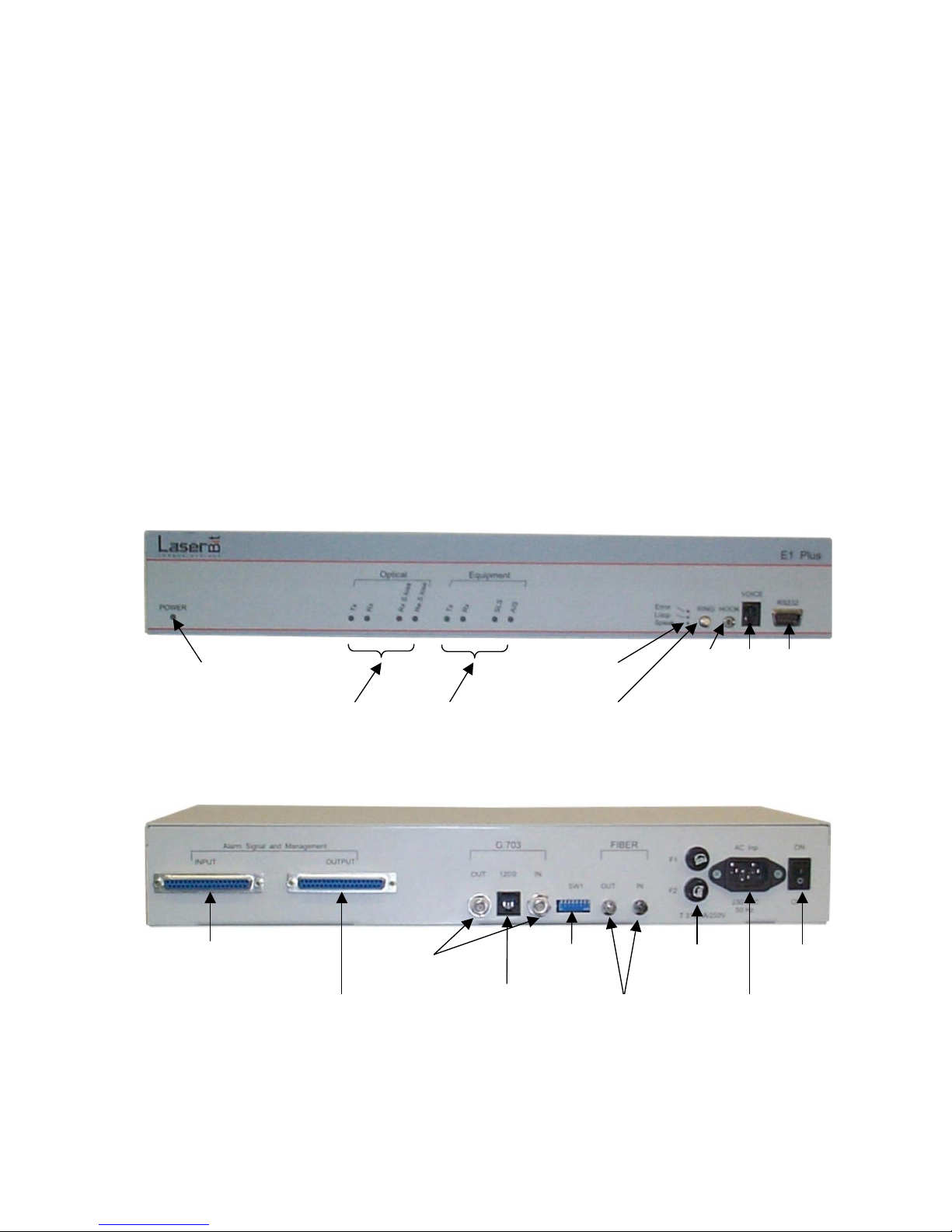
3. Configuration
Before connecting the E1 Plus device to the G.703 network it should be
configured to work properly with the local E1 equipment. All E1 Plus units are
pre-configured in the factory with the following settings:
G.703 interface
Line interface: Unbalanced, 75 Ohm BNC connection
Line coding: HDB3
Service channel
RS-232 interface: 9600, 8, 1, NP
Voice port: Panasonic handset
3.1 Location of connectors and indicators
Figure 4. E1 Plus unit front panel
Figure 5. E1 Plus unit rear panel
Power LED
RS-232 port
RJ-11 phone
handset
On-hook
switch
“Attention” push
button
Service channel
status LED’s
E1 line
status LED’s
DB-37
MGM IN
DB-37
MGM OUT
BNC
G.703
RJ-11
G.703
SW 1
E1 conf.
DIP SW
ST
Fiber port
Fuses
Power
switch
Power
connector
Optical line
status LED’s
Page 15
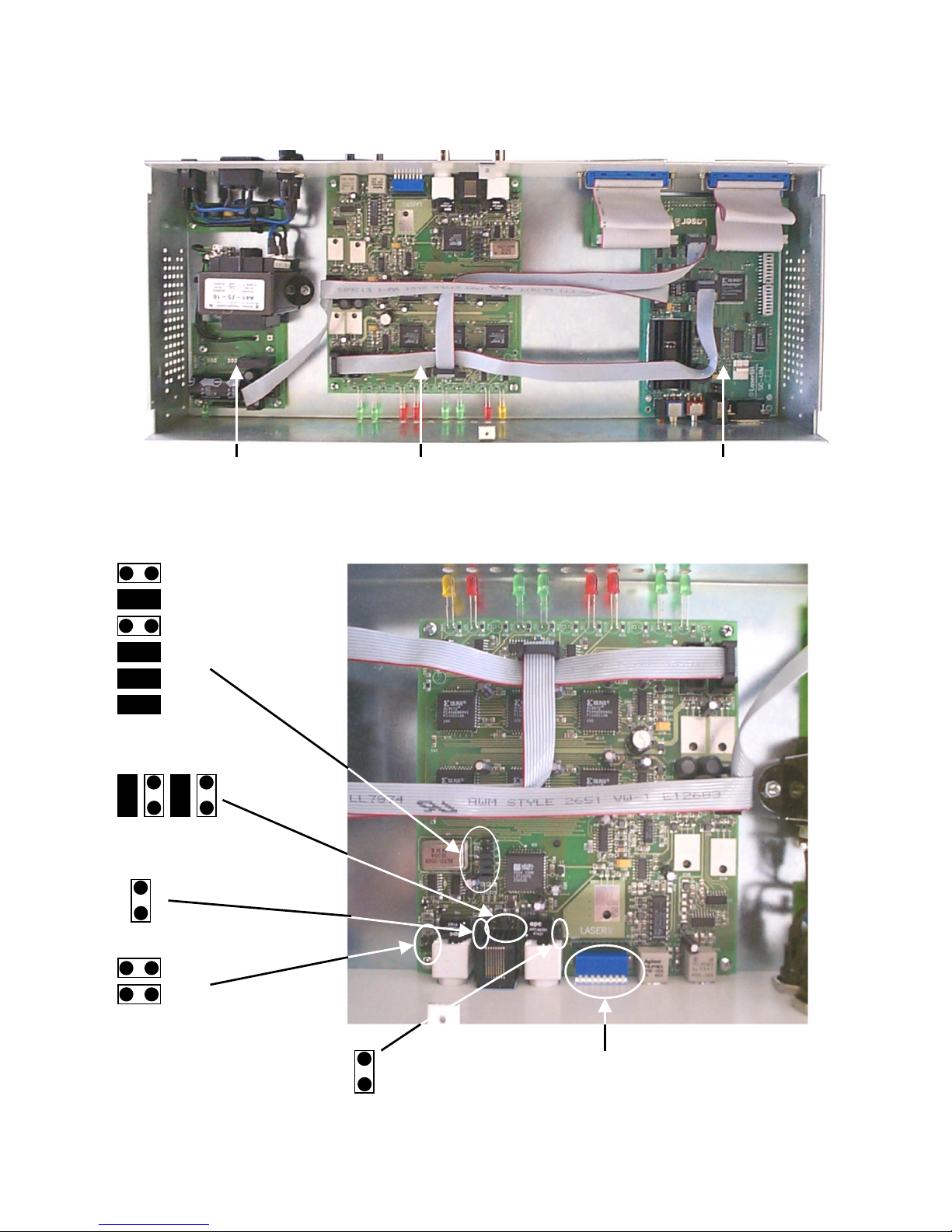
3.2 E1 Plus unit internal module arrangement
3.3 Configuration Jumpers – E1SC-MM
PSU E1SC-MM E1SC-UIM
J1
J2
J3
J4
J5
J6
J9 J10 J11 J12
J7
J8
Page 16
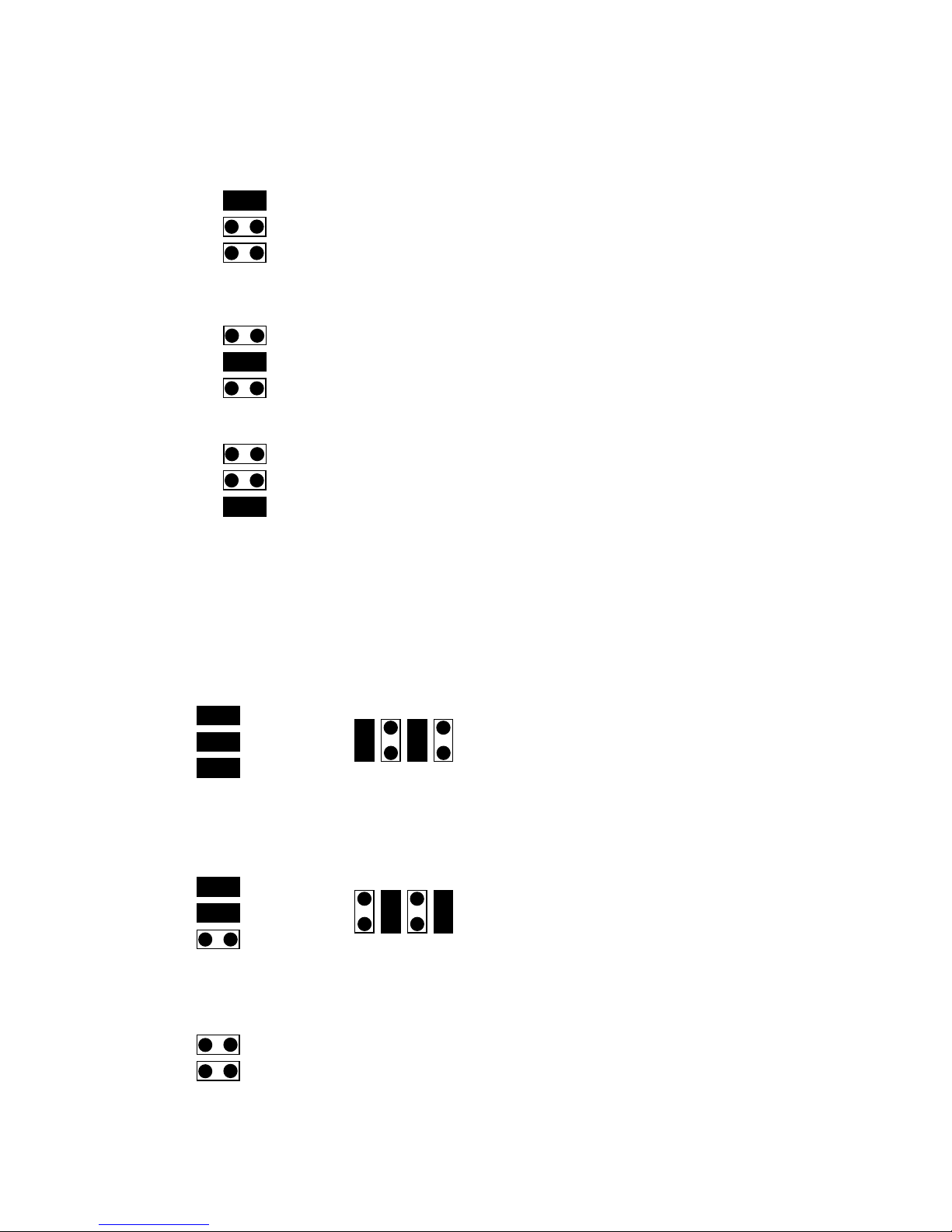
Jitter attenuator settings (J1, J2, J3)
Jitter attenuator disabled
The jitter attenuation circuit is placed in the receiver paths of copper side*
The jitter attenuation circuit is placed in the transmit paths of copper side
These three jumpers must not be installed together in the same time, only one of
them.
E1 line settings (J4, J5, J6, J9, J10, J11, J12)
75 Ohm balanced operation*
120 Ohm unbalanced operation
Line equalization (J7, J8)
Factory setting, do not change.
J1
J2
J3
J1
J2
J3
J1
J2
J3
J4
J5
J6
J9 J10 J11 J12
J4
J5
J6
J9 J10 J11 J12
J7
J8
Page 17
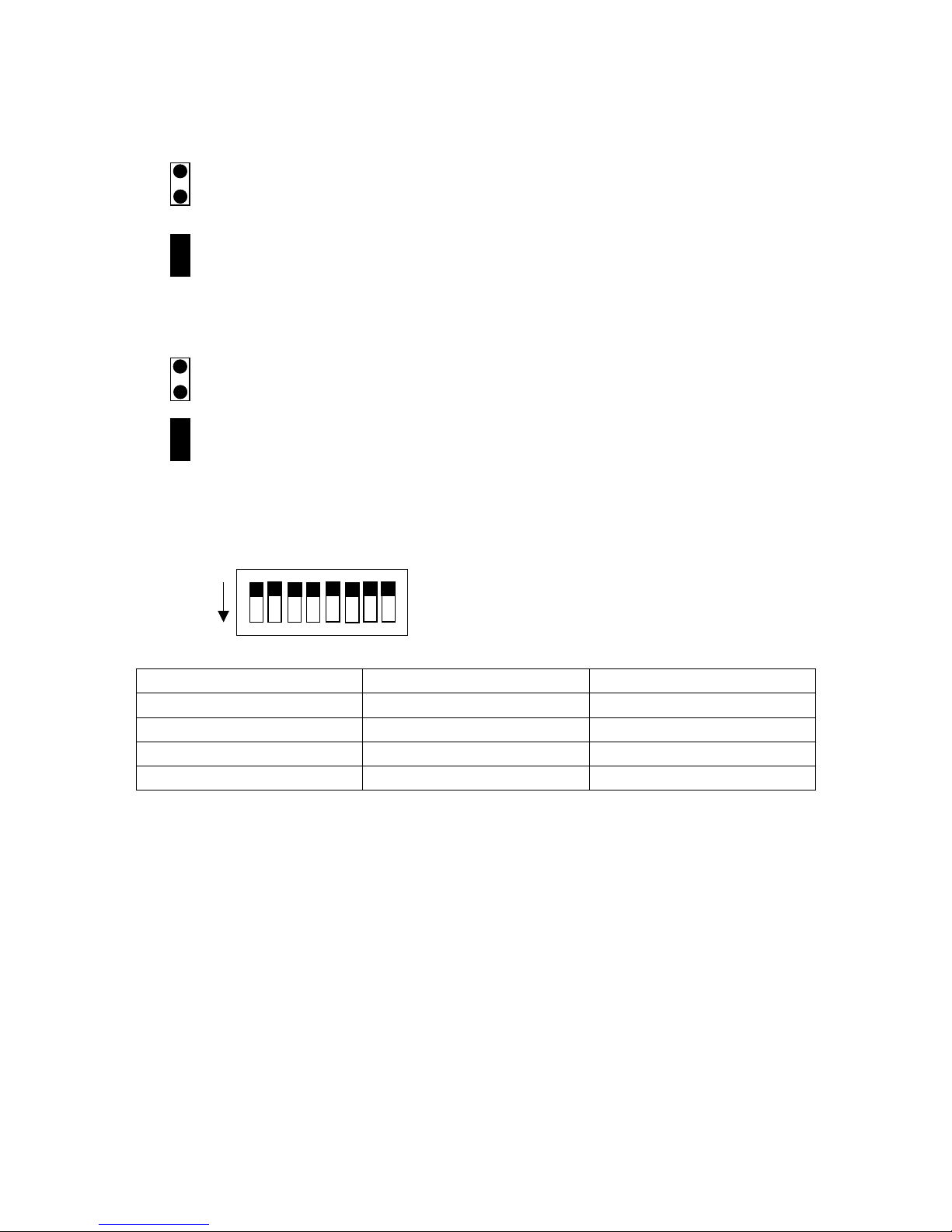
TX Logic GND
Signal output is not connected to the logic ground*
Signal output is connected to the logic ground. Use this
setting if it is required by the network operator.
RX Logic GND
Signal input is not connected to the logic ground*
Signal output is connected to the logic ground. Use this
setting if it is required by the network operator.
DIP Switch settings (SW1)
Switch No. ON OFF
1 AMI HDB3*
2 E1 line loop back Normal Operation*
3 Optical loop back Normal Operation*
4-8 N/A N/A
Asterisk (*) denotes factory setting.
J13
J
14
On
Page 18
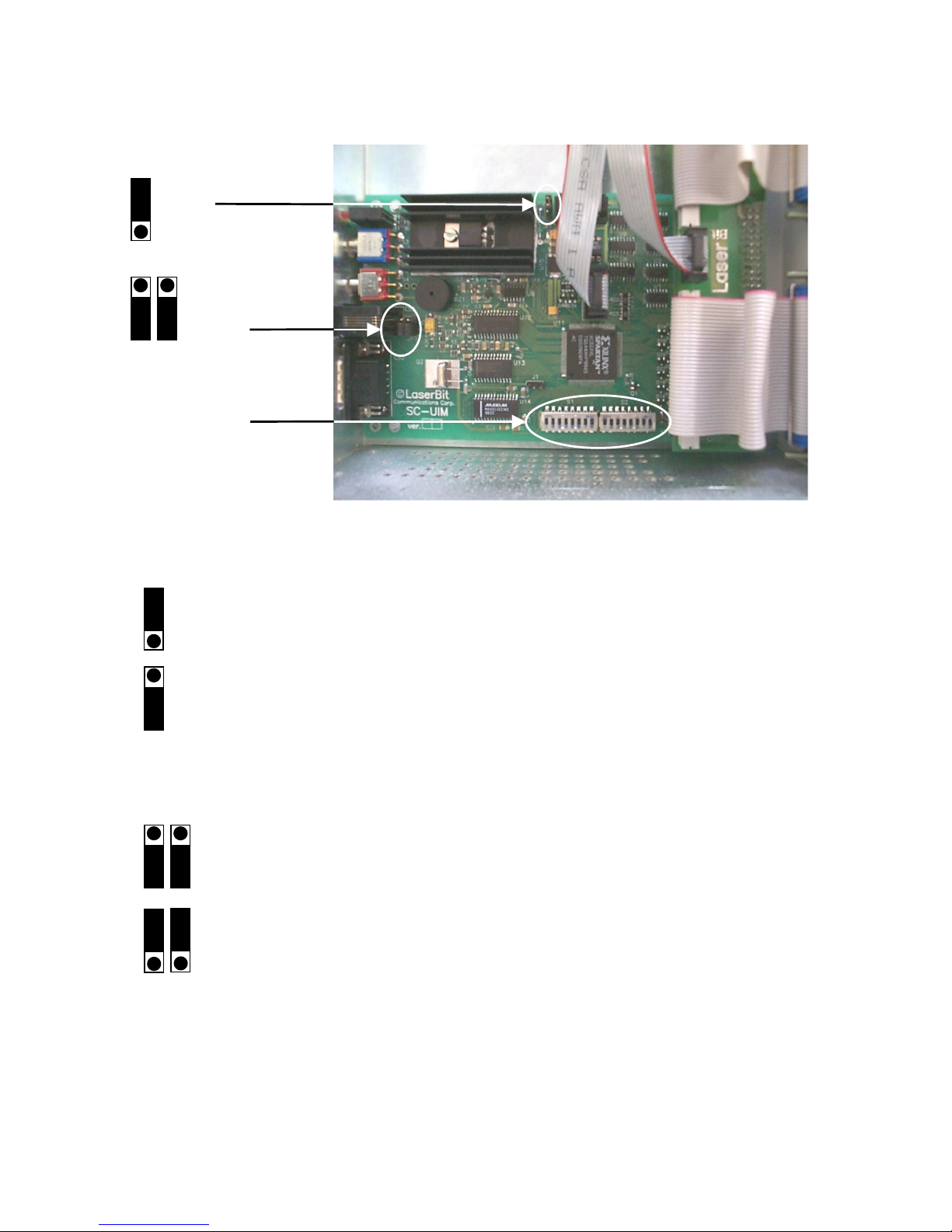
3.4 Configuration Jumpers – E1SC-UIM
Power source selector (JP2)
Locally stabilized voltage (+5V)*
Incoming voltage (+5V)
Handset MIC polarity
Panasonic type handset
*
Siemens type handset
Switch block
S1, S2
J
P1
J
P2
J
P2
J
P2
Page 19
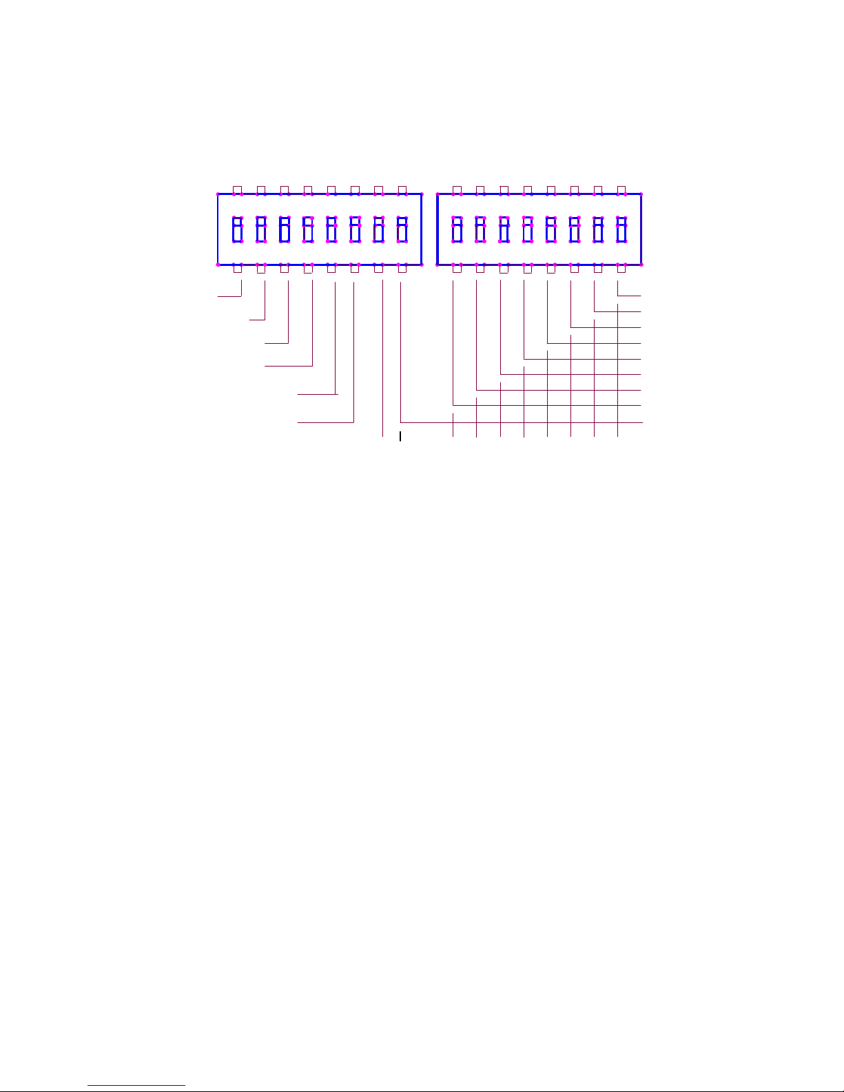
3.5 Service channel configuration settings (S1, S2)
Factory setting : 0 0 0 0 0 0 0 0 1 0 1 0 0 1 1 0
SerIn
: Method of handling the inbound 24 bit low speed signaling data
OFF – 24 signaling bits are taken from the parallel input*
ON – 24 signaling bits are taken from the serial input
RefClkSel
: Reference Closk Source selection for the ADPCM PLL
OFF – data channel receive clock (RXC)*
ON – data channel transmit clock (TXC)
LocalLoop
: Local Loop Mode selection
OFF – Normal mode*
ON – Test mode
ClkMaster
: Receive and Transmit clock source
OFF – Normal Mode (incoming RXC and TXC)*
ON – Test Mode (internal RXC and TXC)
Init_on_Error
: behavior of the signaling bits on ERROR condition
OFF – all bits keep their previous state*
ON – all bits become inactive
RemoteControl
: RS-232 configuration mode
OFF – configuration through S1,S2 switches*
ON – configuration through the internal control bus (future extension)
1
StationAddress:
2
ON
S2
1
A4
83
A2
5
BPC1
RefClkSel
A1
ClkMaster
HWContro
l
A5 A0
RemoteControl
Baud2
7
Baud3
Baud1
3
ParOdd
A7A9
56
ON
BPC2
4
SerIn
A6
Parity
72 6
S1
8
StopBit
LocalLoop
A3
4
A8
Init_on_Error
Page 20

Multifunction Switches (S1[7-8], S2[1-8])
If RemoteControl=OFF
S1[7] – N/A
S1[8] - S2[1-8] – RS-232 configuration switches
If RemoteControl=ON
S1[7-8] - S2[1-8] – Station address for remote management
S1[7] – A9 … S2[8] – A0
HWControl
: RTS/CTS flow control
OFF – Flow control disabled*
ON – Flow control enabled
Baud1, Baud2, Baud3
: RS-232 baud rate
0 0 0 300 Baud
0 0 1 600 Baud
0 1 0 1200 Baud
0 1 1 2400 Baud
1 0 0 4800 Baud
1 0 1 9600 Baud*
1 1 0 19200 Baud
1 1 1 38400 Baud
Parity
: parity handling on the RS-232 line
OFF – Parity checking and parity bit generation is disabled*
ON – Parity checking and parity bit generation is enabled
ParOdd
: Parity selection
OFF – Odd Parity*
ON – Even Parity
BCP1, BCP2
: Character length
0 0 5 bits / character
0 1 6 bits / character
1 0 7 bits / character
1 1 8 bits / character
*
StopBit
: Number of stop bits
OFF – 1 stop bit (in case of 5 bits/character 1,5 stop bit)
*
ON – 2 stop bits
Page 21

4. Technical specifications
E1 Line
Interface: G.703
Nominal bit rate: 2048 kbit/s
Bit rate tolerance:
±
50 ppm
Line code: AMI/HDB3
Connector: BNC 75 Ohm/RJ-45 120 Ohm
Optical
820 nm multimode
TX Power: -15 dBm (min)
RX Sensitivity: -31 dBm
Connector: ST multimode
1300 nm single mode:
TX Power: -18 dBm (min)
RX Sensitivity: -31 dBm
Connector: ST single mode
Common Digital data stream
Type of traffic flow: serial, synchronous, duplex
Speed: 64 kbit/s
Interface: TTL compatible
Analogue voice channel
Frequency range: 200 – 3400 Hz
Codec: ADPCM 16 kbit/s
Characteristic:
A-law
Relevant standard: ITU-T G.726
Connector: RJ-11
Page 22

RS-232 serial channel
Type of traffic flow: serial, asynchronous, duplex
Speed: 300/600/1200/2400/9600/19200/38400 bit/s
Speed tolerance:
±
4 %
Number of data bits: 5/6/7/8
Number of start bits: 1
Number of stop bits: 1/1.5/2
Parity: Odd/Even/No parity
Flow control: HW (RTS/CTS)/No flow control
Interface: DTE
Connector: DB-9, male
Status and control signals (2x24 bits)
Type of traffic flow: serial, synchronous, duplex / parallel
Number of data bits: 24
Serial data clock: 8 kHz
Sampling period: 8 ms
Parallel data input: TTL compatible
Parallel data output: Open collector, 30 V / 40 mA
System
Power: 110 VAC / 230 VAC / -48 VDC
Dimensions (WxDxH): 435 x 206 x 65 mm (1.5 U)
Operating temperature: 0 – 50
0
C
Storage temperature: -20 – 50
0
C
Humidity: 0 – 95 % non condensed
Page 23

5. Port Pinouts
Serial RS-232 (DB-9 male)
Pin Signal Function
1 DCD Data Carrier Detected
2 RXD Received Data
3 TXD Transmitted Data
4 DTR Data Terminal Ready
5 GND Signal Ground
6 DSR Data Set Ready
7 RTS Request To Send
8 CTS Clear To Send
9 RI Ring Indicator
Handset (RJ-11)
Pin Signal Function
1 T_d Handset MIC
2 R_a Handset receiver
3 R_b Handset receiver
4 T_c Handset MIC
E1 (RJ-45)
Pin Signal Function
1 RX (A) Data Receive A
2 RX (B) Data Receive B
3 GND Ground
4 TX (A) Data Transmit A
5 TX (B) Data Transmit B
6 GND Ground
7 N/A 8 N/A -
Page 24

Alarm Signal and Management INPUT (DB-37)
Pin Signal Function Electrical
1 GND Signal ground -
20 BI-0 Status and control input TTL
2 BI-1 Status and control input TTL
21 BI-2 Status and control input TTL
3 BI-3 Status and control input TTL
22 BI-4 Status and control input TTL
4 BI-5 Status and control input TTL
23 BI-6 Status and control input TTL
5 BI-7 Status and control input TTL
24 BI-8 Status and control input TTL
6 BI-9 Status and control input TTL
25 BI-10 Status and control input TTL
7 BI-11 Status and control input TTL
26 BI-12 Status and control input TTL
8 BI-13 Status and control input TTL
27 BI-14 Status and control input TTL
9 BI-15 Status and control input TTL
28 BI-16 Status and control input TTL
10 BI-17 Status and control input TTL
29 BI-18 Status and control input TTL
11 BI-19 Status and control input TTL
30 BI-20 Status and control input TTL
12 BI-21 Status and control input TTL
31 BI-22 Status and control input TTL
13 BI-23 Status and control input TTL
32 RPHGC Phone ring contact common Relay
14 RPHG0 Phone ring contact open Relay
33 RPHG1 Phone ring contact closed Relay
15 N/A - 34 N/A - 16 N/A - 35 N/A - 17 N/A - 36 N/A - 18 N/A - 37 N/A - 19 N/A - -
Page 25

Alarm Signal and Management OUTPUT (DB-37)
Pin Signal Function Electrical
1 GND Signal ground -
20 BO-0 Status and control input Open Collector
2 BO-1 Status and control input Open Collector
21 BO-2 Status and control input Open Collector
3 BO-3 Status and control input Open Collector
22 BO-4 Status and control input Open Collector
4 BO-5 Status and control input Open Collector
23 BO-6 Status and control input Open Collector
5 BO-7 Status and control input Open Collector
24 BO-8 Status and control input Open Collector
6 BO-9 Status and control input Open Collector
25 BO-10 Status and control input Open Collector
7 BO-11 Status and control input Open Collector
26 BO-12 Status and control input Open Collector
8 BO-13 Status and control input Open Collector
27 BO-14 Status and control input Open Collector
9 BO-15 Status and control input Open Collector
28 BO-16 Status and control input Open Collector
10 BO-17 Status and control input Open Collector
29 BO-18 Status and control input Open Collector
11 BO-19 Status and control input Open Collector
30 BO-20 Status and control input Open Collector
12 BO-21 Status and control input Open Collector
31 BO-22 Status and control input Open Collector
13 BO-23 Status and control input Open Collector
32 N/A - 14 N/A - 33 N/A - 15 N/A - 34 RES Remote sync loss output Open Collector
16 RXS Local sync loss output Open Collector
35 LOOP Dual Loop input Open Collector
17 GND Signal ground Open Collector
36 N/A - 18 N/A - 37 N/A - 19 N/A - -
Page 26

6. LED Description
All the status LED’s are located in the front panel of the E1 Plus unit. The
indicators are arranged into four groups according to their function as detailed
below.
Power
The power LED (green) lights when power supplied to the device that is the unit
is connected to the appropriate power source and the power switch on the rear
panel is switched on.
Optical
Tx – Transmit indicator (green); this LED lights up when the device is
transmitting on its optical port.
RX – Receive indicator (green); this LED shows the presence of an optical
signal on the RX side of the optical port.
Rx S. Loss – Receive Sync Loss (red); this LED lights when the unit has lost the
sync of the incoming signal on the optical port.
Re S. Loss – Remote Sync Loss (red); this LED indicates that the remote unit is
sending Sync Loss Frames, which means it has lost the sync on its optical side.
Equipment
Tx – Transmit indicator (green); this LED lights up when the device is
transmitting on its E1 port. If the signals are reversed on the G.703 port e.g. the
transmitter is connected to the opposite transmitter, the indicator is blinking. If
the device detects a short circuit on the TX line the LED goes out.
Rx – Receive indicator (green); this LED lights up when the device is receiving
valid data on its G.703 interface.
SLS – Signal loss (red); this LED indicates that there is no signal present on the
RX side of the E1 port.
AIS – All ones (red); this LED is turned on when the equipment is receiving
AIS signals on the E1 line interface.
Page 27

Service channel
Error – Error indicator (red); if the ERROR LED is steadily ON, it means that
the FPGA circuit could not download its operational code. Its blinking status
indicates that other initialization error happened.
Loop – Loop back indicator (yellow); this LED lights up when the device is
turned into loop back mode.
Speak – Voice channel status indicator (green); when this LED is turned ON the
voice channel between the local and remote equipment is UP. When it blinks it
indicates that call initiation from the remote site is in progress.
Page 28

Appendix A
E1 background
The invention of the telephone in 1876 (A.G. Bell) has completely changed the
world. Today it would be difficult for us to imagine our life without the
telephone.
Even these days with the ever-growing number of computer networks and the
booming Internet, voice communication still forms the major part of the total
volume of the communication traffic.
In the early days each telephone connection required a dedicated link all the way
between two users. Shortly after the steadily growing number of subscribers led
to the development of various methods and technologies, which enabled several
telephone connections to be transmitted over a single cable. Most of the systems
at that time used Frequency Division Multiplexing (FDM) technology. Here the
idea was to modulate each telephone channel with a different carrier frequency
to shift the signals into different frequency ranges.
With ever increasing demands for higher transmission rates with better quality
and the advent of semiconductor circuits other techniques were developed. In
the 1960s, digital systems started to appear. Here the telephone channels are
separated by time using a new type of transmission method known as Pulse
Code Modulation (PCM).
The analogue signal (speech) from the telephone is first converted to a Pulse
Amplitude Modulated (PAM) signal using a process called sampling. Then
using quantization and encoding this sampled analogue (PAM) signal is
converted to a digital PCM signal. Based on the principle above the
Plesiochronous Digital Hierarchy (PDM) has been developed.
Here the 300-3400 Hz band-limited analogue signal is sampled at 8000 Hz.
Then the PAM signals are quantized using a 13-segment compression
characteristic known as A-law (in T1 systems 15-segment
µ
-law characteristic
is used). Finally the signal is encoded using an 8 bit code word format. This
source coding produces 8-bit code words at a rate of 8 kHz, giving 64 kbps data
rate. To improve the utilization of the transmission medium, the signals are
transmitted by time division multiplexing, where the code-words are interleaved
and contained in a PCM frame.
A primary frame consists of 32 code words called timeslots, which are
numbered 0 to 31. A PCM31 frame comprises of 31 timeslots used for traffic
and 1 timeslot used for synchronization.
Page 29
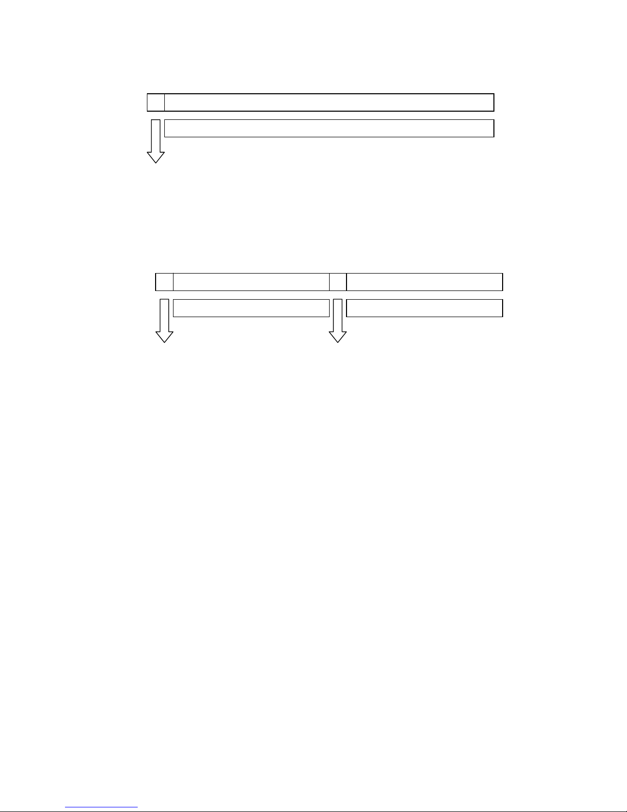
In a PCM30 system the frame comprises of 30 timeslots used for traffic and 2
code words that are used for synchronization and signaling purposes.
PDH has two primary communication systems as its foundation. These are the
T1 system based on 1544 kbps that is recommended by ANSI and the E1 system
based on 2048 kbps that is recommended by ITU-T. The T1 system is used
mainly in the USA, Canada and Japan. European and certain non-European
countries use the E1 system.
Timeslots 1 to 31
Channels 1 to 31
Frame
Synchronization
Frame
Synchronization
Timeslots 1 to 15 Timeslots 17 to 31
Timeslots 1 to 15 Timeslots 17 to 31
Signaling
Page 30

Appendix B
Characteristics of the PDH system.
Characteristics E1 T1
a Sampling frequency 8000 Hz 8000 Hz
b Number of samples per
telephone signal
8000 per second 8000 per second
c Length of PCM frame
1/b=1/8000/s=125 µs 1/b=1/8000/s=125 µs
d Number of bits in each code
word
8 8
e Telephone channel bit rate b x d=8000/s x 8 bit
= 64 kbit/s
b x d=8000/s x 8 bit
= 64 kbit/s
f Encoding/decoding
Number of segments in
characteristic
A-law
13
µ
-law
15
g Number of timeslots per
PCM frame
32 24
h Number of bits per PCM
frame
d x g = 8 x 32
= 256 bits
d x g + 1 = 8 x 24 +
1 = 193 bits
i Length of an 8 bit timeslot (c x d) / h
(125 us x 8) / 256
approx. 3.9 µs
(c x d) / h
(125 us x 8) / 193
approx. 5.2 µs
j Bit rate of time-division
multiplexed signal
b x h
8000/s x 256 bits
2048 kbit/s
b x h
8000/s x 193 bits
1544 kbit/s
Page 31
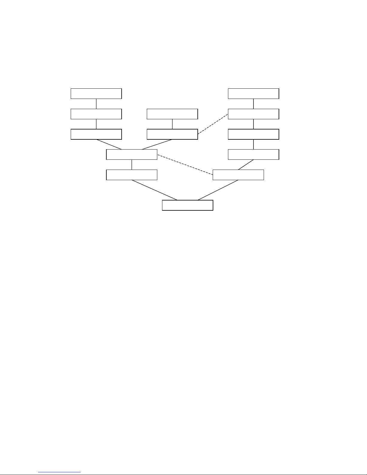
Appendix C
Summary of PDH transmission rates.
64 kb/s
1544 kb/s
6312 kb/s
2048 kb/s
8448 kb/s
34368 kb/s
139264 kb/s
564992 kb/s
44736 kb/s
274176 kb/s
32064 kb/s
97728 kb/s
397200 kb/s
x 3
x 3
x 30 x 24
x 4
x 4
x 4
x 4
x 4
x 7
x 6
x 5
x 3
x 4
Page 32

Appendix D
GLOSSARY
A bit remote (or distant) alarm indicator
AIS Alarm Indication Signal
AMI Alternate Mark Inversion
ATM Asynchronous Transfer Mode
BER Bit Error Ratio
CAS Channel Associated Signaling
CRC-4 Cyclic Redundancy Check for 2048kbit/s Systems
E1 2048kbit/s PCM communication system mainly used in Europe
E&M Exchange and Multiplex signaling
FAS Frame Alignment Signaling
G.703 ITU-T Recommendation for Physical/Electrical Characteristic for
Hierarchical Digital Interfaces
HDB3 High Density Bipolar code with a maximum of 3 zeros
ISDN Integrated Services Digital Network
ITU-T International Telecommunication Union Telecommunications
Standardization Section
MFAS Multiframe Alignment Signal
NFAS Not Frame Alignment Signal
NMFAS Not Multiframe Alignment Signal
PAM Pulse Amplitude Modulation
PCM Pulse Code Modulation
PCM30 30 channels with CAS signaling in timeslot 16
PCM30C 30 channels with CAS signaling in timeslot 16 and CRC error
checking
PCM31 31 channels
PCM31C 31 channels with CRC error checking
PDH Plesiosynchronous Digital Hierarchy
SDH Synchronous Digital Hierarchy
S/Q signal-to-quantizing noise
SONET Synchronous Optical Network
T1 1544kbit/s PCM communication system mainly used USA, Canada
and Japan
Y bit distant multiframe alarm bit
 Loading...