

Page 1

Engine Timing Tool Kit
UK
DESIGN
EU
for VW Group 1.5 TSi Petrol
Part No. 8824
Instructions
REGISTERED
DESIGN
REGISTERED
www.lasertools.co.uk
Page 2
Description
The Laser 8824 kit has been developed to allow the user to align, set and check the engine
timing of the Volkswagen group EA 211, 4-cylinder TSI petrol engines without the need to
resort to computer- based alignment tools. Made in Sheffield.
The 8824 utilises a battery-powered digital inclinometer combined with precision
manufactured adaptors and alignment tooling to ensure the camshafts are set to the
manufacturer’s specification. There should be no requirement for interaction with the
vehicle’s OBD system when following the Laser Tools procedures detailed below.
• Applications include Audi (from 2017), Seat (from 2017), Skoda (from 2017) & Volkswagen
(from 2017).
• Engine Applications include: 1.5L TSi petrol engines -DACA, DACB, DADA, DFYA, DPBA,
DPCA & DPBE.
• Engine variants include EA211, EVO 4-cylinder TSi ACT.
• Use only in connection with Laser Tools 8824 instructions.
• Camshaft pulley holding tools (Laser 7279 and 8421) or similar must be used when
loosening or tightening the camshaft pulleys.
NOTE: For 1.0L, 1.2L & 1.4L TSI petrol engine variant use Laser 8824 kit with 9103.
Warning: Hybrid Vehicles use a high voltage system. Please ensure the proper precautions
are taken when working on hybrid vehicles to avoid the risk of shock and injury.
Personnel working with hybrid and PHEV vehicles must be trained to the level required
by the vehicle manufacturer.
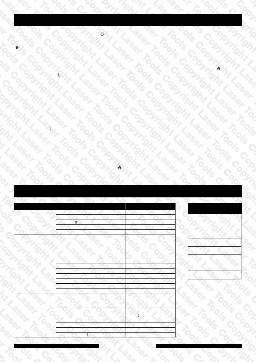
Applications
Make Model Year
AUDI
SEAT
SKODA
VOLKSWAGEN
A1 Sportback/citycarver/allstreet From 2018
A3 Saloon/Sportback/Cabrio From 2017
A3 Saloon/Sportsback From 2017
Q2 From 2018
Q3/Q3 Sportback From 2018
Arona 2017 to 2021
Ateca From 2018
Ibiza 2017 to 2021
Leon/Leon ST From 2018
Tarraco From 2019
Fabia IV From 2021
Kamiq From 2019
Karoq From 2017
Kodiaq From 2017
Octavia III/IV From 2018
Scala From 2019
Superb III From 2017
Arteon 2017 to 2020
Golf SV/Sportsvan/Estate/VII 2017 to 2021
Golf VIII/Estate From 2020
Passat From 2018
Polo 2017 to 2021
T-Cross From 2019
Tiguan/Allspace From 2019
Touran From 2018
T-Roc/Cabriolet 2017 to 2022
www.lasertools.co.uk
2
Engine Codes
1.5LT
DACA
DACB
DADA
DFYA
DPBA
DPBE
DPCA
Page 3
Kit List
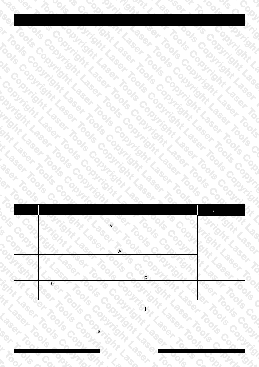
Item Comp. No. Description OEM.
A C1052 Adaptor Plate for Camshaft Housing
B C1053 Mounting Spacers & Screws for A
C C1056 Inlet Camshaft Spacer Boss (EA211 EVO)
D C1057 Exhaust Camshaft Spacer Boss (EA211 EVO)
E C1058 Inlet Camshaft Adaptor (EA211 EVO)
F C1059 Exhaust Camshaft Adaptor (EA211 EVO)
G C1060 Inclinometer Reference Bar (EA211 EVO) 1.5
H Fixing Screws for G
I C784 Inclinometer
J C735 Camshaft Rear (water pump) Sprocket Timing Pin T10504/1
K C439 Crankshaft Timing Pin T10340
L C1044 Lever Stop Pins x 2
M
C685 Tensioner Pulley Adjuster Tool T10499
VAS 611 007
For torque settings please refer to OEM derived data such
as the vehicle manufacturer’s own data or Autodata.
The use of this engine timing kit is purely down to the user’s
discretion and The Tool Connection Ltd. cannot be held
responsible for any damage caused whatsoever.
www.lasertools.co.uk
3
Page 4

Instructions for use
NOTE: When loosening and tightening any pulley or sprocket fixing, do not use the camshaft
or crankshaft alignment tools to torque against. ALWAYS use the correct sprocket/pulley
holding tool.
IMPORTANT: BEFORE EACH USE:
8824 – Digital Camshaft Angle Setting Kit – Preparation and Clamp adjustment.
Before each use the clamping action of the adaptor locking levers may require adjustment.
The following procedure should be used to set the clamping force (see image PREP 1):
Assemble the 8824 camshaft locking tools on a bench as shown in image PREP 1a, including
fitting the camshaft adaptor into the assembly.
Lock the adaptor locking levers and insert the lever stop pins as shown in image PREP 1b.
Using a 6mm hex-key socket and torque wrench check that the adaptors do not rotate when
a torque of 25Nm is applied (Image PREP 1b).
PREP 1
PREP 1a
25Nm
PREP 1b
If the adaptors rotate at less than 25Nm tighten the clamping adjuster screw as shown in
image PREP 2.
PREP 2
45o (1/8 turn)
Adjusting the Clamping force:
Unlock the levers and turn the assembly upside down to access the adjuster screws.
Note: ensure the camshaft adaptors are fully inserted into the clamps.
Adjust the clamping force using a 3mm hex key as shown in image PREP 2.
Tighten the screw by 1/8 of a turn then recheck the torque figure detailed in image PREP 1b.
www.lasertools.co.uk
4
Page 5

Vehicle Preparation
Access is required to both ends of the cam drive system which may require the removal of
some or all of the following dependent on vehicle model:
• Engine coolant.
• Engine top and bottom covers.
• Right hand front wheel and inner wheel arch.
• Coolant expansion bottle.
• Air filter housing and turbo charger pipes.
• Water pump drive belt and hoses.
Working from the transmission end of the engine remove:
• The Inlet camshaft end cover.
• Water pump (exhaust camshaft end).
Working from the belt end of the engine:
• Remove the timing belt cover.
• Remove the 5 fixing screws from the exhaust camshaft adjuster cover plate.
Initial setting of the engine (old belt in place):
Component K – Crankshaft locking pin
Locate the crankshaft locking pin blanking plug on the rear of the engine block and remove it.
Screw the crankshaft locking pin (K) into the threaded hole and tighten to 10Nm. If (K) will not
screw fully in remove it and turn the crankshaft through ¼ of a turn clockwise. Refit (K) and
tighten to 10Nm. Now turn the crankshaft clockwise until it locks against the nose of (K).
See figure 1.
FIG: 1
K
Component J – Exhaust camshaft rear sprocket timing pin:
Fit the exhaust camshaft rear sprocket timing pin (transmission end) as shown in figure 2.
If the hole in the pulley is 180 degrees out, remove (K) and rotate the crankshaft 360 degrees.
Refit (K) and fit (J) as shown.
FIG: 2
J
www.lasertools.co.uk
5
Page 6

Once the initial mechanical alignment has been set remove (J) and using a suitable pulley
holding tool remove the water pump drive pulley from the camshaft.
Check both camshaft flats are in the 12 o’clock (horizontal) position as shown in Figure 3.
FIG: 3
Fitting Camshaft Timing kit:
To accurately check the camshaft timing, it is necessary to fit the full 8824 kit to the
transmission end of the camshafts as follows:
Components G & H – Inclinometer Reference Bar:
First fit the reference bar (G) using fixing screws (H) as shown in Figure 4.
IMPORTANT: Ensure this area is clean so that the bar fits flush and touching against
the bottom of the cylinder head for the full length of the top of (G) as shown.
6
FIG: 4
G
www.lasertools.co.uk
Page 7

Components A, B, C & D – Camshaft Locking Tool Assembly:
Assemble components (A), (B), (C) and (D) as shown in Figure 5.
Then mount the assembly on to the engine with the holes in C & D
facing up as shown in Figure 6.
FIG: 5
Components E & F – Camshaft Adaptors:
Insert the 2 camshaft adaptors (E & F). See Figure 6.
NOTE: it is important that (E) & (F) are fitted to the correct camshaft as dictated by
the markings. (E) must be fitted to the inlet camshaft and (F) to the exhaust camshaft.
The ends of (E) & (F) must engage properly with the camshafts.
Tighten the clamping screws on both (E) & (F) using a 6mm hex key as shown in Figure 7.
Max torque 15Nm.
FIG: 6
www.lasertools.co.uk
7
Page 8
FIG: 7
NOTE: Ensure the adaptors (E) & (F) are tight
on the camshafts and cannot be rotated.
Checking timing:
Component I – Inclinometer:
Place the inclinometer (I) on a flat surface and switch it on.
Allow the reading to stabilise.
With the engine set as detailed above place the inclinometer (I) upside
down up against the inclinometer reference bar (G) as shown in Figure 8
and allow to stabilise.
Holding the inclinometer against (G) press ZERO to set the inclinometer to 00.0.
FIG: 8
Move the inclinometer to the flat on the inlet adaptor (the correct way up) and record the
value shown. Repeat for the exhaust adaptor and record the readings. See Figure 9.
NOTE: always record the direction of the reading.
Arrow up (
Arrow down (
) = Negative angle,
) = Positive angle.
NOTE: The arrows on the inclinometer indicate the direction to go to find zero.
www.lasertools.co.uk
8
Page 9
FIG: 9
Compare recorded reading to the vehicle manufacturer engine specific data.
Example: Engine code DADA (1.5lt)
Specified inlet timing angle -0.3° +/- 1.2° = range of -1.5° (
Specified exhaust timing angle +1.1° +/- 1.2° = range of -0.1° (
) to +0.9° ( )
) to +2.3° ( )
WARNING: Figures quoted above are for demonstration purpose only. Please refer
tospecific engine tolerances as quoted by the vehicle manufacturer or Autodata.
Camshaft drive belt removal:
With the 8824 kit fitted as shown in Figure 7, lock the camshaft adaptors (E) and (F) by lifting
the red and blue locking levers and inserting the lever stop pins (L) as shown in Figure 10.
FIG: 10
Using an appropriate pulley holding tool loosen the inlet camshaft adjuster control valve.
See Figure 11.
Using an appropriate pulley holding tool loosen the exhaust camshaft pulley bolt and replace
with new (finger tight only). See Figure 11.
NOTE: For camshaft holding Laser Tools recommend Laser 8421 used with Laser 7279.
www.lasertools.co.uk
9
Page 10

FIG: 11
NOTE: the exhaust pulley fixing bolt should not be reused.
WARNING: Never attempt to loosen or tighten against the 8824 camshaft or crankshaft
locking tools.
Component M – Tensioner Pulley Adjuster Tool
• With the crankshaft still seated against the crankshaft locking pin (K) and the camshaft
locked as shown in Figure 10 release the timing belt tensioner using the tensioner adjuster
tool (M). See Figure 12.
FIG: 12
M
• Remove the belt leaving the pulleys on the camshaft with their fixings finger-tight.
Camshaft drive belt fitting:
NOTE: Before fitting the new belt ensure the camshaft adjuster control valve and
crankshaft sprocket are in good order as described in the manufacturer’s instructions.
With the crankshaft still seated against the crankshaft locking pin (K) and both camshafts
locked as shown in Figure 10, fit the new belt to the crankshaft pulley only.
Fit the lower timing belt cover and crankshaft pulley as detailed in the manufacturer’s
instructions using an appropriate crankshaft pulley holding tool (see Laser 6998). Tighten the
crankshaft pulley bolt to the correct torque and angle (see manufacturer’s data).
Fit the new belt to the rest of the pulleys in the following order – guide pulley, exhaust
camshaft and the inlet camshaft.
Check the camshaft pulley fixings are finger-tight only and the pulleys can turn independently
of the camshafts. Tension the belt using the tensioner pulley adjuster (M) as detailed in the
manufacturer’s instructions.
www.lasertools.co.uk
10
Page 11

Check the camshaft adaptor angles as detailed in the Checking Timing section above to
ensure the camshafts have not moved (Figures 8 and 9).
Using the appropriate holding tools tighten the camshaft pulley fixings to the manufacturers
specified torque (Assembly torque only, not full final torque, in this example around 20Nm).
NOTE: Every time the angles are checked always zero the inclinometer using the
reference bar (G) figure 8 & 9. This is to ensure any change in the angle of the engine
when for example raising or lower the vehicle ramp is compensated for.
Final checks:
Release the red and blue locking levers by removing the lever stop pins (L) as shown in
Figure 13.
FIG: 13
Remove the crankshaft locking pin (K).
Turn the crankshaft 2 complete turns stopping just before returning to the TDC position
and reinsert the crankshaft locking pin (K). Turn the crankshaft until it stops against (K).
Recheck the camshaft angles as detailed in the Checking Timing section (Figures 8
and 9) on pages 8 and 9.
Compare the reading to the manufacturer specification. If no adjustment is required the
camshaft pulleys can be tightened to the manufacturer’s full specification.
If adjustment is required perform the following procedure:
Initial Camshaft Setting & Calculation of Correction Angles:
With the crankshaft still set against the crankshaft pin (K) lock the camshafts as detailed in
Figure 10. Using an appropriate pulley holding tool loosen the inlet camshaft adjuster control
valve and finger tighten. See Figure 11.
Using an appropriate pulley holding tool loosen the exhaust camshaft pulley bolt and finger
tighten. See Figure 11.
NOTE: For camshaft holding Laser tools recommend Laser 8421 used with Laser 7279.
www.lasertools.co.uk
11
Page 12

Place the inclinometer (I) upside down up against the inclinometer reference bar (G) as shown
in Figure 8 and allow to stabilise.
Holding the inclinometer against (G) press ZERO to set the inclinometer to 00.0° and move
the inclinometer to sit it on the flat of the inlet camshaft adaptor (E) (the correct way up).
Insert a 6mm hex key into the end of the inlet camshaft adaptor (E) and while holding the
hex key, unlock the inlet camshaft by removing the lever stop pin (L – inlet only).
Adjust the position of the camshaft using the hex key until zero (00.0°) is shown on the
inclinometer and then lock the adaptor with the locking lever and reinsert the lever stop
pin (L).
Repeat this procedure for the exhaust cam.
Once both camshafts are set to zero and locked, tighten the camshaft pulley fixings to 20Nm.
NOTE: For camshaft holding Laser Tools recommend Laser 8421 used with Laser 7279.
Re-check that both camshafts are still reading Zero, if not repeat the above process.
Release the red and blue locking levers by removing the lever stop pins (L) as shown in figure
13. Remove the crankshaft locking pin (K).
Turn the crankshaft 2 complete turns stopping just before returning to the TDC position and
reinstall the crankshaft locking pin (K). Turn the crankshaft until it stops against (K).
Recheck the camshaft angles as detailed in the Checking Timing section (Figures 8 and 9)
on pages 8 and 9.
Take note of the recorded values, these will be used to calculate the correction angle.
The correction angles for each camshaft have to be calculated. This is using the
following equation.
(Specified Angle) – (Current Angle) = Correction Angle
See examples opposite:
Example calculation
Use vehicle manufacturer’s engine specific data and measured camshaft timing angle
from previous section.
12
www.lasertools.co.uk
Page 13
EXAMPLE ONLY:
Engine code DADA (1.5lt)
Specified Inlet timing angle -0.3° +/- 1.2° (manufacture data, engine specific)
Specified Exhaust timing angle +1.1° +/- 1.2°
Current Inlet Camshaft Timing Angle (Measured Angle) = (
0.9°) -0.9°
(Specified Angle) – (Current Angle) = Inlet Correction Timing Angle
(-0.3°) – (-0.9°) = +0.6° turn 0.6° clockwise from Current Angle.
Inlet Calc.
NOTE: Arrows indicate the direction to rotate to reach zero.
Specified = -0.3
Actual = -0.9
Correction = +0.6
Current Exhaust Camshaft Timing Angle (Measured Angle) = ( 1.0°) -1.0°
(Specified Angle) – (Current Angle) = Exhaust Correction Timing Angle
(+1.1°) – (-1.0°) = +2.1° turn 2.1° clockwise from Current Angle.
Exhaust Calc.
NOTE: Arrows indicate the direction to rotate to reach zero.
Specified = +1.1
Actual = -1.0
Correction = +2.1
Final Setting of timing:
NOTE: Once the Correction Angle is identified, the camshafts must be set to Zero
and then adjusted from zero by the Correction Angle to compensate for the engine
manufacturer’s tolerances.
Using an appropriate pulley holding tool loosen the inlet camshaft adjuster control valve and
finger tighten. See Figure 11.
Using an appropriate pulley holding tool loosen the exhaust camshaft pulley bolt and finger
tighten. See Figure 11.
NOTE: For camshaft holding Laser Tools recommend Laser 8421 used with Laser 7279.
www.lasertools.co.uk
13
Page 14

Place the inclinometer (I) upside down up against the inclinometer reference bar (G) as shown
in figure 8 and allow to stabilise.
Holding the inclinometer against (G) press ZERO to set the inclinometer to 00.0° and move
the inclinometer to sit it on the flat of the inlet camshaft adaptor (E) (the correct way up).
Insert a 6mm hex key in to the end of the inlet camshaft adaptor (E) and adjust the position of
the camshaft using the hex key until the corresponding Calculated Correction Timing Angle
is shown on the inclinometer and then lock the adaptor with the locking lever and insert the
lever stop pin (L).
Repeat this procedure for the exhaust cam.
Once both camshafts are set to zero and locked, tighten the camshaft pulley fixings to 20Nm.
NOTE: For camshaft holding Laser Tools recommend Laser 8421 used with Laser 7279.
Recheck Timing:
Recheck the camshaft angles as detailed in the Checking Timing section (figures 8 and 9)
on pages 8 and 9.
Compare the reading to the manufacturer specification.
14
www.lasertools.co.uk
Page 15

Safety Warnings - please read
• If the engine has been identified as an
Interference engine, damage to the engine
will occur if the timing belt has been
damaged. A compression check of all
the cylinders should be taken before the
cylinder head(s) are removed.
• Do not turn crankshaft or camshaft when
the timing belt/chain has been removed.
• To make turning the engine easier,
remove the spark plugs/glow plugs
or injectors.
• Observe all tightening torques.
• Do not turn the engine using the camshaft
or any other sprocket.
• Disconnect the battery earth lead (check
Radio code is available).
• Do not use cleaning fluids on belts,
sprockets or rollers.
• Some toothed timing belts are not
interchangeable. Check the replacement
belt has the correct tooth profile.
• Always mark the belt with the direction of
running before removal.
• Do not lever or force the belt onto
its sprockets.
• Do not use timing pins to lock the
engine when slackening or tightening the
crankshaft pulley bolts.
• ALWAYS REFER TO A REPUTABLE
MANUFACTURERS WORKSHOP
MANUAL.
www.lasertools.co.uk
15
Page 16

Our products are designed to be used correctly and with care for the purpose for which they
are intended. No liability is accepted by the Tool Connection for incorrect use of any of our
products, and the Tool Connection cannot be held responsible for any damage to personnel,
property or equipment when using the tools. Incorrect use will also invalidate the warranty.
If applicable, the applications database and any instructional information provided has been
designed to offer general guidance for a particular tool’s use and while all attention is given
to the accuracy of the data no project should be attempted without referring first to the
manufacturer’s technical documentation (workshop or instruction manual) or the use of a
recognised authority such as Autodata.
It is our policy to continually improve our products and thus we reserve the right to alter
specifications and components without prior notice. It is the responsibility of the user to
ensure the suitability of the tools and information prior to their use.
www.lasertools.co.uk
8824_Instructions_V3
 Loading...