

Page 1
Engine Timing Tool Kit
Volvo 1.5L Petrol
Part No. 8793
Instructions
www.lasertools.co.uk
Page 2
Introduction
Applications
This kit has been specifically developed to allow the user to lock the post 2019 1.5L Volvo
B3154 petrol engines in their “timed” position so the camshaft drive belt can be safely
removed and replaced and the engine timing set and checked.
• Applications include: Volvo XC40 Recharge (from 2020), T2 (from 2019), T3 (from 2018), T4
“Twin Engine” (2019-2020), T5 “Twin Engine” (2019-2020), Recharge PHEV (from 2020).
• Engine Applications include: 1.5L Petrol B3154T5, B3154T9, B3154T, B3154T2, B3154T4,
B3154T7, B3154T10.
• Equivalent to: OEM refs. 999 7690, 999 7697, 999 7676 & 999 7675.
• Use in accordance with instructions supplied.
Components
Manufacturer Model Type Year Engine Codes
Volvo XC40
Always refer to the website for most up to date applications:
Recharge T5 From 2020
T2 From 2019
T3 From 2018
T4 Twin Engine 2019 - 2020
T5 Twin Engine 2019 - 2020
Recharge PHEV From 2020
www.lasertools.co.uk/product/8793
1.5L
B3154T5
B3154T9
B3154T
B3154T2
B3154T4
B3154T7
B3154T10
Instructions
The following instructions are for guidance only. Please refer to OEM derived data such as
the vehicle manufacturers’ own data or Autodata.
The use of this engine timing tool kit is purely down to the user’s discretion and The Tool
Connection Ltd. cannot be held responsible for any damage caused whatsoever.
Ref. Comp. Code OEM Ref. Description
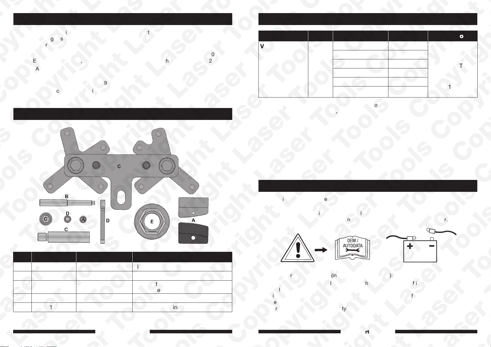
A C1025 999 7690, 999 7697 Flywheel Locking tools (3 parts)
B C1026 999 7676 Crankshaft Alignment Pin
C C1027 999 7675
D C1028 N/A Cambelt Retaining Tool
E C1029 999 7674 Camshaft Holding Tool
www.lasertools.co.uk
Camshaft Sprocket Locking
& Alignment Tool
Warning: Hybrid drive vehicles (including PHEV & MHEV):
Where the vehicle is a hybrid electric vehicle there may be a risk of injury due to electric
shock. Please ensure all manufacturers’ safety recommendations are followed at all times
including any relevant HV disconnection processes and the use of appropriate PPE as
specified by the vehicle manufacturer. No liability is accepted by the Tool Connection for
injury or shock to personnel, property or equipment, however caused.
www.lasertools.co.uk
32
Page 3
InstructionsInstructions
NOTE: When loosening and tightening pulley or sprocket fixings do not use the
camshaft or crankshaft alignment tools to torque against. ALWAYS use a sprocket
holding tool and /or flywheel holding tool.
Warning: Hybrid and PHEV vehicles - risk of electric shock or other injuries.
Ensure the ignition is switched off and keys/fob removed from the vehicle and
isolated, 12v battery should be disconnected and (where the manufacturer requires)
the high voltage battery should be isolated before working on or around high voltage
components.
Preparation:
• Raise the vehicle and secure the vehicle.
• Remove the right hand wheel and inner wheel arch.
• Remove the engine upper and lower engine covers.
• Remove flywheel dust cover.
• Remove auxiliary drive belt cover and cam belt covers.
• Coolant expansion tank - Unbolt and move to one side.
Component Descriptions
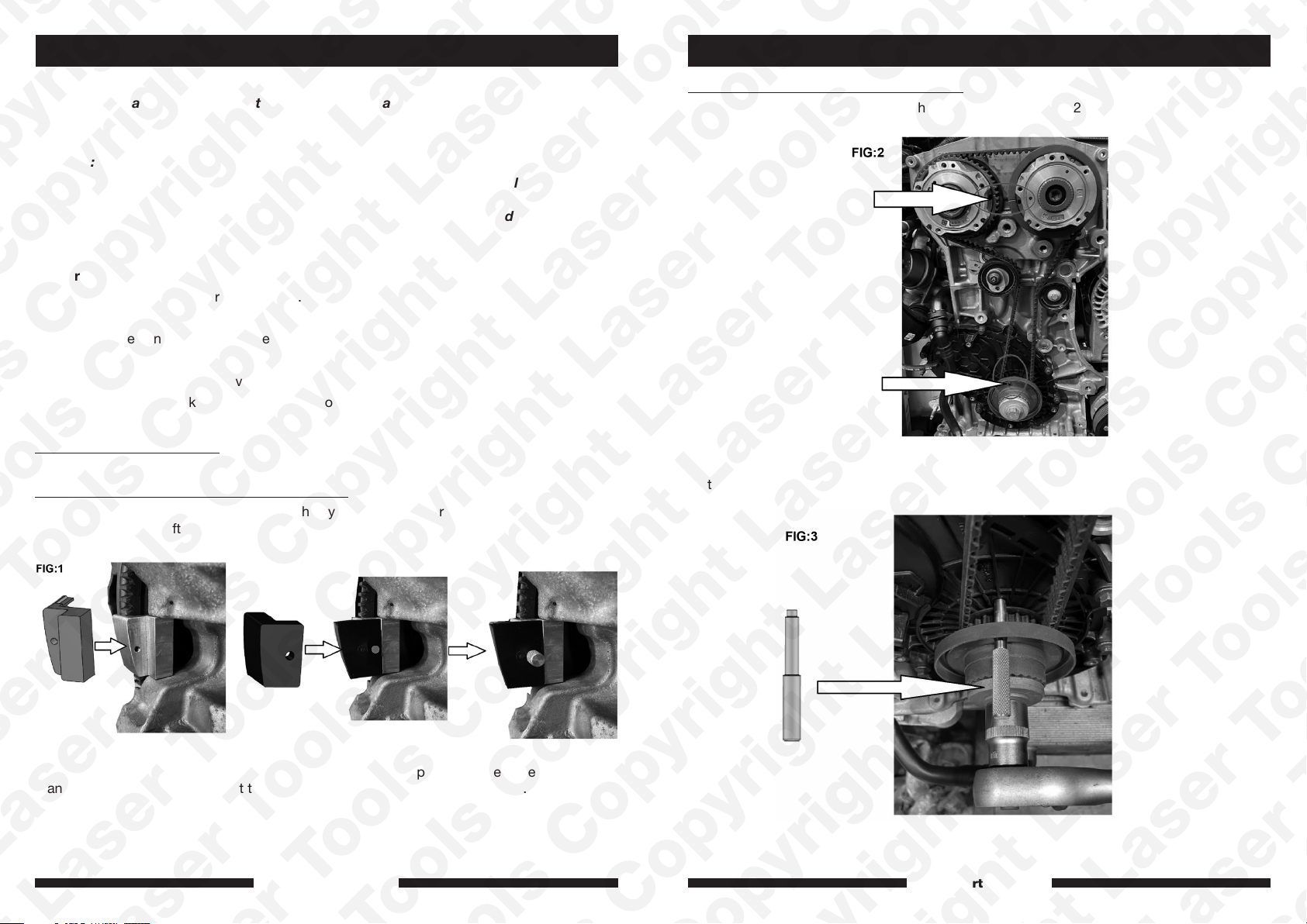
Component A – Flywheel Locking Tool (3 parts)
Assemble the flywheel locking tools on to the flywheel from underneath the engine between
the nearside drive shaft and the engine block. See Figure 1.
Component B - Crankshaft Alignment Pin
Align the crankshaft pulley and camshafts as shown in Figure 2.
Fit the crankshaft alignment pin as shown in Figure 3.
With the flywheel locked, slacken and remove the crankshaft pulley bolt, remove the
crankshaft pulley and loosely refit the crankshaft bolt. Remove the locking tool.
www.lasertools.co.uk www.lasertools.co.uk
54
Page 4
Component C - Camshaft Sprocket Locking & Alignment Tool
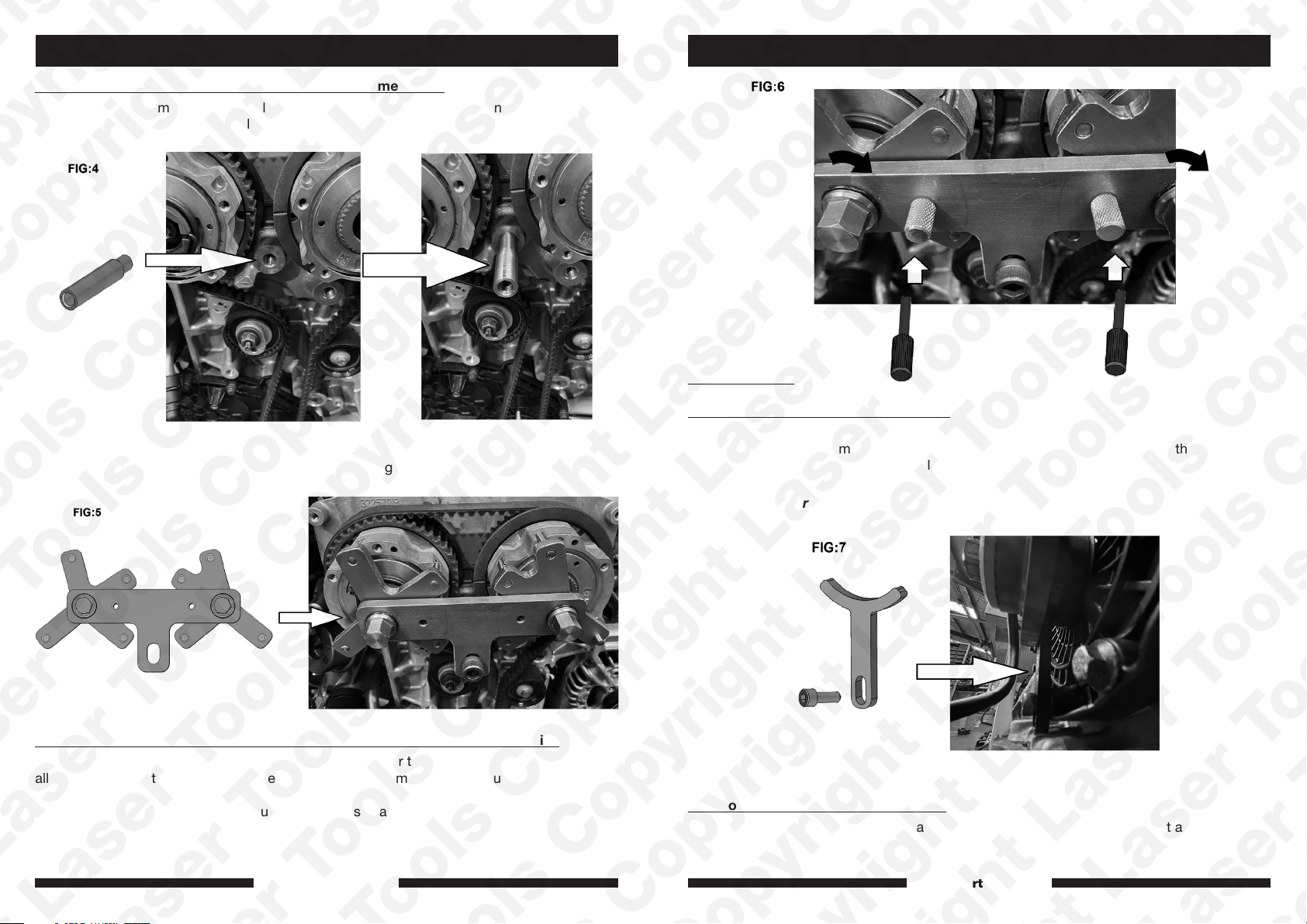
Before fitting the camshaft sprocket locking tool (C) remove the locking pins and fit the
camshaft sprocket locking tool holding boss as shown in Figure 4.
Fit the camshaft sprocket locking tool (C) as shown in Figure 5.
InstructionsInstructions
Fitting New Belt
Component D - Cambelt Retaining Tool
Fit the new belt starting at the crankshaft. Fit the belt around the bottom of the crankshaft
sprocket and use the cambelt retaining tool (D), as shown in Figure 7, to keep the belt in
place while fitting around the other pulleys in an anti-clockwise direction, keeping the belt a
tight as possible. Release the tensioner pulley pin and remove all timing tools.
NOTE: Remember to remove the cambelt retaining tool.
Component C - Camshaft Sprocket Locking & Alignment Tool – Alignment Pins
Before removing the old belt, using an appropriate spanner turn the exhaust camshaft to
allow the alignment pin to be fitted. Repeat for the inlet camshaft. See Figure 6.
Back-off the belt tensioner and remove the old belt.
Fit the new tensioner pulley, guide pulley and fixings in accordance with the manufacturer
instructions.
www.lasertools.co.uk www.lasertools.co.uk
Component E – Camshaft Holding Tool
Use component E to hold the camshaft adjuster when removing the camshaft adjuster bolts.
76
Page 5

Safety Warnings - please read
Warning – Incorrect or out of phase engine timing can result in damage to the valves.
It is always recommended to turn the engine slowly, by hand, and to re-check the
camshaft and crankshaft timing positions.
• If the engine has been identified as an
Interference engine, damage to the engine
will occur if the timing belt has been
damaged. A compression check of all
the cylinders should be taken before the
cylinder head (s) are removed.
• Do not turn crankshaft or camshaft when
the timing belt/chain has been removed.
• To make turning the engine easier,
remove the spark plugs/glow plugs or
injectors.
• Observe all tightening torques.
• Do not turn the engine using the camshaft
or any other sprocket.
• Disconnect the battery earth lead (check
Radio code is available).
• Do not use cleaning fluids on belts,
sprockets or rollers.
• Some toothed timing belts are not
interchangeable. Check the replacement
belt has the correct tooth profile.
• Always mark the belt with the direction of
running before removal.
• Do not lever or force the belt onto its
sprockets.
• Do not use timing pins to lock the
engine when slackening or tightening the
crankshaft pulley bolts.
• ALWAYS REFER TO A REPUTABLE
MANUFACTURERS WORKSHOP
MANUAL.
Our products are designed to be used correctly and with care for the purpose for which they are
intended. No liability is accepted by the Tool Connection for incorrect use of any of our products, and the
Tool Connection cannot be held responsible for any damage to personnel, property or equipment when
using the tools. Incorrect use will also invalidate the warranty.
If applicable, the applications database and any instructional information provided has been designed
to offer general guidance for a particular tool’s use and while all attention is given to the accuracy
of the data no project should be attempted without referring first to the manufacturer’s technical
documentation (workshop or instruction manual) or the use of a recognised authority such as Autodata.
It is our policy to continually improve our products and thus we reserve the right to alter specifications
and components without prior notice. It is the responsibility of the user to ensure the suitability of the
tools and information prior to their use.
8793_Instructions_V4
www.lasertools.co.uk
 Loading...