

Page 1
OBD Breakout Box
& Signal Detector
Instructions
Part No. 8611
www.lasertools.co.uk
Page 2
A vehicle OBD (on board diagnostic) socket-protocol signal-identifier and breakout box designed to be used in series with OBDII/EOBDII diagnostic equipment.
The Laser 8611 allows the technician to test the signal data via an oscilloscope or
multimeter whilst also accessing the vehicle on-board diagnostic data using the
16-pin OBD socket on the breakout box. This box also features a digital readout
that allows the user to switch between the pins and identify whether pins are live or
earth, and what type of voltage they carry. To prevent damage to your diagnostic
scan tool any abnormality, such as shorting or reverse-polarity at the pins, will be
discovered before the scan tool is plugged in.
Compatible with 12 and 24 volt systems; plugs directly into the vehicles OBD
socket. Can be used with multimeter probes or 2mm and 4mm banana probes —
adaptors included.
Selectable pin voltage digital indicator. Pin 16 is fused to protect diagnostic
equipment from vehicle wiring errors. Protocol indicator lights on appropriate pins:
Pin 6 = CAN High, Pin 14 = CAN Low, Pin 2=VPW+, PWM+, Pin 10 = PWM-, Pin 7 =
K-LINE and Pin 15 = L-LINE.
Precautions:
Always refer to these instructions before use and always refer to manufacturer’s
documentation for testing and diagnostic procedures.
No liability is accepted for incorrect use of this product — do not use the product
for tasks it is not designed for. Use the product correctly and with care. Failure to do
so may cause damage and/or personal injury and will invalidate the warranty.
ComponentsIntroduction
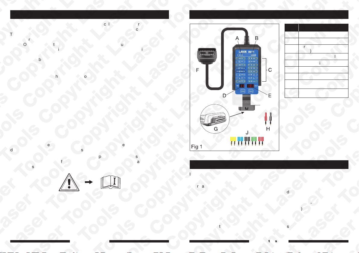
Ref. Description
A OK Signal LED
B Warning Signal LED
Probe Sockets & LEDs
C
(x 16)
D Pin Selected Display
E Voltage Display
F OBD Socket
G OBD Plug
Banana Probe Adaptors
H
(2 - 4mm)
Banana Probe Adaptors
J
(2mm)
Specifications
Input voltage: 9.0 – 32.0V DC
Maximum load: 2.0A
Overload protection: PTC Fuse (self-healing)
Reverse polarity protection: LED on pins 4 and 5 turn RED
Protocol standard: PWM (J1850); VPW (J1850); ISO 9141-2;
DIS/ISO 14230-4; CAN bus (J-2284)
Operating temperature: 0°C - 50°C (32°F - 122°F)
Permitted humidity: Less than 70%
Probe sockets: 16 outputs x 2.0mm diameter with LED indicators
OBD cable length: 72cm (28.3 inches)
2
www.lasertools.co.uk
www.lasertools.co.uk
3
Page 3
Operation:
Audible alarm warning beeps:
Slow beeps:
If pin 16 voltage is low (below 11.8V for a 12V system, or below 23.6 for a 24V
system), a slow alarm beeping will sound.
Fast beeps:
If pin 16 voltage is high (above 15.5V for a 12V system, or above 31.0V for a 24V
system), a fast alarm beeping will sound.
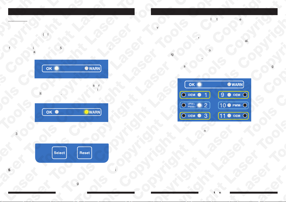
OK green LED will illuminate when everything is OK (no short, no reverse polarity,
no constant voltage on pins 3, 8, 9, 11, 12, 13; voltage on pins 1, 2, 6, 7, 10, 14, 15
(whether constant voltage or pulse).
InstructionsInstructions
The 8611 OBD Breakout Box and Signal Detector is suitable for 12V and 24V
systems. When it is plugged into the vehicle’s OBD socket it will start to detect
the voltage of the system and any voltage on the pins. If voltage is present, the
respective LEDs will illuminate as follows:
Protocol / pin indicator LED 2, 6, 7, 10, 14, 15:
GREEN: Indicates normal protocol communication (pulse) signal.
RED: Indicates constant voltage present.
Depending on the communication protocols:
Pin 6: CAN High; Pin 14 CAN Low
Pin 2: VPW+PWM+; Pin 10: PWM-
Pin 7: K-Line; Pin 15: L-Line
(When signal voltage is detected the green LED will flash accordingly; if the voltage
on the pins is constant, the LED will stay on and turn red.)
WARNING yellow LED will illuminate if there is constant voltage on pin 3, 8, 9, 11,
12, 13 or CAN bus polarity error VCANH<VCANL.
Select button is used to select pin for testing for voltage present. Pressing the
Select button, the pin number will switch to the next pin and display the voltage
value.
Reset button is to restore to the default setting where the pin selected is pin 16.
4
www.lasertools.co.uk
Example: Pin 2 has a pulse signal and the green LED flashes.
www.lasertools.co.uk
5
Page 4
Instructions
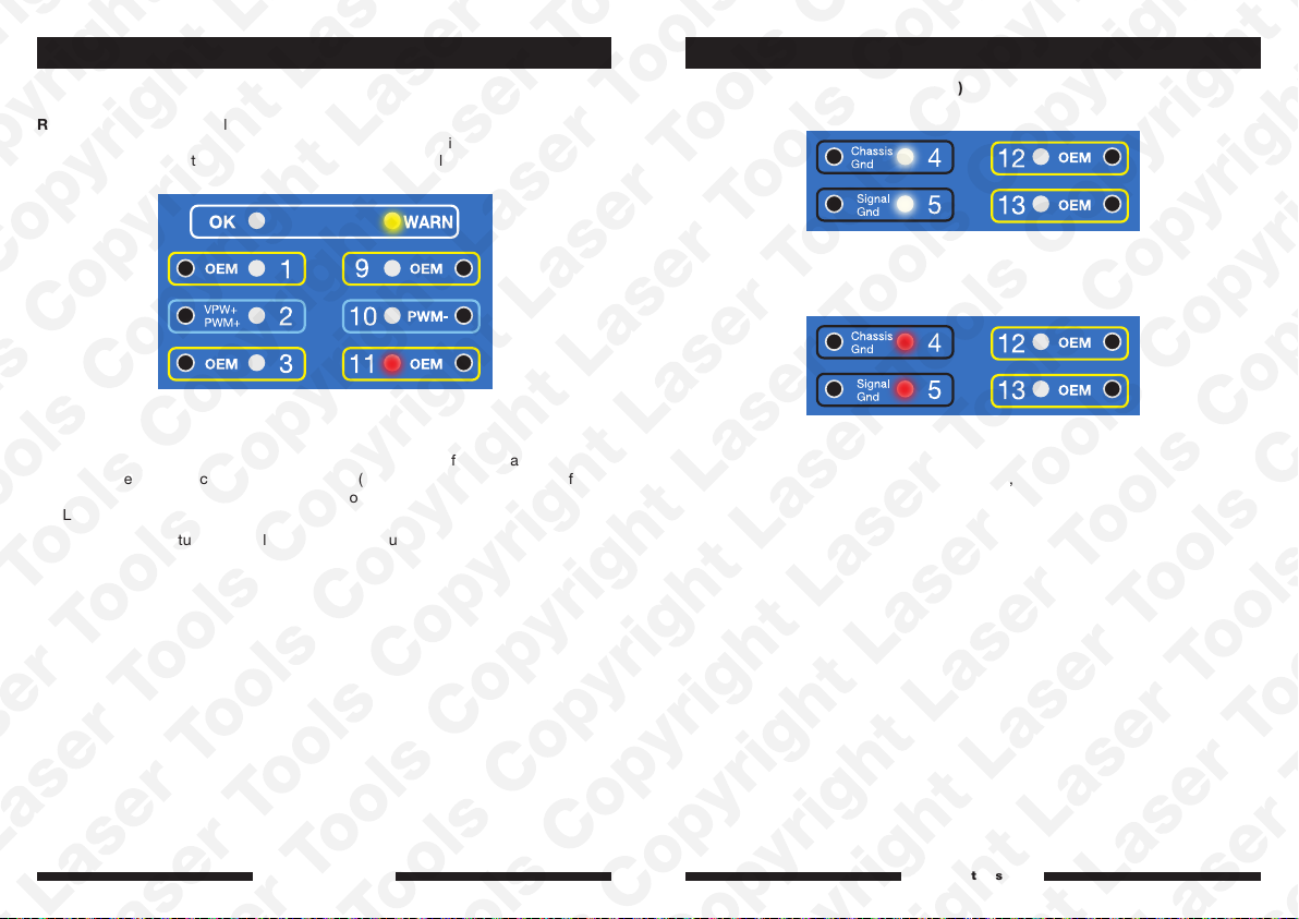
OEM-defined communication pin indicator LED 1, 3, 8, 9, 11, 12, 13:
YELLOW: Indicates normal protocol communication (pulse) signal.
RED: Indicates constant voltage present.
(If pulse voltage is detected on pins 1, 3, 8, 9, 11, 12, 13, their respective LEDs
flicker yellow; if the voltage on the pins is constant, LED will remain red.)
Instructions
Pin 4 & Pin 5 (chassis & signal ground):
GREEN: Correct ground.
Example: Pin 11 has a constant voltage signal — the red LED is always on.
Note: Different OEM (manufacturers) use many of these pins for special purposes
other than the communication protocol signals (for example, Nissan use pin 8 for
ignition voltage). If the breakout box detects constant 12V present on these pins,
the LED will stay on and become red.
Note: Due to the fluctuation of voltage readings in pulse voltage, the unit only
displays the peak-to-peak voltage (VPP) of the pulse.
6
www.lasertools.co.uk
RED: Reverse polarity detected.
With correct polarity pin 16 will illuminate green, if reverse polarity is detected, pin
16 will not be illuminated.
www.lasertools.co.uk
7
Page 5

Precautions
• When using the tester, please observe all normal safety precautions concerning
protection against the dangers of electrical current.
• Never apply voltage or current to the tester that exceeds the specified maximum
as shown in the specification above.
• Observe standard workshop safety procedures when using the tester.
• Do not let the tester get wet or use in damp or wet conditions.
• Keep the tester clean (use a damp cloth with pH-neutral detergent) and store in a
dry place with no extremes of temperature and humidity.
• Dispose of device according to relevant local authority guidelines.
Our products are designed to be used correctly and with care for the purpose
for which they are intended. No liability is accepted by the Tool Connection for
incorrect use of any of our products, and the Tool Connection cannot be held
responsible for any damage to personnel, property or equipment when using the
tools. Incorrect use will also invalidate the warranty.
If applicable, the applications database and any instructional information provided
has been designed to offer general guidance for a particular tool’s use and while
all attention is given to the accuracy of the data no project should be attempted
without referring first to the manufacturer’s technical documentation (workshop or
instruction manual) or the use of a recognised authority such as Autodata.
It is our policy to continually improve our products and thus we reserve the right to
alter specifications and components without prior notice. It is the responsibility of
the user to ensure the suitability of the tools and information prior to their use.
www.lasertools.co.uk
8611_Instructions_V3
 Loading...