

Page 1
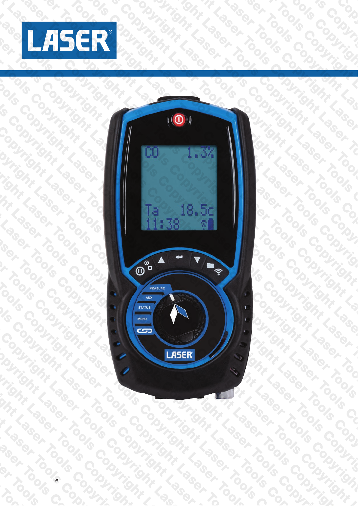
Laser EGA Series
8559 Digital CO Meter
Handheld Exhaust Gas Analyser
Stock No: MAN8559 Rev: 1.00123
© Tool Connection Ltd
January 2023
Page 2

CONTENTS
Page No.
Laser EGA OVERVIEW 4
ANALYSER FEATURES AND KEYPAD 5-8
KEYPAD BUTTONS 6
ANALYSER LAYOUT 7
BACK OF ANALYSER - PROBE ETC 8
BATTERIES 9
BATTERY TYPE 9
REPLACING BATTERIES 9
TIME AND DATE 9
CHARGING NIMH BATTERIES 9
BATTERY DISPOSAL 9
GENERAL SAFETY 10
FIRST TIME USE 11
GENERAL OPERATING PRINCIPLE 11-15
QUICK START 11
USER INTERFACE 11
STATUS 12
STATUS BAR 12
STATUS BAR LAYOUT 13
STATUS BAR MESSAGE AREA 14
STATUS BAR ICONS 14
STATUS BAR ICONS LEVEL 14
STATUS BAR MENU OPTIONS 15
STANDARD OPTIONS 15
USING MENU 15
MENU ITEMS 15
MEASURING EXHAUST GASES 17
2 Laser EGA SERIES MANUAL
Page 3

CO SENSOR PROTECTION PUMP OPERATION 18
AUX SCREEN 18
EDITING AUX SCREEN 18
MEASURE SCREEN 18
STORED MEMORY LOGS 19
MENU OPTIONS 19
VIEWING STORED LOGS 20
LOG VIEW MENU OPTIONS 20
FINDING STORED REPORTS 20
REPORT MENU OPTIONS 21
PRINTING 21
Laser INFRARED PRINTER 21
PRINTOUTS 22
Laser LINK 23
SPECIFICATIONS 24
EU DECLARATION 25
SERVICE - CALIBRATE - RECERTIFY 26
KANE ASSET MANAGER (KAM) 27-29
COLD WEATHER PRECAUTIONS 30
Laser EGA SERIES MANUAL 3
Page 4

Laser EGA OVERVIEW
Your Laser exhaust gas analyser has the ability to measure up to 3
dierent gases,
Depending on your options it measures or calculates:
● Carbon Monoxide 0-10,000ppm (CO) if tted
● Carbon Monoxide 0-10% (CO) if tted
● Carbon Dioxide (CO2) if tted
● Nitric Oxide (NO)
● Nitrogen Oxide (NOx)
● Corrected Carbon Monoxide (COk)
Your Laser EGA has a protective rubber cover with magnets for
“hands-free” operation and is supplied with an exhaust probe and
battery charger with 3 NiMH batteries.
Your Laser EGA has a large 6 line display showing data and test results
based on your actions. The display bottom line also highlights analyser
status at all times.
Your Laser EGA prints test reports using an optional infrared printer.
Your Laser EGA stores up to 45 logs.
You can enter 2 lines of 24 characters on your test results printout.
Laser LINK wirelessly connects optional Laser LINK devices to your
analyser.
4 Laser EGA SERIES MANUAL
Page 5
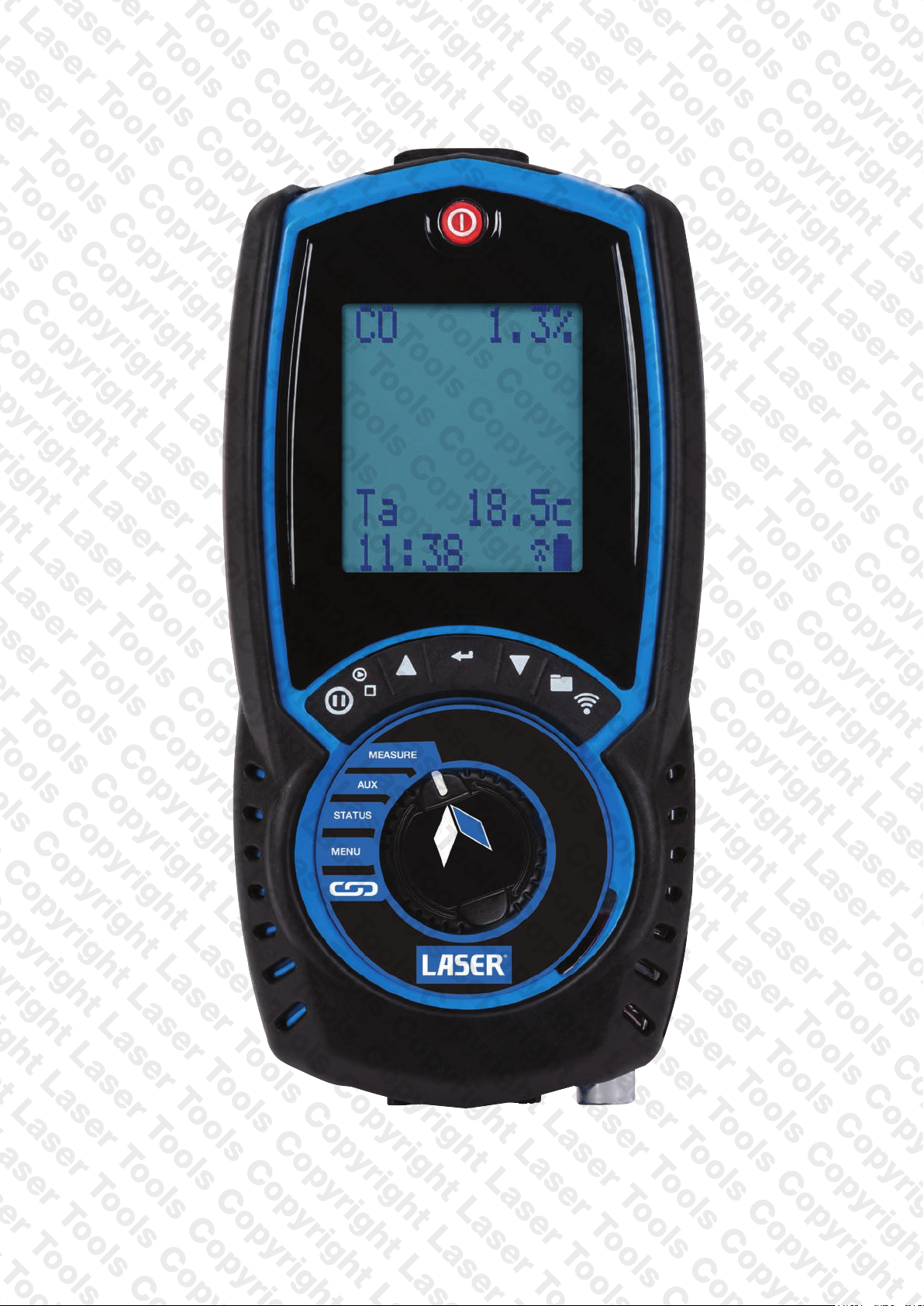
ANALYSER FEATURES AND KEYPAD
Laser EGA SERIES MANUAL 5
Page 6
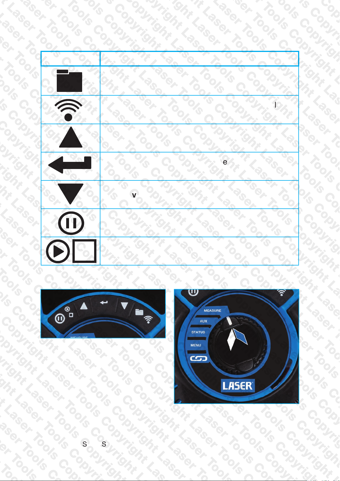
KEYPAD BUTTONS
ICON DESCRIPTION
Print report - Short press to print a report - Analyser
offers a destination choice when wireless and irda tted
Enter key - Used to select the current option
- also selects torch in some dial positions
Navigate down - Short press to scroll down
Save log - Long press to store data
Navigate up - Short press to scroll up
Data hold - Short press to hold current data on screen
Function keys
(see status bar section)
Pump toggle - long press to toggle
the pump on and off
6 Laser EGA SERIES MANUAL
Rotary dial
Page 7
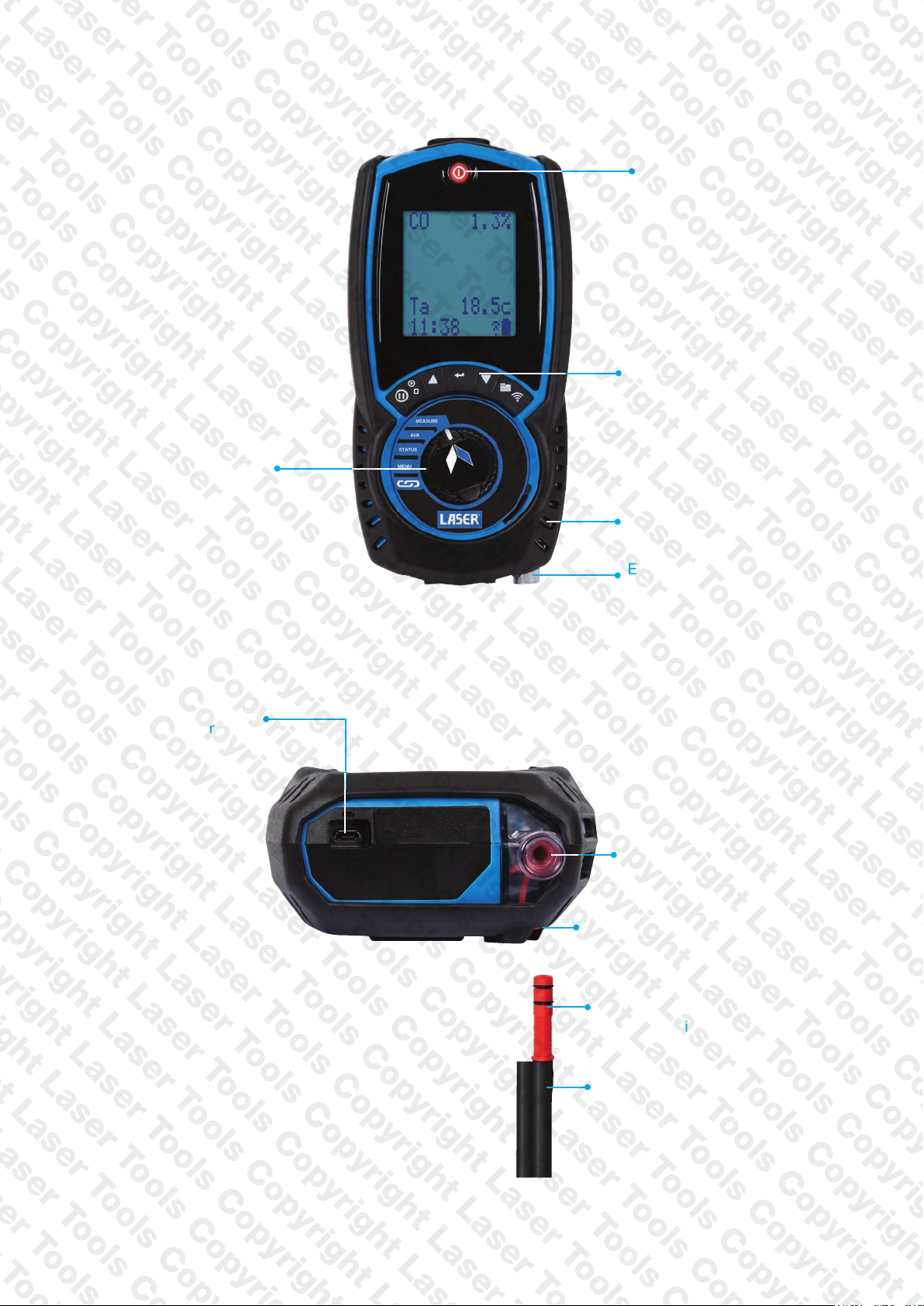
ANALYSER LAYOUT
Rotary dial - Selects
• Menu
• Status
• Measure
On / Off
Function keys
(see page 6)
Water trap &
particle filter
Battery
charger
Exhaust gas
inlet
Exhaust gas
inlet
Watertrap drain with
red plug
Red connector
- plugs into
exhaust gas inlet
Exhaust probe hose
Laser EGA SERIES MANUAL 7
Page 8
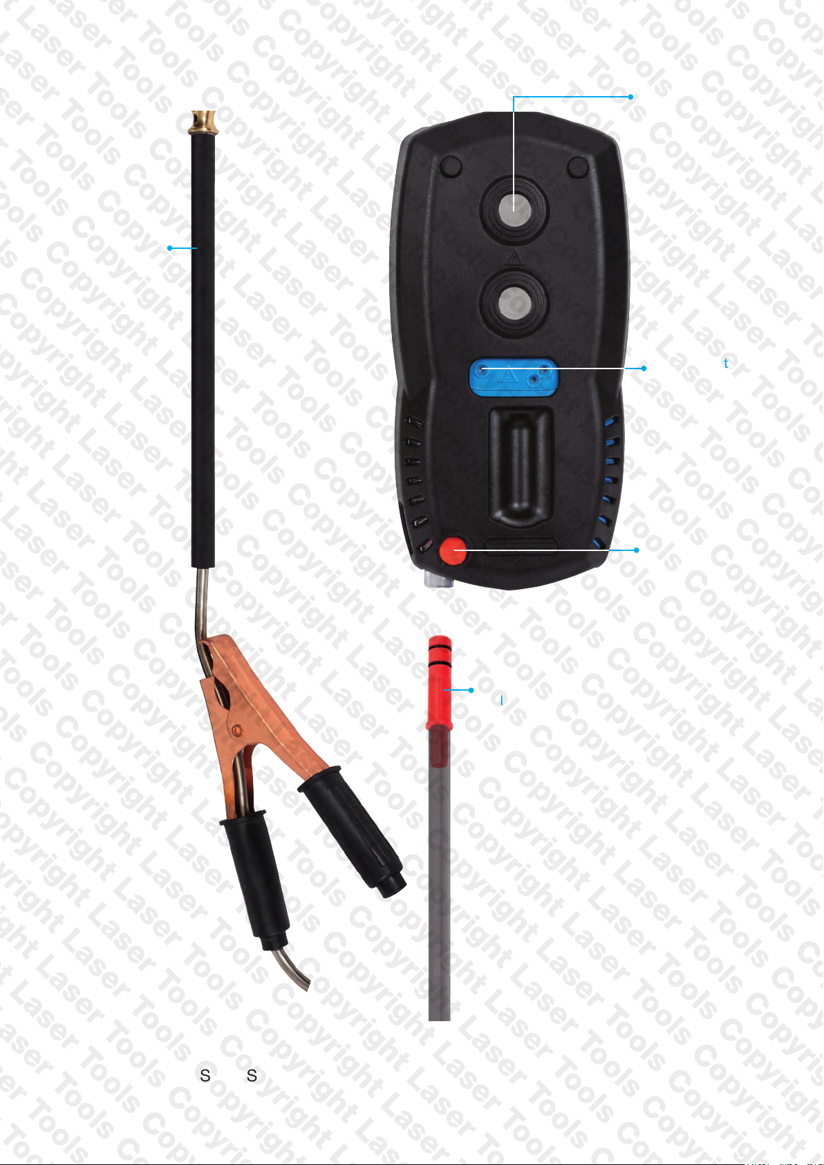
Exhaust
Probe
Magnets x2
Gas exhaust
(see page 10)
Red connector
- plugs into
exhaust gas inlet
Watertrap drain
with red plug
8 Laser EGA SERIES MANUAL
Page 9

BATTERIES
BATTERY TYPE
Your Laser EGA uses rechargeable Nickel Material Hydride (NiMH)
batteries - Using other battery types may void your analyser’s warranty.
WARNING
Although you can use Alkaline batteries you must not charge your
analyser with Alkaline batteries tted.
Do not mix NiMH cells with dierent capacities or from dierent
manufacturers - All batteries must be identical.
REPLACING BATTERIES
Turn over your analyser, remove protective rubber cover, nd battery
compartment & t 3 NiMH “AA” rechargeable batteries ensuring correct
battery polarity. Replace battery cover & protective rubber cover.
TIME AND DATE
After changing batteries reset your analyser time & date.
CHARGING NiMH BATTERIES
Your Laser EGA uses a standard Micro USB connector - For best results
turn o then connect your charger. Charging indicator will illuminate then
turn o when charging is complete.
Your rst charge should be for 8 hours - Thereafter NiMH batteries can
be topped up at any time, even for short periods
If your batteries discharge and your analyser enters a low power
shutdown, 1 hour charge provides approx. 2 hours continuous use.
BATTERY DISPOSAL
Always dispose of depleted batteries using approved disposal methods
to protect our environment.
Laser EGA SERIES MANUAL 9
Page 10
GENERAL SAFETY
SAFETY WARNING
Your analyser extracts combustion gases that may be toxic in relativity
low concentrations. These gases are exhausted from the back of the
analyser. This analyser must only be used in well-ventilated locations
by trained and competent persons after due consideration of all the
potential hazards.
Portable gas detectors should conduct “bump” tests before relying
on units to verify atmospheres are free from hazards.
A “bump” test is a way to check an instrument works within acceptable
limits by briey exposing it to known gas mixtures to change the output
of all sensors present.
NOTE: This is dierent from a calibration where your analyser is
exposed to known gas mixtures but allowed to settle to a steady
gure with readings adjusted to the stated gas concentration of the
test gas.
Protection Against Electric Shock
(In accordance with EN 61010-1:2010):
This analyser is designed as Class III equipment and should only be
connected to SELV circuits. The battery charger is designated as:
● Class II equipment
● Installation category II
● Pollution degree 2
● Indoor use only
● Altitude to 2000m
● Ambient temperature 0°C-40°C
● Maximum relative humidity 80% for temperatures up to 31°C
decreasing linearly to 50%RH at 40°C
● Mains supply uctuations not to exceed 10% of the nominal voltage
10 Laser EGA SERIES MANUAL
Page 11
FIRST TIME USE
Charge your analyser batteries for 8 hours - an overnight charge should
be sucient for an average 8 hour day.
Take time to read this manual fully and be aware your analyser
conguration may not support all features explained in this manual.
Before using your analyser ensure it is set up for your requirements.
NOTE: Your analyser STATUS bar displays current time, date and
battery status - Check time & date are correct as they can only
be changed if you have not stored logs in Memory to protect the
integrity of your stored data.
GENERAL OPERATING PRINCIPLE
Using your Laser EGA is simple with the rotary dial and user interface.
Most tests can be made with little user activity.
Your analyser status bar oers options based on tasks you are
performing and displays useful information and messages.
QUICK START
Turn on your analyser in fresh outdoor air pressing the button for
2 seconds. Your analyser starts a 60 second zero calibration - once
completed select your tests by turning the analyser rotary dial.
USER INTERFACE
Your analyser display shows 5 lines of tests & a status bar. The backlight
activates each button press then turns o after 10 seconds.
Navigate through your options and menu choices via 3 dedicated
& buttons.
Button presses are either short or long.
Laser EGA SERIES MANUAL 11
Page 12
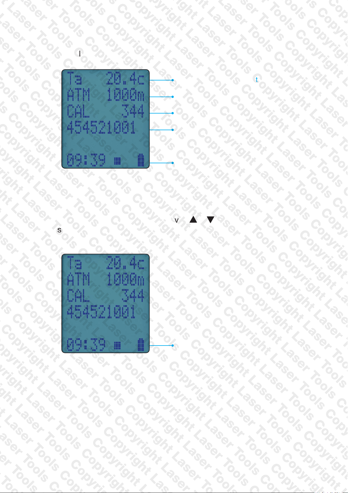
STATUS
Rotate dial to “Status” :
Current ambient temperature
Current atmosphereic pressure (mbar)
No. of days until next calibration due
Serial number
Status bar
STATUS BAR
Status bar shows analyser status and oers options based on your
settings.
Navigate through status bar options via
bar is on display.
Status bar
& buttons when status
12 Laser EGA SERIES MANUAL
Page 13
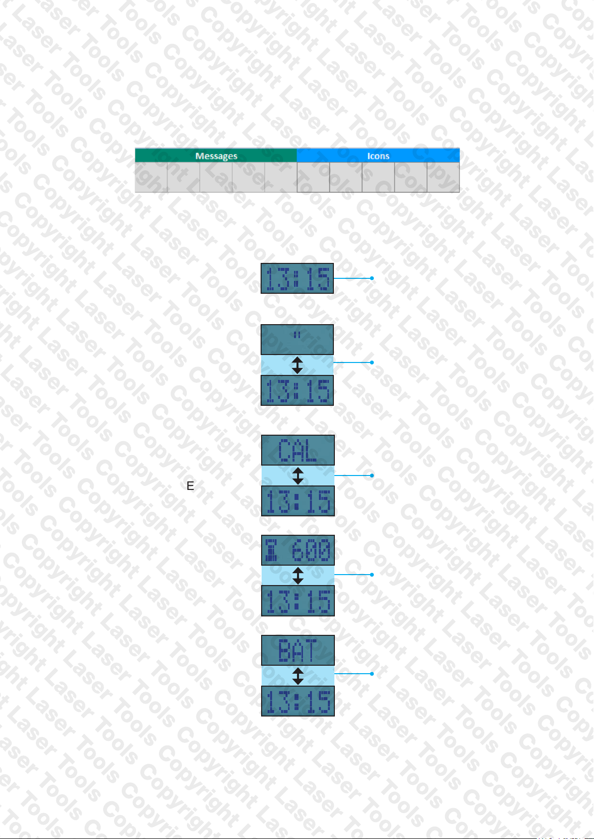
STATUS BAR LAYOUT
Status bar splits into 2 zones, Message & Icons shown below:
STATUS BAR MESSAGE AREA
CLOCK FUNCTION
DATA HOLD
FUNCTION
CALIBRATION DUE
WARNING MESSAGE
AIR PURGE
“SNOOZE” TIMER
Displays current time
Display alternates
between hold symbol &
Time stamp of held data
Display alternates
between calibration due
and current time
Display alternates air
purge delay symbol &
Current time
LOW BATTERY
WARNING MESSAGE
Display alternates
between BAT symbol &
Current time
Laser EGA SERIES MANUAL 13
Page 14
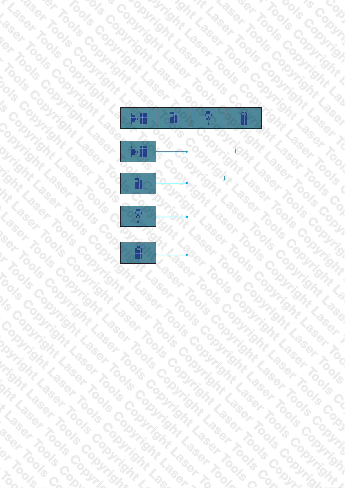
STATUS BAR ICONS
Icons give quick and simple status information:
STATUS BAR ICON LEVEL
ICON LIST
PUMP
LOGGED DATA
SENDING DATA
BATTERY
Pump status indication
(Running/Stopped)
Indicates the analyser
contains logged data
Indicates data is being transmitted
to either the App or the Printer
Battery Status indication
14 Laser EGA SERIES MANUAL
Page 15
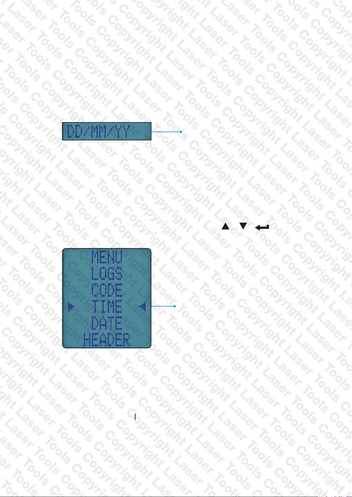
STATUS BAR MENU OPTIONS
Status Bar offers you contextual menu items based on your screen
display.
STANDARD OPTIONS
Battery Status indication
USING THE MENU
Rotate dial to MENU to customise your analyser default setting to your
requirements.
Navigate through the MENU using these buttons &
Menu option to edit
As you navigate up or down items will move up or down the screen
returningto the beginning.
Note: To exit MENU turn your analyser rotary dial to any position - note
any unsaved changes will be lost.
Laser EGA SERIES MANUAL 15
Page 16
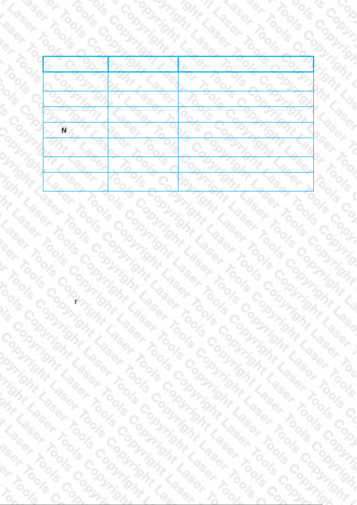
MENU ITEMS
MENU ITEM MENU TEXT OPTIONS/COMMENTS
TIME TIME
DATE DATE DD/MM/YY format
HEADER HEADER Edit the 2 Line Header on your printouts.
PRINTER TYPE IR PRINT Select, KMIRP, IRP-3
LOGS LOGS
LANGUAGE LANGUAGE Select required language from the list.
CODE CODE
E.G. 7am = 07:00:00, 7pm = 19:00:00
Password protected for authorised
service agents only - Default to 000000
HH:MM:SS format
View current memory usage
& stored logs
Laser LINK
This unique feature provides future connectivity to a selection of
peripheral devices currently under development, which will link wirelessly
to your analyser, and utilise its display functionality. Once connected,
they will remain connected unless specically dis-connected.
Keep in touch with Laser via www.lasertools.co.uk
16 Laser EGA SERIES MANUAL
Page 17
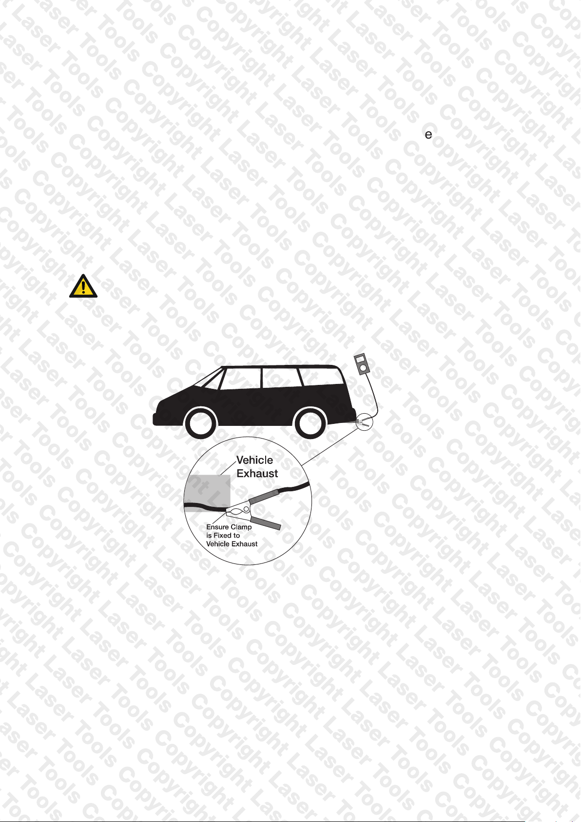
MEASURING EXHAUST GASES
After countdown is nished and your analyser is ready to use, put your
exhaust probe into the vehicles exhaust.
For normal emission testing, ensure that the engine has been preconditioned to normal operating temperature. The engine conditions
must be constant and stable to give a stable measurement.
Ensure the probe is fully inserted into the exhaust pipe to avoid any
dilution of the exhaust gas with back-ushing ambient air. Position the
hose assembly away from any hot surfaces.
SAFETY WARNING
Use suitable protection when disconnecting the probe, as it may be hot!
Do not exceed analyser operating specications - In particular:
● Do not exceed analyser internal temperature operating range
● Do not put analyser on hot surfaces
● Do not exceed analyser water trap max levels
● Do not let analyser particle lter become dirty and blocked
Check readings are stable and within expected range.
Laser EGA SERIES MANUAL 17
Page 18
CO SENSOR PROTECTION PUMP OPERATION
Your analyser CO sensor is automatically protected from high levels of
CO. When CO is above the maximum range of your analyser the main
pump stops and CO Purge pump starts.
Your analyser displays - - - - until CO levels fall below the maximum
measurement range.
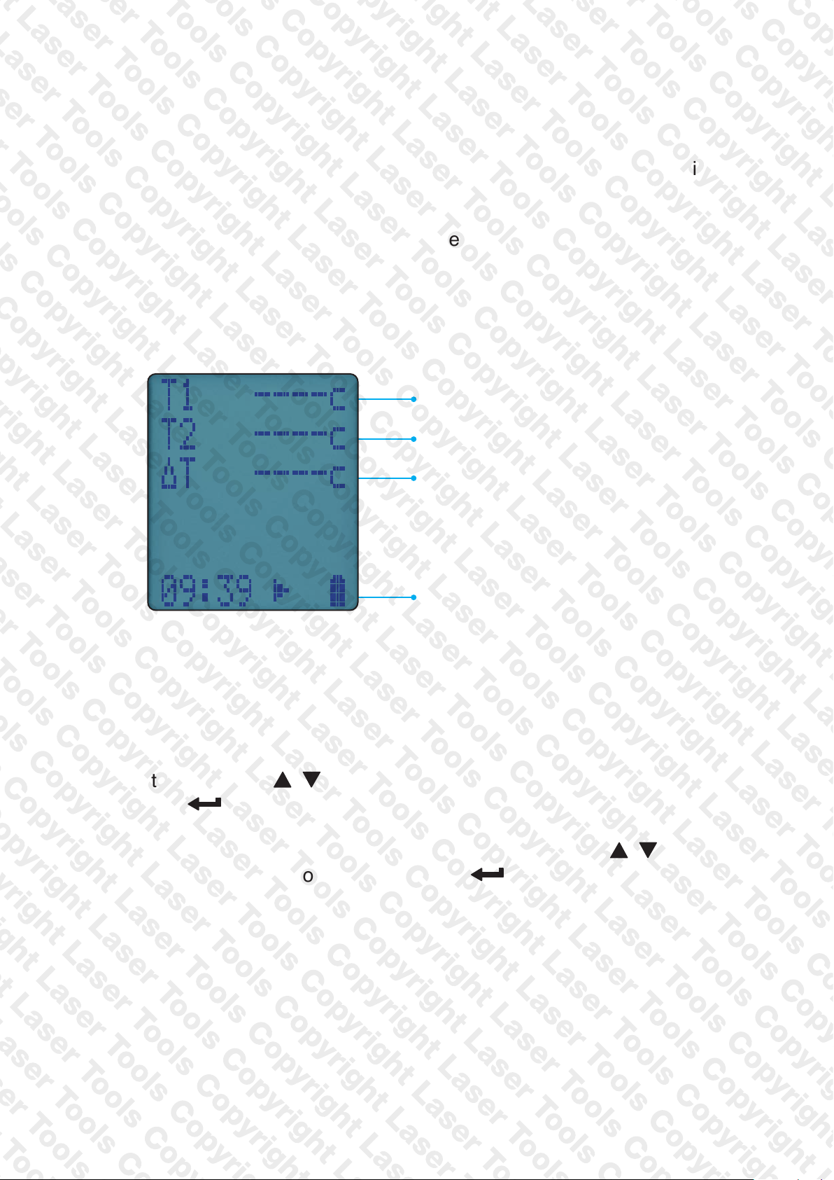
AUX SCREEN
Line 1
Line 2
Line 3
Status bar
EDITING AUX SCREEN
You can customise lines 1 to 5 of your analyser AUX screen.
To edit a line, press until EDIT appears on the status bar. Press
and hold to select EDIT.
Cursor ashes and line number appears in status bar. Use to
select option to appear on line then press to enter option.
18 Laser EGA SERIES MANUAL
Page 19
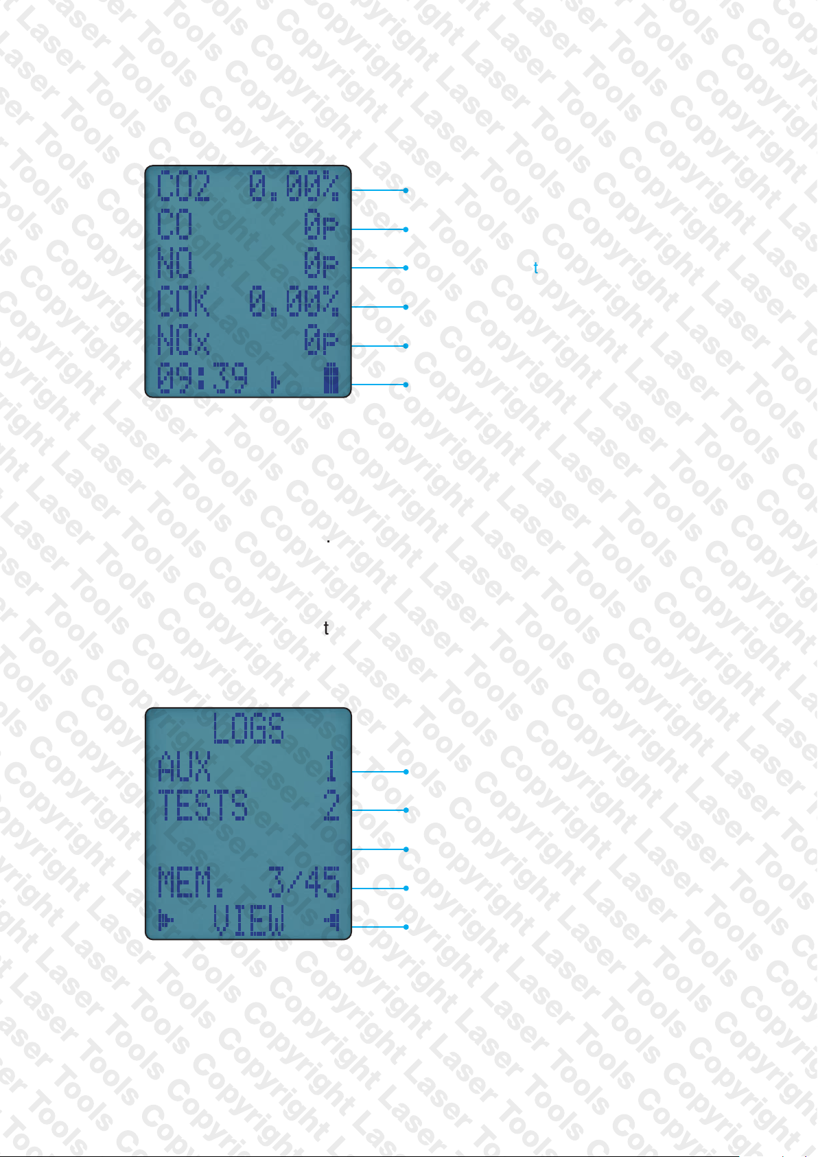
MEASURE SCREEN (Depending on sensors tted)
2 reading
CO
CO reading
NO reading (if tted)
COK reading
NOx reading (if tted)
Status bar
STORED MEMORY REPORTS
Your Laser EGA utilises a shared memory system which means stored
logs are not limited by type.
An icon displays when your analyser has stored data.
To view current memory rotate dial to MENU then select LOGS to display.
No. of stored Auxiliary logs
No. of stored EGA logs
Total memory used
Menu options
Laser EGA SERIES MANUAL 19
Page 20
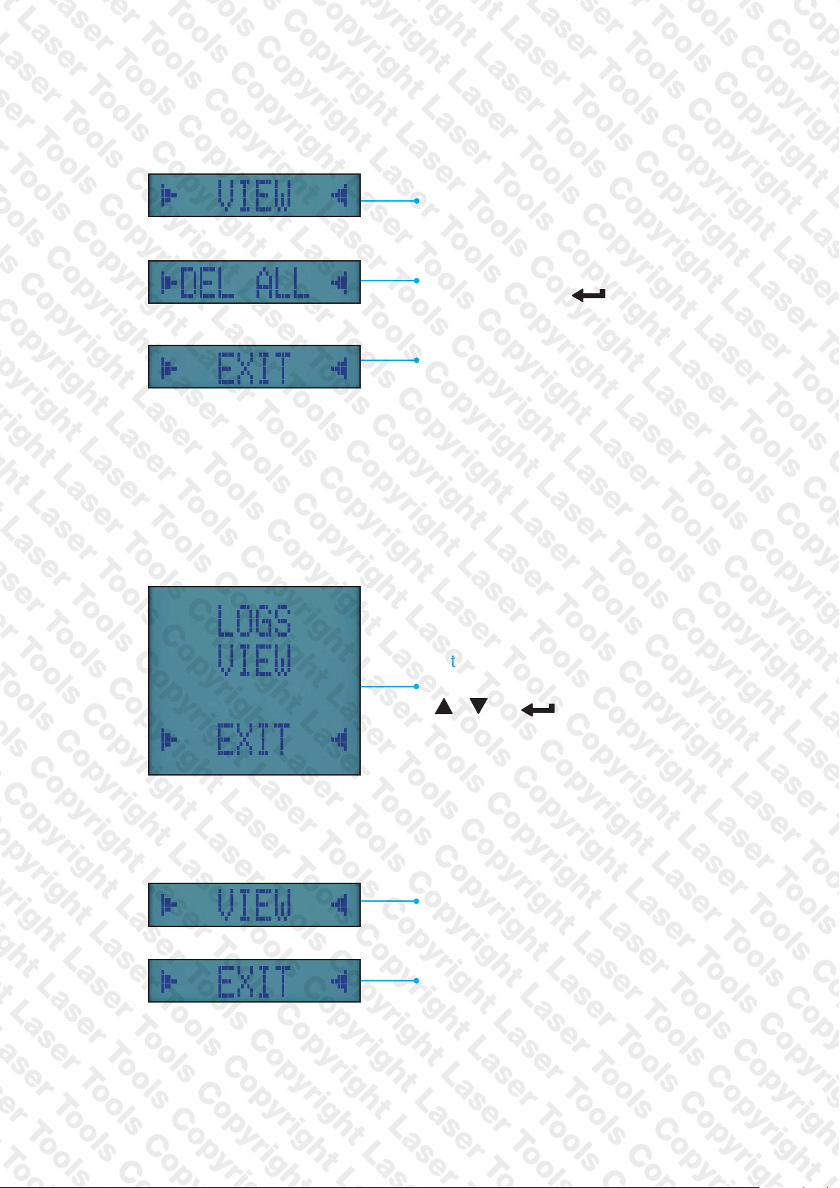
MENU OPTIONS
VIEWING STORED REPORTS
View stored reports if available - enter
sensory menu to select report type
Delete all sorted reports if available - to
delete long press
Return to main menu
button
To view your reports, select VIEW option from LOGS Menu:
List of available LOGS
To navigate and select use
&
REPORT VIEW MENU OPTIONS
View stored Tests
20 Laser EGA SERIES MANUAL
Returns to previous menu
Page 21
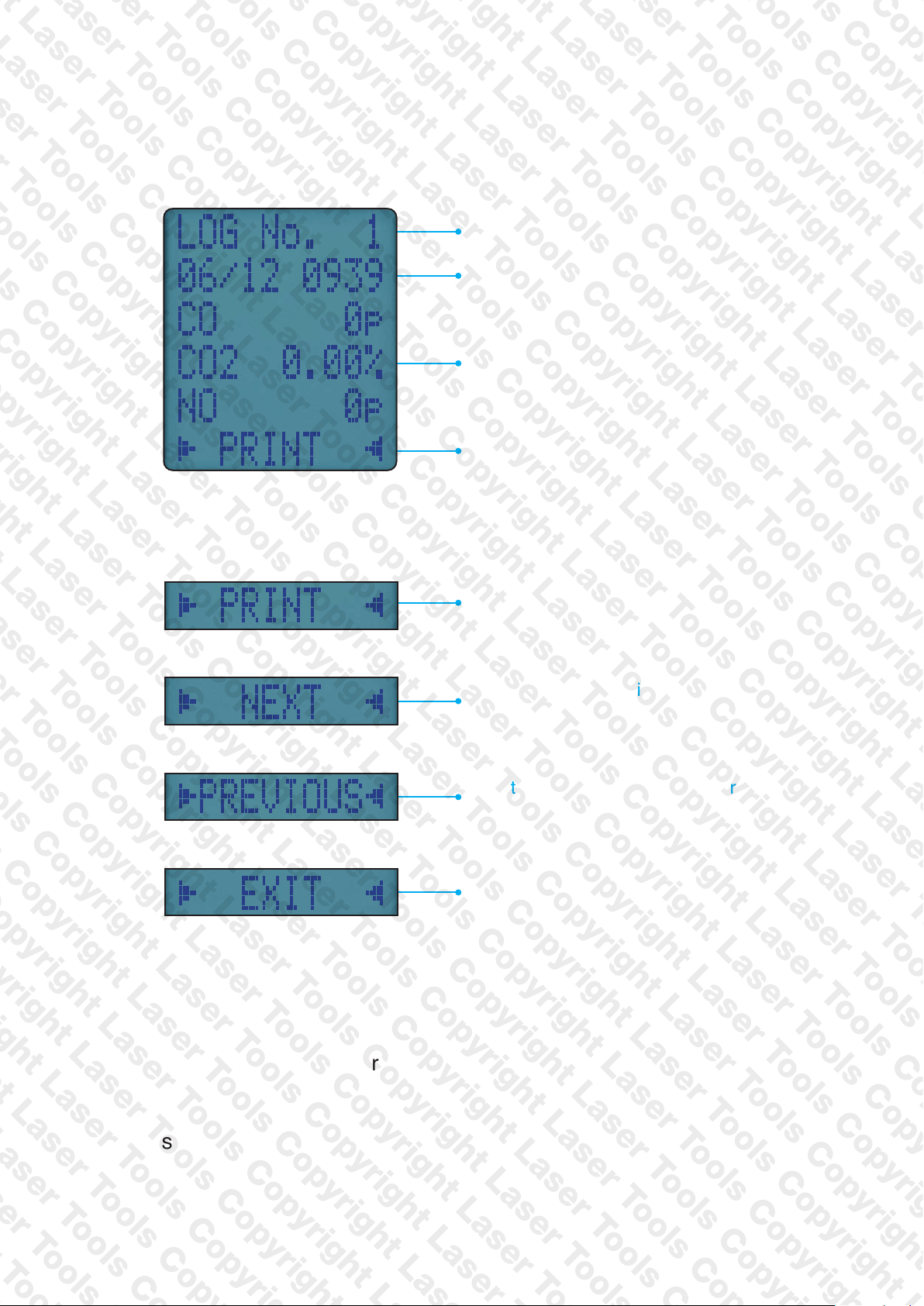
FINDING STORED REPORTS
Once you select your report type the rst stored log is displayed:
LOG Number of that type
Time and date of LOG
Report readings specic to report type
Navigation menu options
REPORT MENU OPTIONS
Print currently selected report
Use to nd next available report if
available
Use to nd previously selected report
once navigation begins
Return to main menu
INFRARED PRINTER
The Laser 8559 is compatible with Infra-Red printer IRP3, which is
available as an optional extra
To use your printer, switch on and place the printer infrared receiver in
line with the emitter on top of your analyser - allow a 15cm gap between
analyser and printer. Press and hold button for 2 seconds to log a
pressure and temperature report - See PRINTING to print stored reports.
Laser EGA SERIES MANUAL 21
Page 22
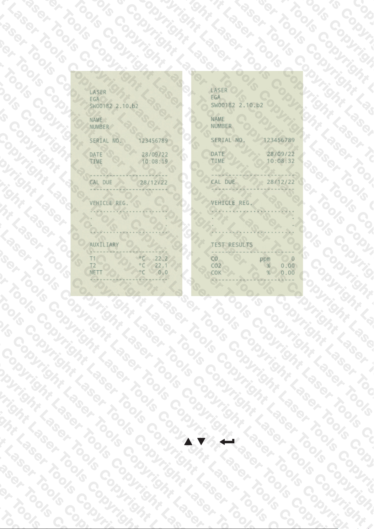
PRINTOUTS
TestsAux
Laser LINK WIRELESS MEASUREMENT AND DATA
TRANSFER – for use with future peripheral devices
You can wirelessly connect optional Laser LINK devices to your analyser.
Rotate dial to Laser LINK on your analyser to manage how your analyser
communicates with wireless devices.
To ADD, REMOVE and check STATUS of optional Laser LINK devices
(when available ) select LINK using
22 Laser EGA SERIES MANUAL
& buttons.
Page 23

SPECIFICATIONS
PARAMETER RANGE RESOLUTION ACCURACY
Temperature Measurement
Inlet temperature
(Internal Sensor)
Exhaust Gas Measurement
Carbon Monoxide 0 - 10,000ppm 1ppm
Carbon Monoxide 0-10.0% 0.01% ±5% reading 0.1%-10.0%
0.50°C 0.1°C ±1°C
±5ppm < 100ppm
±20ppm < 400ppm
±5% > 400ppm - 2000ppm
±10% > 2000ppm–
10,000ppm
Carbon Dioxide 0-20% 0.1%
Nitric Oxide (if tted) 0 - 600ppm 1ppm
Calculations
Corrected Carbon Monoxide 0 - 21% 0.1% ±0.3% Volume
Pre-programmed Emissions
Battery Life >8 hours (continuous with pump on)
Certication
Operating Conditions
Temperatures 0 - 45°C
Humidity 15 to 90% RH, (non-condensing)
Power Supply Rechargeable batteries, USB Charging
Laser-EGA is independently tested and certied to EN50379,
Parts 1-3
±0.3% Volume
±5ppm or ±5% of reading
(whichever is greater)
Physical Characteristics
Weight Approx. 0.625g
Dimensions 216mm x 105mm x 45mm
Laser EGA SERIES MANUAL 23
Page 24

EU Directive
UK Directive
EMC - 2014/30/EU
EMC Regulations 2016
EN50270:2015
RoHS – 2011/65/EU
RoHS 2012
IEC62321-1:2013; IEC62321-2:2013;
2:2017
LVD – 2014/35/EU
Electrical Equipment
2016
EN61010-1:2010
CERTIFICATE OF CONFORMITY
As the manufacturer/ importer/ distributor of our
product;
8559
Digital CO meter
We confirm that the product has been tested and approved for
conformance against the following directives / standard;
IEC62321-3-1:2013; IEC62321-4:2013;
IEC62321-5:2013; IEC62321-6:2015;
IEC62321-7-1:2015; IEC62321-7-
(Safety) Regulations
SIGNED:
Mr Eddie Altham, Managing Director
DATE: 1ST DEC 2022
24 Laser EGA SERIES MANUAL
Page 25

SERVICE - CALIBRATION - UPGRADES
Our International Service Partner for the Laser range of EGA’s, is :
Kane International Ltd
Kane House, 11 Bessemer Road
Welwyn Garden City
Hertfordshire
AL7 1GF,
UK
t: 0800 059 0800
e: [email protected]
From outside UK Call +44 1707 375550
Laser recommends that all gas analysers & pressure meters should be
serviced and calibrated annually.
Your Laser Gas Analyser comes as standard with a 12 month
manufacturing warranty. You can extend your Laser analyser and
pressure meter’s ‘no quibble’ warranty, up to 10 years by returning
your analyser & pressure meter via the Kane KAM dashboard annually.
You should therefore, ensure you register your Laser Gas Analyser for
annular service within the rst 12 months of ownership. The following
pages ( pp27 – 30 ) describe the Kane KAM procedure for returning your
Laser Gas Analyser securely.
Please register for this service by visiting our Laser Tools web-site, and
follow the KAM service link on the 8559 Gas Analyser web-page.
All charges relating to Service, Calibration and Upgrades to your Laser
EGA, will be handled directly via the KAM dashboard.
Your Laser Gas Analyser will be returned following Service, Calibration,
or Upgrade, within 24 hours of it being received at the KAM Service
Centre.
Laser EGA SERIES MANUAL 25
Page 26
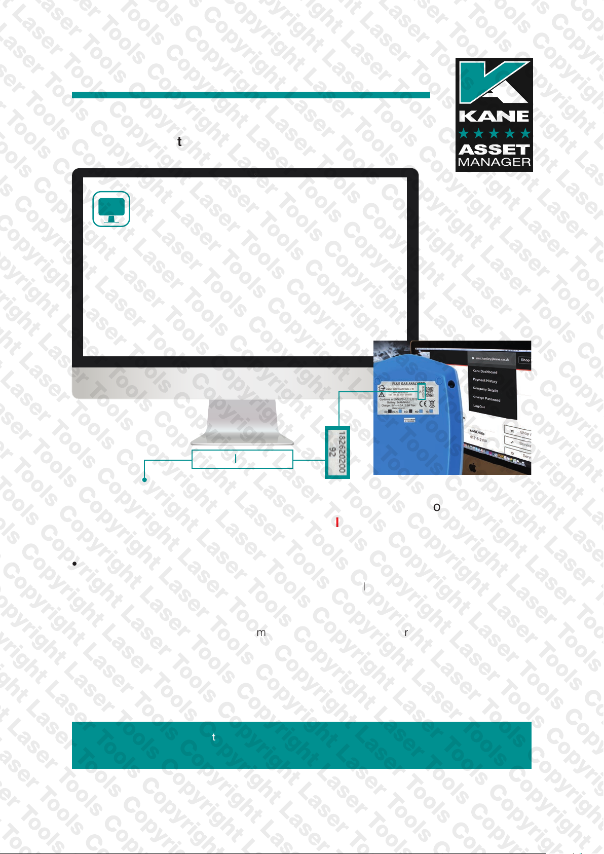
KANE ASSET MANAGER (KAM)
The fastest way to manage your analyser’s
recertification with FREE postage using www.kane.co.uk
KAM
Register your KANE analyser to
create your KAM dashboard:
★ Simple online booking on www.kane.co.uk
★ Relevant product specific promotions, special offers & discounts
★ Automatic reminder when due for recertification
★ FREE POSTAGE returning your KANE analyser
★ SAME DAY annual FGA recertification OR YOUR MONEY BACK*
*Excludes KANE '9 series' analysers & UKAS certificates
Use all 11 digits
Please register your analyser at www.kane.co.uk
& download the full instruction manual from your KAM dashboard
PLEASE READ ALL SAFETY WARNINGS IN THE MANUAL
Use your KAM dashboard to:
• View - your Payment History / Company Details / Analyser Details / Service Pricing
• Buy KANE products, accessories, spares & consumables with FREE delivery
• Manage your KANE analyser’s recertification online to receive same day turnaround
• Service History: Access, view & email electronic Calibration Certificates when required
for compliance
• Report Stolen: Reporting your analyser stolen ensures our Stolen Analyser Register is
up-dated & helps prevent industry colleagues unknowingly buying stolen goods
• Remove your KANE Analyser once sold so its new owner can also benefit
There are dierent KAM options & we'd be delighted to discuss your individual requirements
Contact: [email protected]
26 Laser EGA SERIES MANUAL
Page 27
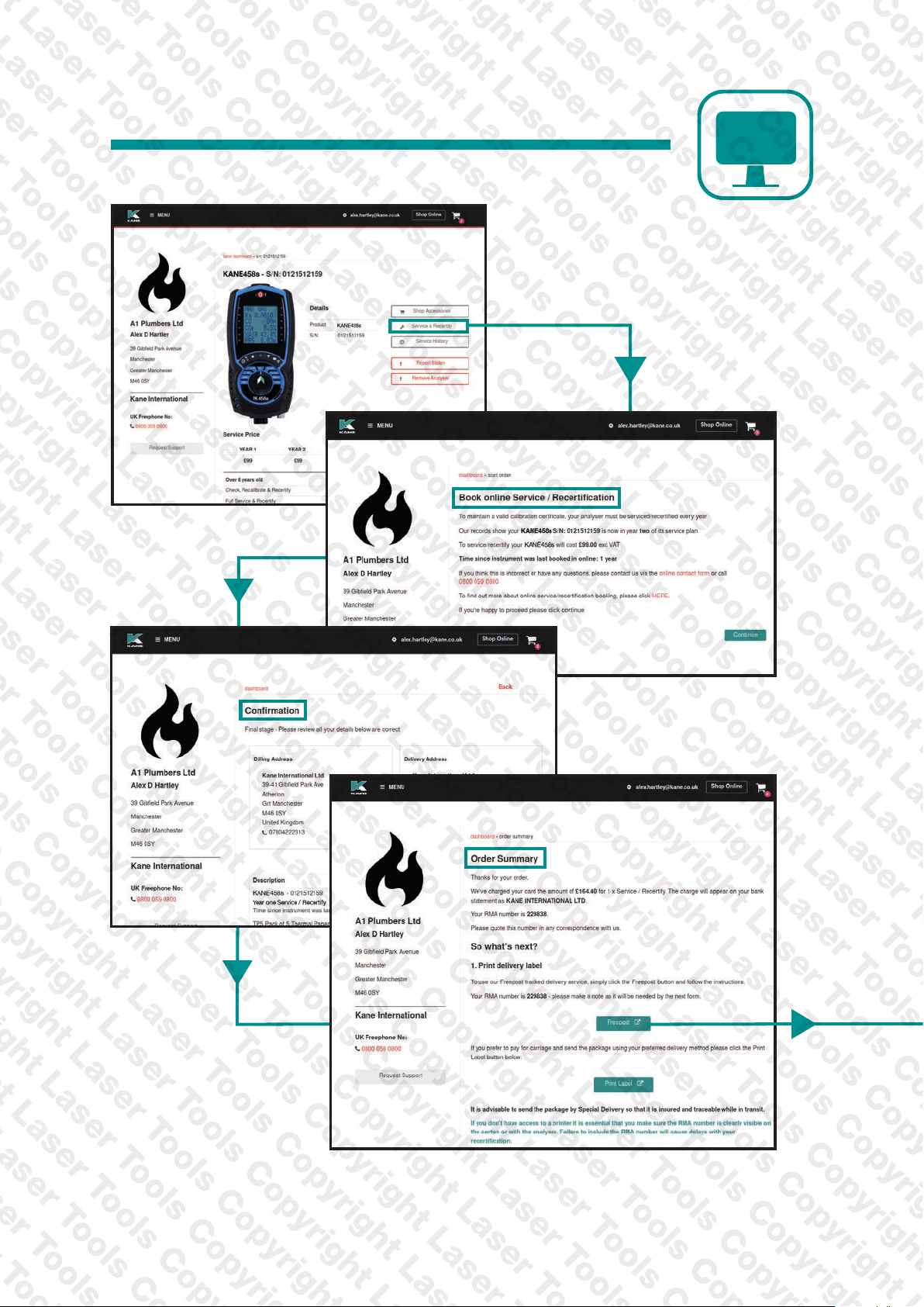
Your support - our way
KAM
Laser EGA SERIES MANUAL 27
Page 28
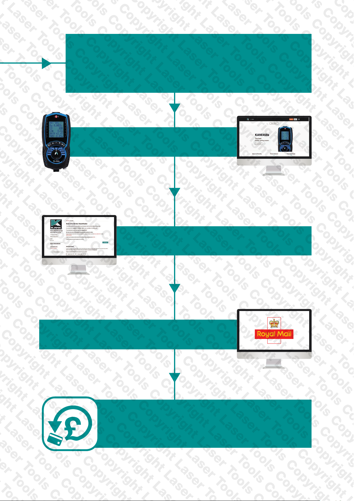
GUARANTEED
SAME DAY DESPATCH
Analyser Service & Recertication
Register your analyser on
www.kane.co.uk
Book & pay to Service & Recertify
via your KAM dashboard
Select FREEPOST for tracked
carriage - UK mainland only
Your analyser will be despatched
on the same day we receive it...
OR YOUR MONEY BACK
28 Laser EGA SERIES MANUAL
*
Page 29

WHERE TO SEND YOUR ANALYSER
Kane International Ltd
Kane House, 11 Bessemer Road
Welwyn Garden City
Hertfordshire
AL7 1GF,
UK
t: 0800 059 0800
From outside UK Call +44 1707 375550
COLD WEATHER PRECAUTIONS
It is important you keep your analyser in a warm place overnight.
Electronic devices that become really cold, by being left in a vehicle
overnight, suffer when taken into a warm room the next morning.
Condensation may form affecting analyser performance.
Analyser electrochemical sensors are affected by condensation or water
being sucked into the analyser, stopping sensors seeing ue gas. When
this happens, oxygen or carbon dioxide readings will display as “-” &
sensors may be permanently damaged.
If you think your analyser is affected by condensation or water ingress,
leave the analyser running in a warm place with pump ‘ON’ sampling
fresh air for a few hours. Connect your mains adapter or battery charger
to avoid draining batteries.
If you still experience problems please contact Kane Customer Service.
Laser EGA SERIES MANUAL 29
Page 30

THIS PRODUCT CONFORMS WITH THE FOLLOWING
PLEASE RECYCLE
PACKAGING MADE IN THE UK
30 Laser EGA SERIES MANUAL
Page 31

Laser EGA SERIES MANUAL 31
Page 32

Thank you for buying this analyser.
Before use, please register on our website
www.lasertools.co.uk/product/8559
Or scan the QR code to go directly to
register your product online on the
KAM service dashboard
Tool Connection Ltd
Kineton Road
Southam
Warwickshire
CV47 0DR, UK
email:[email protected]
KAM telephone: 0800 059 0800
32 Laser EGA SERIES MANUAL
 Loading...