

Page 1
Part No. 8514
Instructions
Engine Timing Tool Master Kit
PSA Wet Belt 1.0, 1.2 Petrol
(with Pulley Holding Tool)
www.lasertools.co.uk
Page 2
The 8514 kit brings together the Laser 8570 engine timing kit and Laser 8369
crankshaft pulley holding tool and the newly introduced 8870 exhaust camshaft
alignment tool, for use on EB0 and EB2 wet belted engines from the PSA (Stellantis)
group, into one complete master kit.
It features all the tools that allow the most cost effective method of timing these
engines depending on the cam cover fitted (early EB2 engines have a one piece
cam cover that must be removed to access the cams; later engines have a split
plastic cam cover allowing a simpler method of timing to be used). The Laser 8570
kit provides the tools do the job in both ways allowing significant time saving to be
made on the later engines.
• Applications include: Citroën DS, Peugeot, Toyota & Vauxhall/Opel models.
• Engine Applications include: EB0 1.0L & EB2 1.2L 3 cylinder wet belted engines,
please see full applications list.
• Includes Laser Part No. 8369 crankshaft holding tool & Part No. 8870 camshaft
holding tool.
• Contains tools equivalent to: OEM refs. 0109-2A, EN-52127-1, 0109-2B, 0197-N,
EN-52127-2, J-0109-2C, J-0109-2D & 0109-2E.
Use in accordance with OEM instructions.
ComponentsIntroduction
www.lasertools.co.uk
OEM Ref.
Comp.
Ref.
Code
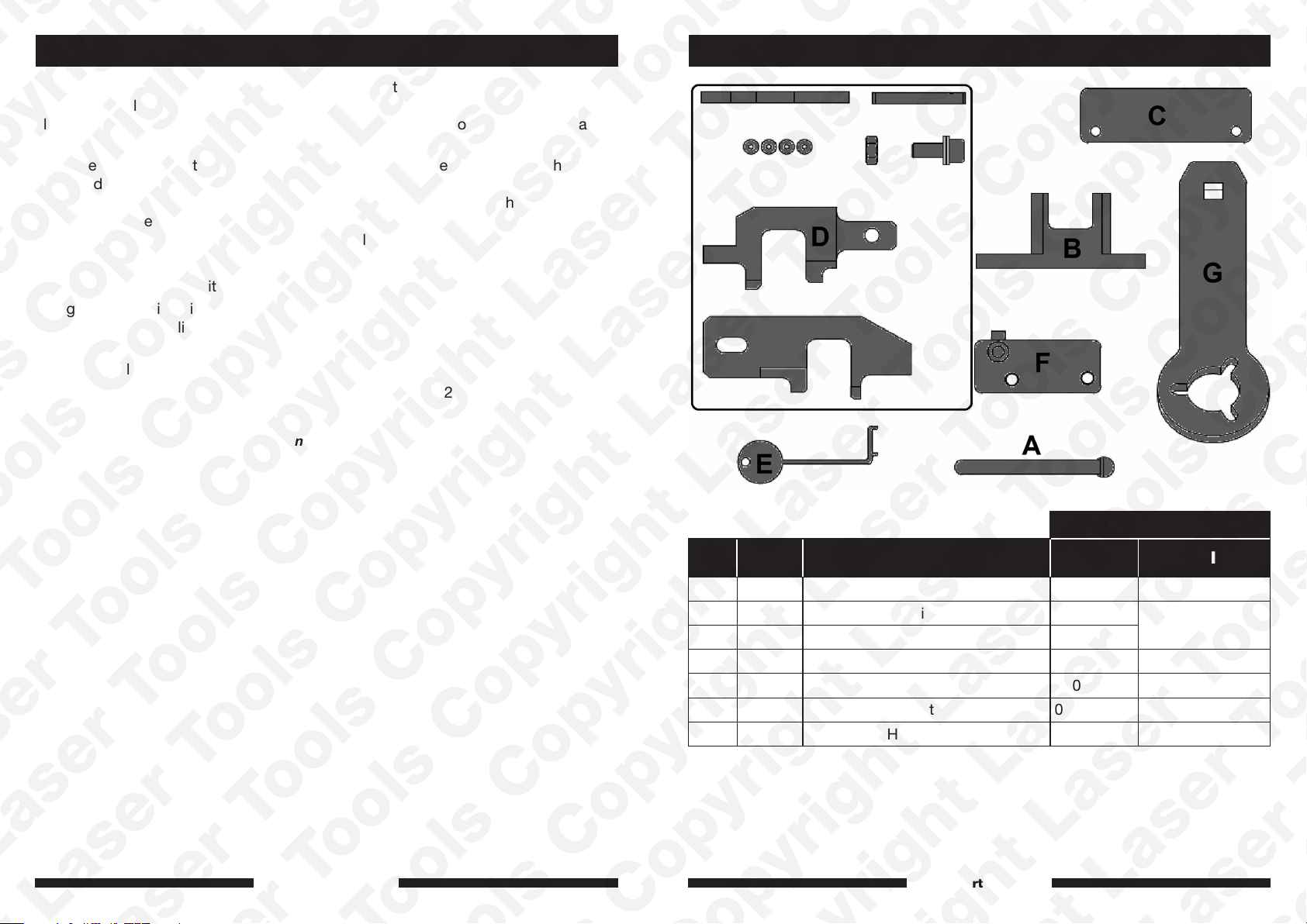
A C662 Flywheel Locking Tool 0109-2B EN-52127-2
B C994 Inlet Camshaft Timing Tool J-0109-2C
C C995 Exhaust Camshaft Timing Tool J-0109-2D
D C661 Camshaft Setting Tool 0109-2A EN-52127-1
E C982 Cambelt Checking Tool G-0109-6 N/A
F C1066 Exhaust Camshaft Alignment Tool 0109-2E
G 8369 Crankshaft Holding Tool
Description PSA Vauxhall/Opel
N/A
www.lasertools.co.uk
32
Page 3
Applications
Instructions
Manufacturer Model Year Engine Codes
Citroën
Vauxhall/Opel
Peugeot
Toyota
Berlingo 2014 on
C1 2014 - 2018
C3 2012 on
C4 2014 on
C5 2019 on
C-Elysee 2012 on
DS3 2013 on
DS4 2014 - 2019
C-Elysee 2018 - 2020
DS7 2018 on
Combo-E 2018 on
Corsa-F 2019 on
Crossland X 2017 on
Grandland X 2017 - 2018
108 2014 - 2018
208 2012 on
301 2012 on
308 2013 on
508 2019 on
2008 2013 on
3008 2014 on
5008 2014 on
Partner 2014 on
Rifter 2018 on
Aygo
2015 - 2018
1.0
EB0 (ZMZ)
EB0F (ZMZ)
ZMZ (EB0)
ZMZ (EB0F)
1.2
(EB2ADT)
(EB2ADTS)
(EB2FAD)
EB2FA
1PP (HM01)
EB2 (HMT)
EB2 (HMW)
EB2 (HMZ)
EB2ADT (HNK)
EB2ADT (HNP)
EB2ADTD
EB2ADTD (HNK)
EB2ADTS
EB2ADTS (HNS)
EB2ADTX (HNN)
EB2DT (HNZ)
EB2DTM (HNV)
EB2DTS (HNW)
EB2DTS (HNY)
EB2DTSM
(HNW)
EB2F (HMT)
EB2F (HMX)
EB2F (HMZ)
EB2FA (HMR)
EB2FAD
EB2FB (HMP)
EB2M (HMV)
EB2M (HMY)
HMM
(EB2FAD)
HMP (EB2FB)
HMR (EB2FA)
HMT (EB2)
HMT (EB2F)
HMU (EB2D)
HMU (EB2FD)
HMV (EB2M)
HMY (EB2M)
HMZ (EB2)
LEZ/EB2FA
HMZ (EB2F)
HNK
(EB2ADTD)
HNN (EB2ADTX)
HNP (EB2ADT)
HNS (EB2ADTS)
HNV (EB2DT)
HNV (EB2DTM)
HNW
(EB2DTSM)
HNX (EB2DT)
HNX (EB2DTSD)
HNY (EB2DTS)
HNZ (EB2DT)
LEG/EB2ADTS
LEG/EB2DTS
LES/B12XHT
(EB2DTS)
LES/D12XHL
(HNP/EB2ADT)
LES/D12XHT
(EB2ADTS)
LES/D12XHT
(HNS/EB2ADTS)
LES/EB2ADT
LES/EB2DT
LES/F12XHT
(HNS/EB2ADTS)
LEZ/EB2F
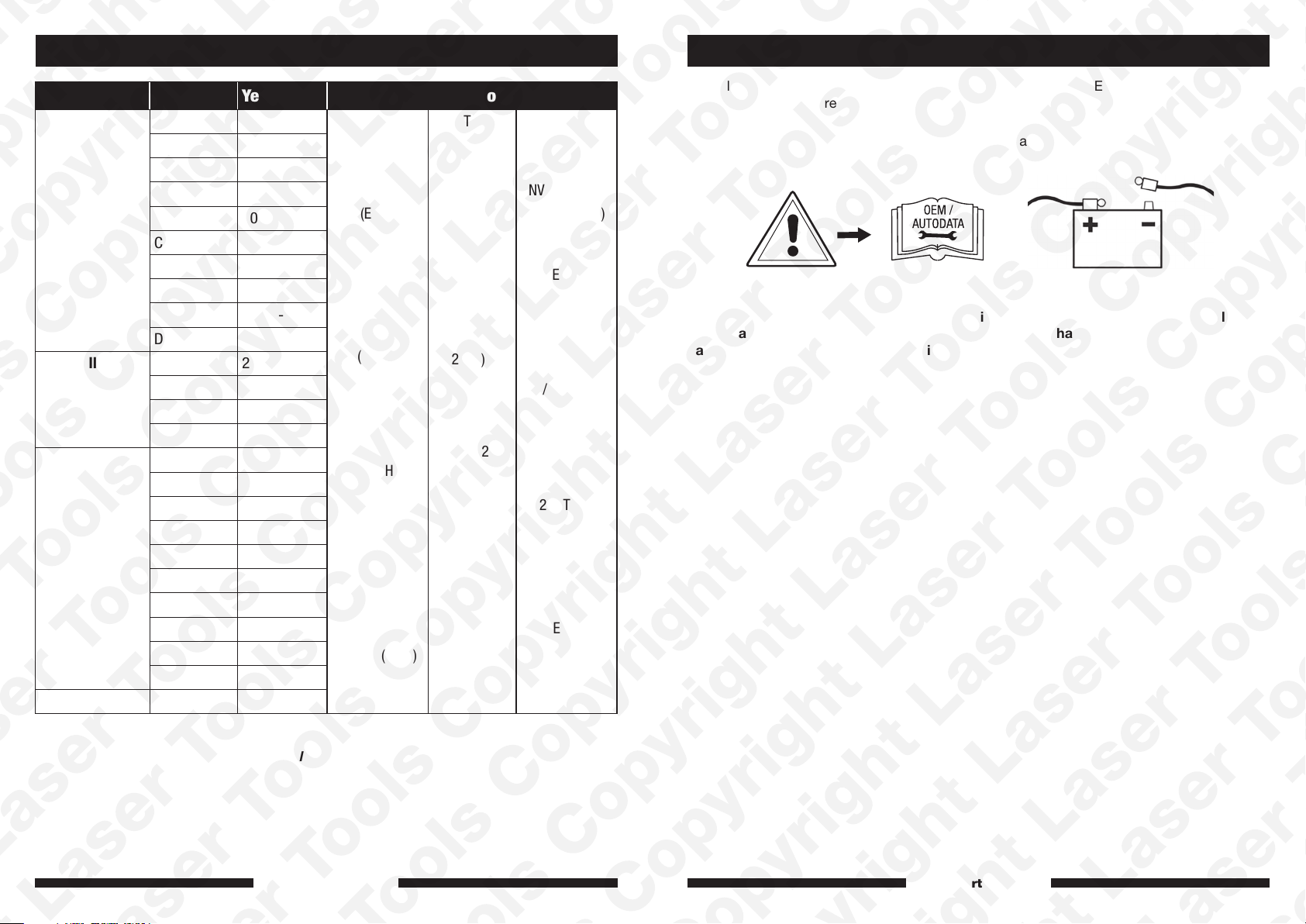
The following instructions are for guidance only. Please refer to OEM derived data such as
the vehicle manufacturers’ own data or Autodata.
The use of this engine timing tool kit is purely down to the user’s discretion and The Tool
Connection Ltd. cannot be held responsible for any damage caused whatsoever.
Warning – Incorrect or out of phase engine timing can result in damage to the valves.
It is always recommended to turn the engine slowly, by hand, and to re-check the
camshaft and crankshaft timing positions.
Always refer to the website for the most up to date applications:
www.lasertools.co.uk/product/8514
www.lasertools.co.uk www.lasertools.co.uk
54
Page 4
InstructionsInstructions
Component Descriptions:
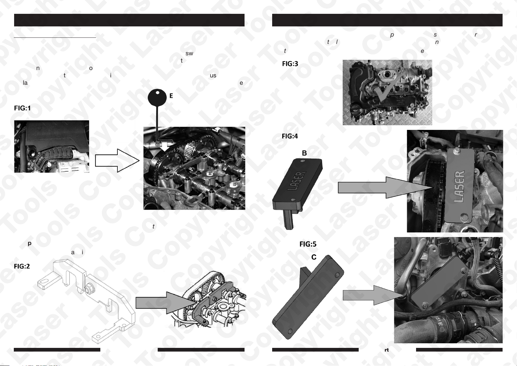
Component E = Cambelt checking tool:
It is possible to check the cambelt condition by checking it for swell. This can be
done easily without dismantling the engine. Using component E through the oil filler
cap opening, it is possible to confirm if the belt has swollen or not. If the checking
gauge (E) does not fit on the belt it indicates the belt has swollen and must be
replaced (figure 1). It is also advisable to remove the engine sump and clean out the
oil pickup.
NOTE: When working on an engine with a split cam cover as shown in figure 3, use
camshaft alignment tools (B) and (C) as shown in figures 4 and 5.
To fit component C the brake vacuum pump must be removed.
NOTE: When working on earlier engines that do not have a split plastic cam cover
use camshaft setting tool (D) to clamp the camshafts in place as shown in figure 2:
Component D = Camshaft Alignment Assembly
Assemble the camshaft timing tool (D) and fit on the camshafts as shown in figure 2.
www.lasertools.co.uk www.lasertools.co.uk
76
Page 5
InstructionsInstructions
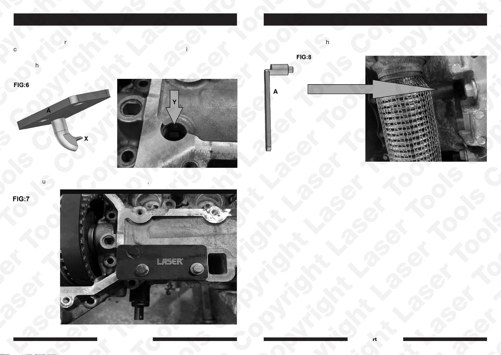
Component F = Exhaust Camshaft Alignment
For additional accuracy and to help remove unwanted play from the exhaust
camshaft insert (F) from the top of the cam cover box and locate it on the corner of
the square on the exhaust camshaft as shown in figure 6.
Ensure that the finger (X) engages properly with the corner on the square on the
camshaft (Y).
Bolt down using 2 cover bolts as shown in figure 7.
Component A = Flywheel Alignment Tool
Insert into flywheel as shown in figure 8.
www.lasertools.co.uk www.lasertools.co.uk
98
Page 6
Instructions
Safety Warnings - please read
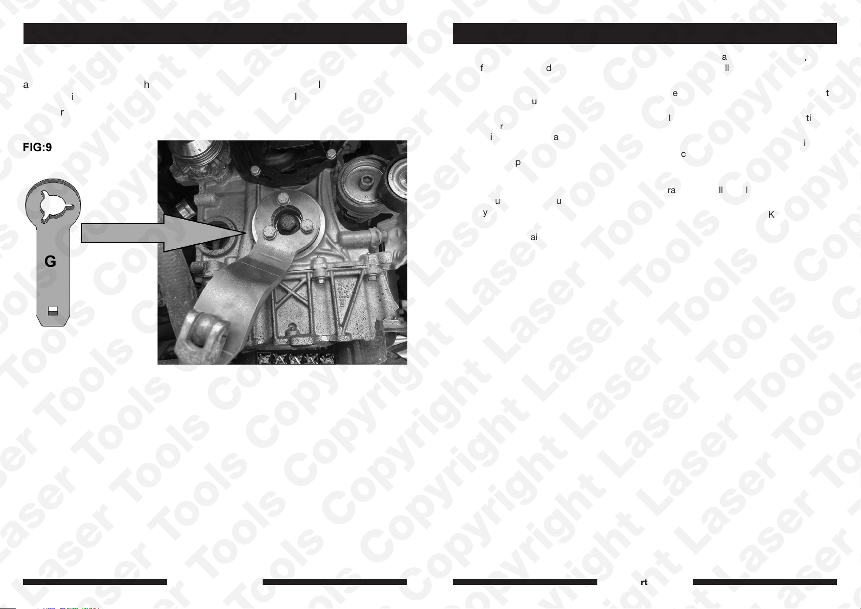
Component G = Crankshaft Holding Tool
G is specially designed to bolt to the crankshaft in place of the front pulley and
allow the crankshaft to be held with a 1/2" drive breaker bar to allow the user to
loosen or tighten the main crankshaft sprocket without overloading the timing tools.
See figure 9.
• If the engine has been identified as an
Interference engine, damage to the engine
will occur if the timing belt has been
damaged. A compression check of all
the cylinders should be taken before the
cylinder head (s) are removed.
• Do not turn crankshaft or camshaft when
the timing belt/chain has been removed.
• To make turning the engine easier,
remove the spark plugs/glow plugs or
injectors.
• Observe all tightening torques.
• Do not turn the engine using the camshaft
or any other sprocket.
• Disconnect the battery earth lead (check
Radio code is available).
• Do not use cleaning fluids on belts,
sprockets or rollers.
• Some toothed timing belts are not
interchangeable. Check the replacement
belt has the correct tooth profile.
• Always mark the belt with the direction of
running before removal.
• Do not lever or force the belt onto its
sprockets.
• Do not use timing pins to lock the
engine when slackening or tightening the
crankshaft pulley bolts.
• ALWAYS REFER TO A REPUTABLE
MANUFACTURERS WORKSHOP
MANUAL.
www.lasertools.co.uk www.lasertools.co.uk
1110
Page 7

Our products are designed to be used correctly and with care for the purpose for which they
are intended. No liability is accepted by the Tool Connection for incorrect use of any of our
products, and the Tool Connection cannot be held responsible for any damage to personnel,
property or equipment when using the tools. Incorrect use will also invalidate the warranty.
If applicable, the applications database and any instructional information provided has been
designed to offer general guidance for a particular tool’s use and while all attention is given
to the accuracy of the data no project should be attempted without referring first to the
manufacturer’s technical documentation (workshop or instruction manual) or the use of a
recognised authority such as Autodata.
It is our policy to continually improve our products and thus we reserve the right to alter
specifications and components without prior notice. It is the responsibility of the user to
ensure the suitability of the tools and information prior to their use.
www.lasertools.co.uk
8514_Instructions_V2
 Loading...