

Page 1
Engine Timing Tool Kit
Audi 2.5L TFSi
Part No. 8367
Instructions
www.lasertools.co.uk
Page 2
Developed to allow the user to lock Audi 2.5L TFSi petrol engines in their “timed”
position so that the camshaft drive chain can be safely removed and replaced or
the engine timing checked. Includes the specially shaped camshaft adjuster holding
tool specifically designed for the 2.5L engine with engine codes DAZA, DNWA.
• Applications include: Audi TT (2016 - 2018), Q3 & Q3 RS (2019-), RS3 Saloon
(2016 - 2018) & RS3 Sportback (2016 - 2018).
• Specifically designed for engine codes DAZA & DNWA - 2.5L TFSi.
• Equivalent to OEM T03003, T40264/2A, T40069, T40011, T03006, T40297.
• Use in accordance with OEM instructions.
For earlier 2.5L TFSi engines, see Laser Part No. 6715.
ComponentsIntroduction
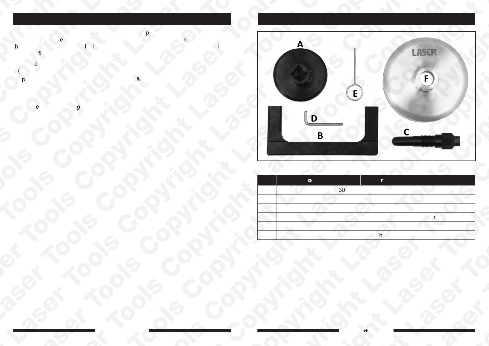
Ref. Comp. Code OEM Ref. Description
A C753 T03003 Crankshaft Pulley Bolt Adaptor
B C914 T40264/2A Cam Locking Tool
C C357 T40069 Crankshaft Locking Pin
D C284 T40011 Secondary Chain Tensioner Pin
E C282 T03006 Primary Chain Tensioner Pin
F C999 T40297 Camshaft Adjuster Holding Tool
www.lasertools.co.uk
www.lasertools.co.uk
32
Page 3
Applications
Instructions
Manufacturer Model Type Year Engine Codes
Audi
RS3 (8VM/8VF) 2016 - 2021 2.5L TFSi
RS Q3 (F3B/F3N) 2019 - on DAZA
TT (FV3/FV9) 2016 - 2018 DNWA
TT (FVP/FVR) 2019 - on
Always refer to the website for most up to date applications:
www.lasertools.co.uk/product/8367
Instructions
The following instructions are for guidance only. Please refer to OEM derived data such as
the vehicle manufacturers’ own data or Autodata.
The use of this engine timing tool kit is purely down to the user’s discretion and The Tool
Connection Ltd. cannot be held responsible for any damage caused whatsoever.
NOTE:
• Access to the timing chains requires engine and transmission removal.
• Ensure the engine timing marks are aligned as per OEM instructions.
• Set timing at TDC cylinder 1 ensuring the threaded holes through the
camshafts face up.
Component A
Component A is used to turn the crankshaft when the front pulley has been
removed.
Note: Turn engine in normal direction of rotation (unless otherwise stated).
www.lasertools.co.uk www.lasertools.co.uk
54
Page 4
InstructionsInstructions
Component B
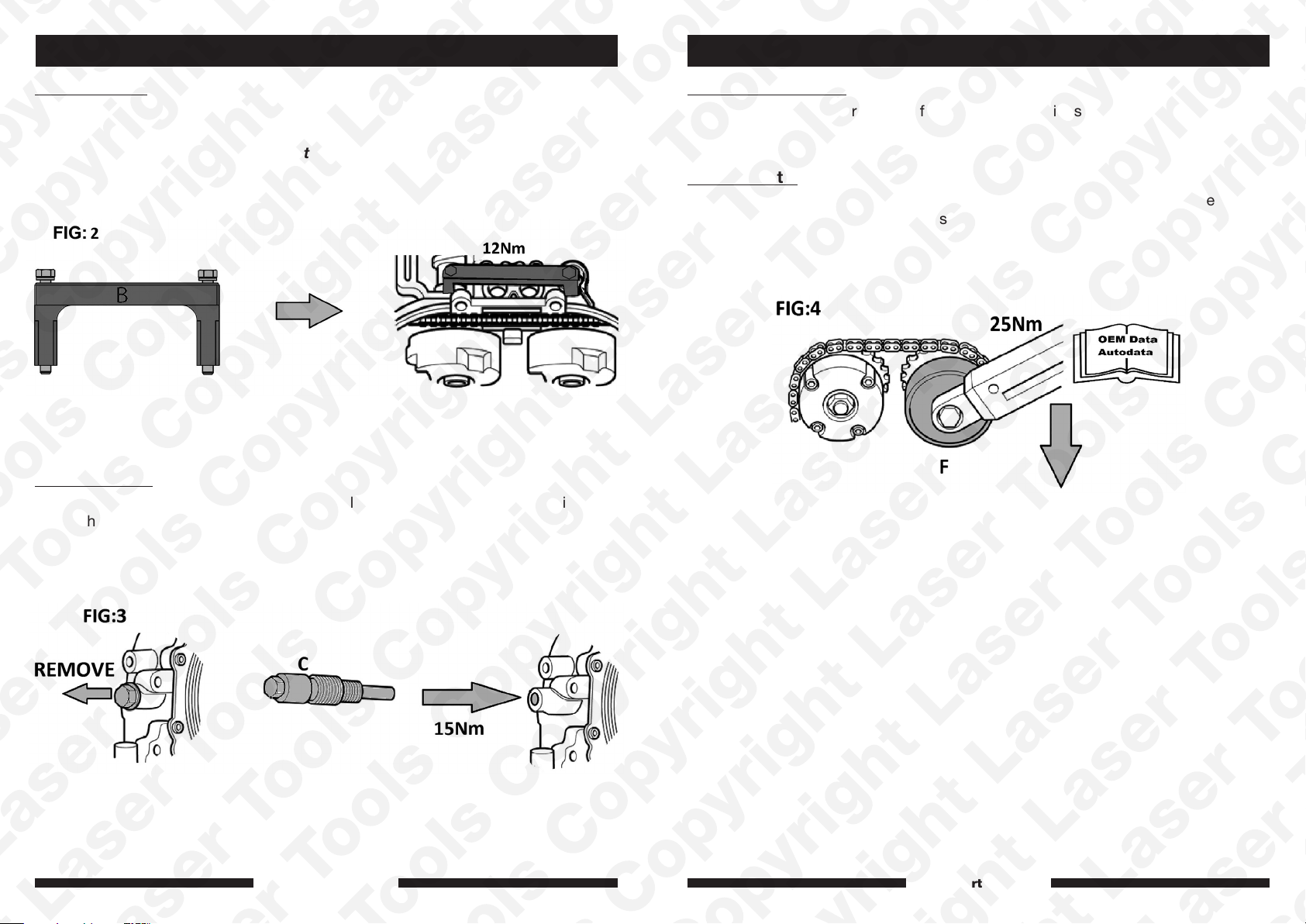
With the camshaft and crankshaft aligned, fit the camshaft locking tool (B) as shown
in figures 1 & 2.
Note: threaded holes in the camshafts must point up.
Component C:
Remove the blanking plug from the cylinder block and fit the crankshaft locking pin
(C) as shown in figure 3.
Components D & E:
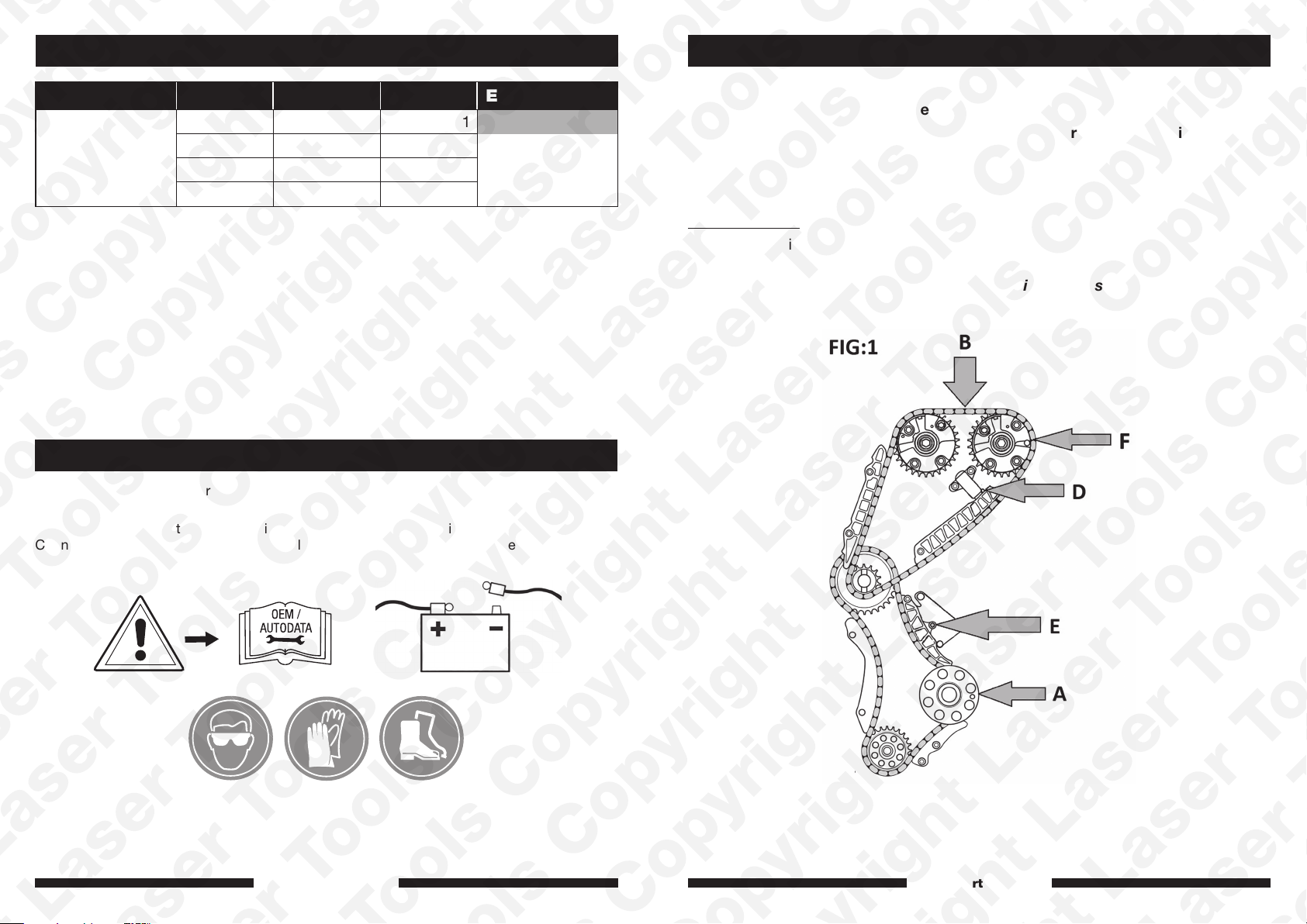
Set both chain tensioners in their fully retracted positions using the chain tensioner
locking pins (D & E) as shown in figure 1 above.
Component F
Use the camshaft adjuster holding tool (F) to hold the camshafts when loosening
and tightening the sprocket fixings as well as for setting the VVT sprockets. Use in
accordance with engine specific OEM data, see figure 4.
www.lasertools.co.uk www.lasertools.co.uk
76
Page 5

Safety Warnings - please read
• If the engine has been identified as an
Interference engine, damage to the engine
will occur if the timing belt has been
damaged. A compression check of all
the cylinders should be taken before the
cylinder head (s) are removed.
• Do not turn crankshaft or camshaft when
the timing belt/chain has been removed.
• To make turning the engine easier,
remove the spark plugs/glow plugs or
injectors.
• Observe all tightening torques.
• Do not turn the engine using the camshaft
or any other sprocket.
• Disconnect the battery earth lead (check
Radio code is available).
Our products are designed to be used correctly and with care for the purpose for which they
are intended. No liability is accepted by the Tool Connection for incorrect use of any of our
products, and the Tool Connection cannot be held responsible for any damage to personnel,
property or equipment when using the tools. Incorrect use will also invalidate the warranty.
If applicable, the applications database and any instructional information provided has been
designed to offer general guidance for a particular tool’s use and while all attention is given
to the accuracy of the data no project should be attempted without referring first to the
manufacturer’s technical documentation (workshop or instruction manual) or the use of a
recognised authority such as Autodata.
It is our policy to continually improve our products and thus we reserve the right to alter
specifications and components without prior notice. It is the responsibility of the user to
ensure the suitability of the tools and information prior to their use.
• Do not use cleaning fluids on belts,
sprockets or rollers.
• Some toothed timing belts are not
interchangeable. Check the replacement
belt has the correct tooth profile.
• Always mark the belt with the direction of
running before removal.
• Do not lever or force the belt onto its
sprockets.
• Do not use timing pins to lock the
engine when slackening or tightening the
crankshaft pulley bolts.
• ALWAYS REFER TO A REPUTABLE
MANUFACTURERS WORKSHOP
MANUAL.
www.lasertools.co.uk
8367_Instructions_V3
 Loading...