

Page 1
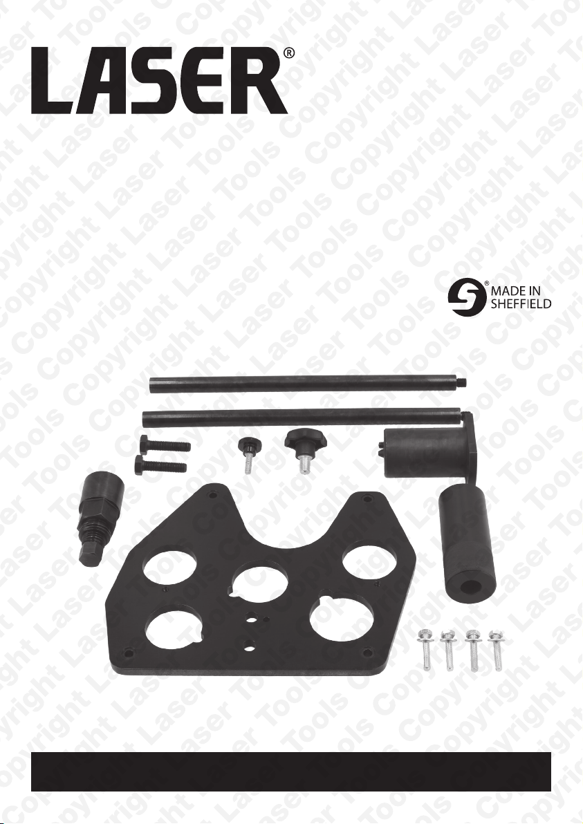
Balance Shaft Removal
& Installation Kit
JLR 2.0L Diesel
Instructions
Part No. 8271
www.lasertools.co.uk
Page 2
Designed to allow the safe removal, fitting and timing of the gear driven balance
shafts found on the Jaguar Land Rover AJ200 2.0L diesel engines.
NOTE: For camshaft timing Laser recommend the use of 7430 kit - sold separately.
• For removal, refitting and setting of the AJ200 diesel balance shafts.
• Applications include: Jaguar E-Pace (from 2017), F-Pace (from 2016), XE (from
2015), XF (from 2015). Land Rover Discovery (from 2017), Discovery Sport (from
2015), Range Rover Evoque (2015 - 2019), Range Rover Sport (2016 - 2018),
Range Rover Velar (from 2017).
• Engine codes include: 2.0L diesel AJ200D, AJ200/204DTA, AJ200/204DTD, AJ200D/204DT, AJ-200D/204DTA, .
• Equivalent to OEM refs. JLR-303-1662, JLR-303-1663-1, JLR-303-1663-2, JLR303-1663-3, JLR-303-1664, JLR-303-1665.
• Use in accordance with OEM instructions.
ComponentsIntroduction
www.lasertools.co.uk
Ref.
Comp.
Code
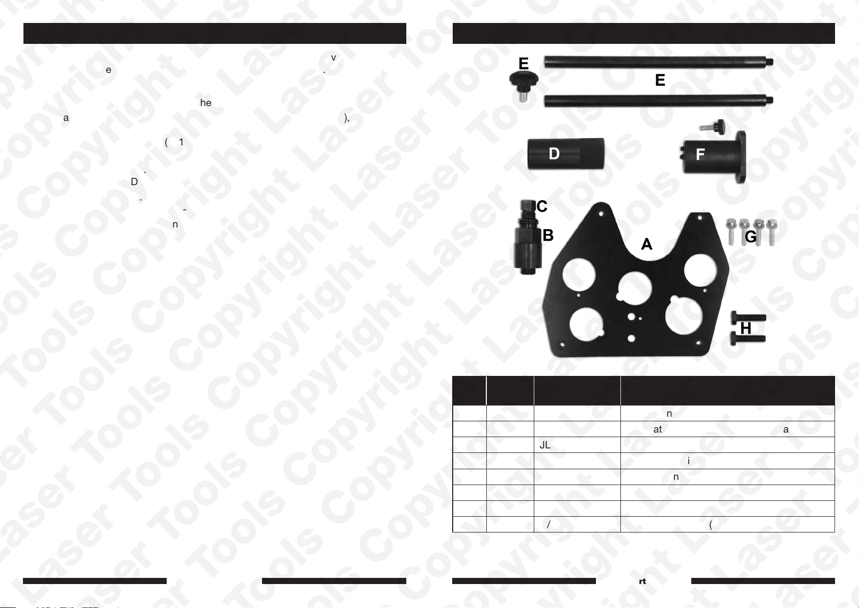
A C983 JLR-303-1662 TDC Alignment Plate
B C984 JLR-303-1663-2 Separator Body (Balance Shaft Gear)
C C985 JLR-303-1663-1 Separator Force Screw (Balance Shaft Gear)
D C986 JLR-303-1663-3 Separator Guide (Balance Shaft Gear)
E C987 JLR-303-1665 Remover/Installer Guide Rod
F C988 JLR-303-1664 Aligner – (Balance Shaft and Screw)
G N/A N/A M6 Bolts for “A” (x4)
H N/A N/A M10 Bolts for “A” (x2)
OEM Ref. Description
www.lasertools.co.uk
32
Page 3
InstructionsApplications
Manufacturer Model Type Year Engine Codes
Land Rover
Jaguar
Defender (L663)
Discovery
Sport
Discovery (L462) Sd4, Td4 2017 - on
Range Rover
Evoque
Range Rover
Evoque
Range Rover
Sport
Range Rover
Velar
E-Pace (X540) D150, D180, D240 2017 - on
F-Pace (X761)
XE (X760)
XF (X260)
Always refer to the website for most up to date applications:
(L550)
(L538) eD4, SD4, TD4 2015 - 19
(L551)
(L494) SD4 2016 - 18
(L560)
www.lasertools.co.uk/product/8271
SD4 D200, SD4
D240
eD4, SD4, TD4,
D150, D165, D180,
D200, D240 MHEV
D150, D165, D180,
D200, D240 MHEV
D180, D240, D200
MHEV
20d, 25d,
E-Performance,
D165, D200 MHEV
20d, 25d,
E-Performance,
D240 MHEV
20d, 25d, D200
MHEV
2019 - on
2015 - on
2019 - on
2017 - on
2016 - on
2015 - on
2015 - on
2.0L
AJ200D
AJ200/204DTA
AJ200/204DTD
2.0L
AJ-200D/204DT
AJ-200D/204DTA
Instructions
Balance shaft removal:
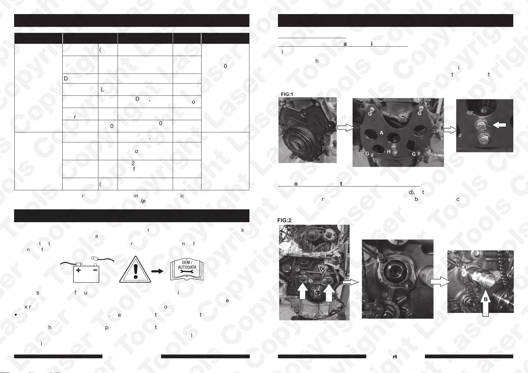
Component A – Crankshaft TDC Alignment Plate
Align the engine timing marks as per OEM instructions.
Working from the front of the engine with crankshaft pulley and front engine cover removed
(see figure 1), fit the crankshaft TDC alignment plate (A). Ensure the pin in the crankshaft
is aligned with hole in the plate so that the 2 crankshaft mounting bolts (H) can be fitted as
shown. Fit bolts (H) to lock the plate and crankshaft in place.
Component B – Separator Body (Balance Shaft Gear)
Working from the rear of the engine (timing chain end), with the flywheel and timing chain
covers removed, remove the balance shaft gear fixing bolts and screw component “B” into
the gear as shown in figure 2.
The following instructions are for guidance only. Please refer to OEM derived data such as the vehicles
manufacturers’ own data or Autodata.
The use of this tool is purely down to the user’s discretion and The Tool Connection Ltd. cannot be held
responsible for any damage caused what so ever.
• Always refer to manufacturer engine specific data and instructions.
• The balance shafts are held in position at the back (timing chain end) of the engine. For
extraction the shafts are pushed forward out of the front of the engine.
• The balance shafts are gear driven. The gears must stay in place while the shafts are
pushed out. For this reason Laser recommend you remove and refit one shaft at a time to
allow the shaft gear to be held in place by component B.
• Removal of the balance shafts requires engine removal and removal of the transmission.
• For engine camshaft timing, please see Laser Part No. 7430.
www.lasertools.co.uk www.lasertools.co.uk
54
Page 4
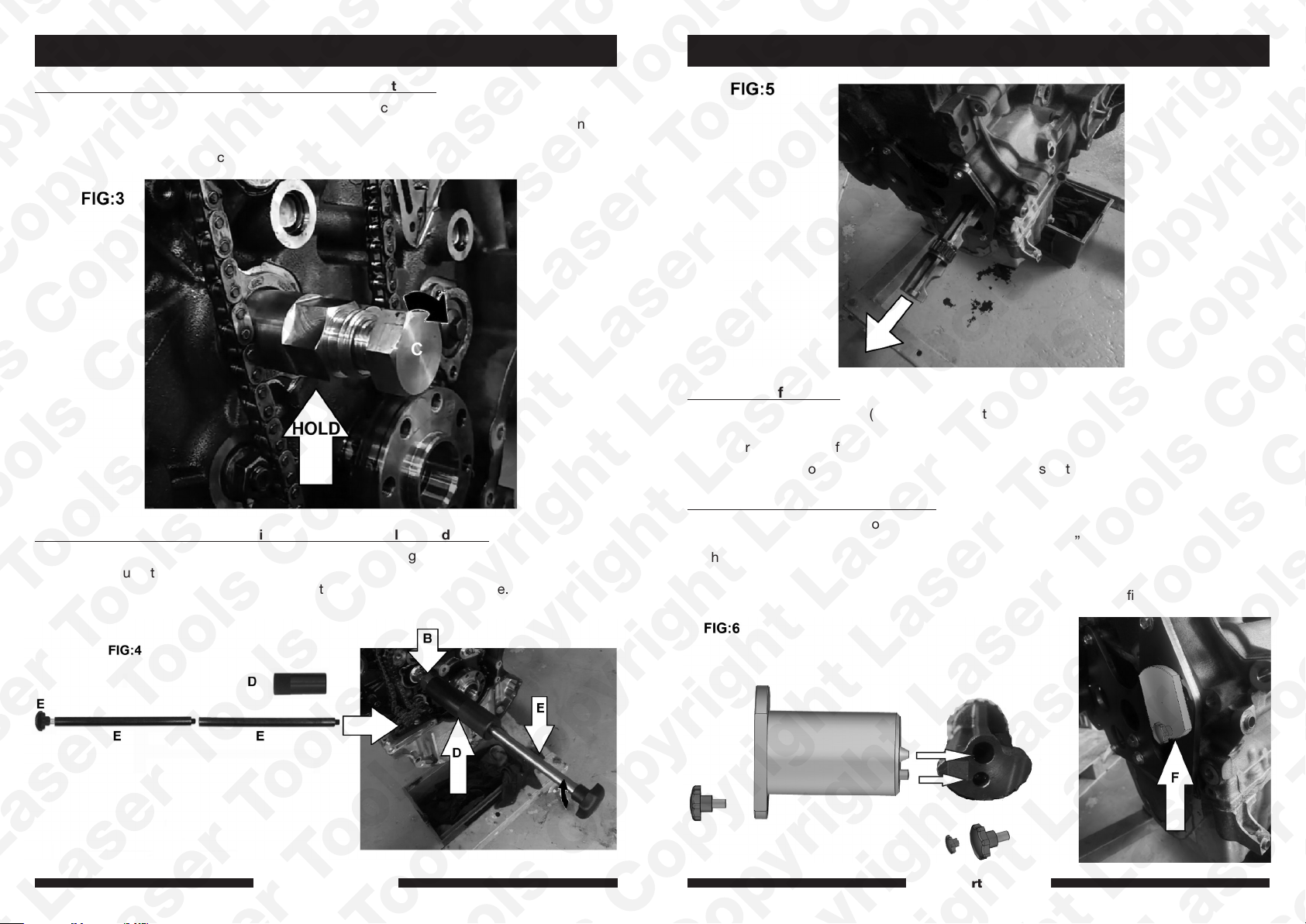
Component C – Separator Force Screw (Balance Shaft Gear)
Holding component “B” with a suitable spanner, screw component “C” to 30Nm then tap
with a copper mallet to release the taper in the gear. Continue turning “C” until the balance
shaft has been pushed out of the gear as shown in figure 3. Remove the force screw (C)
leaving component “B” in place.
InstructionsInstructions
Balance shaft fitting:
With the guide rod assembly (E) still in place, attach the replacement balance shaft to the
rod at the front of the engine and pull the balance shaft in to the engine and in to the balance
shaft gear at the back of the engine.
Working from the front of the engine fit component “F” as detailed below.
Components D & E- Separator Guide & Remover/Installer Guide Rod
Screw component “D” on to component “B”. Assemble the guide rod (E) and insert the
assembly through the guide (D) and screw it into the end of the balance shaft. Using the
guide rod assembly (E) push the balance shaft out of the front of the engine. Remove the
shaft. See figures 4 & 5.
www.lasertools.co.uk www.lasertools.co.uk
Component F – Balance Shaft Aligner
With the new balance shaft loosely held in place by the guide rod (E) push the balance shaft
aligner (F) through the TDC alignment plate (A) so the pin in “F” aligns the balance shaft. Fit
the holding screw for “F” as shown in figure 6.
Working from the back of the engine remove components “E, D, C & B”. Fit and tighten the
balance shaft gear holding bolt and torque to the manufacturer’s specification.
76
Page 5

Our products are designed to be used correctly and with care for the purpose for which they
are intended. No liability is accepted by the Tool Connection for incorrect use of any of our
products, and the Tool Connection cannot be held responsible for any damage to personnel,
property or equipment when using the tools. Incorrect use will also invalidate the warranty.
If applicable, the applications database and any instructional information provided has been
designed to offer general guidance for a particular tool’s use and while all attention is given
to the accuracy of the data no project should be attempted without referring first to the
manufacturer’s technical documentation (workshop or instruction manual) or the use of a
recognised authority such as Autodata.
It is our policy to continually improve our products and thus we reserve the right to alter
specifications and components without prior notice. It is the responsibility of the user to
ensure the suitability of the tools and information prior to their use.
www.lasertools.co.uk
8271_Instructions_V3
 Loading...