

Page 1
Part No. 5630
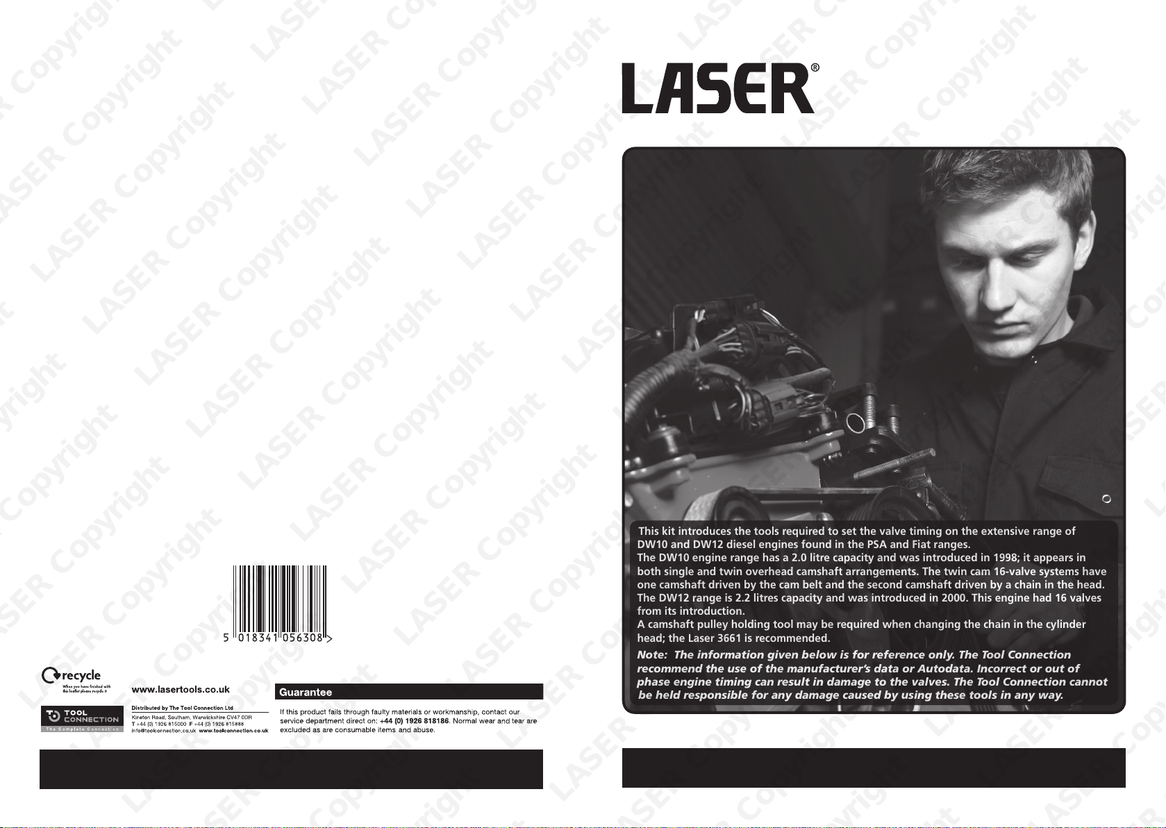
This kit introduces the tools required to set the valve timing on the extensive range of
DW10 and DW12 diesel engines found in the PSA and Fiat ranges.
The DW10 engine range has a 2.0 litre capacity and was introduced in 1998; it appears in
both single and twin overhead camshaft arrangements. The twin cam 16-valve systems have
one camshaft driven by the cam belt and the second camshaft driven by a chain in the head.
The DW12 range is 2.2 litres capacity and was introduced in 2000. This engine had 16 valves
from its introduction.
A camshaft pulley holding tool may be required when changing the chain in the cylinder
head; the Laser 3661 is recommended.
Note: The information given below is for reference only. The Tool Connection
recommend the use of the manufacturer’s data or Autodata. Incorrect or out of
phase engine timing can result in damage to the valves. The Tool Connection cannot
be held responsible for any damage caused by using these tools in any way.
Engine Timing Tool Kit
PSA | Fiat DW10 and DW12
3388
LASER Copyright LASER Copyright LASER Copyright LASER Copyright
LASER Copyright LASER Copyright LASER Copyright LASER Copyright
www.lasertools.co.uk
www.lasertools.co.uk
LASER Copyright LASER Copyright LASER Copyright LASER Copyright
Page 2
Plan Layout
Warning
C
D
J
H G
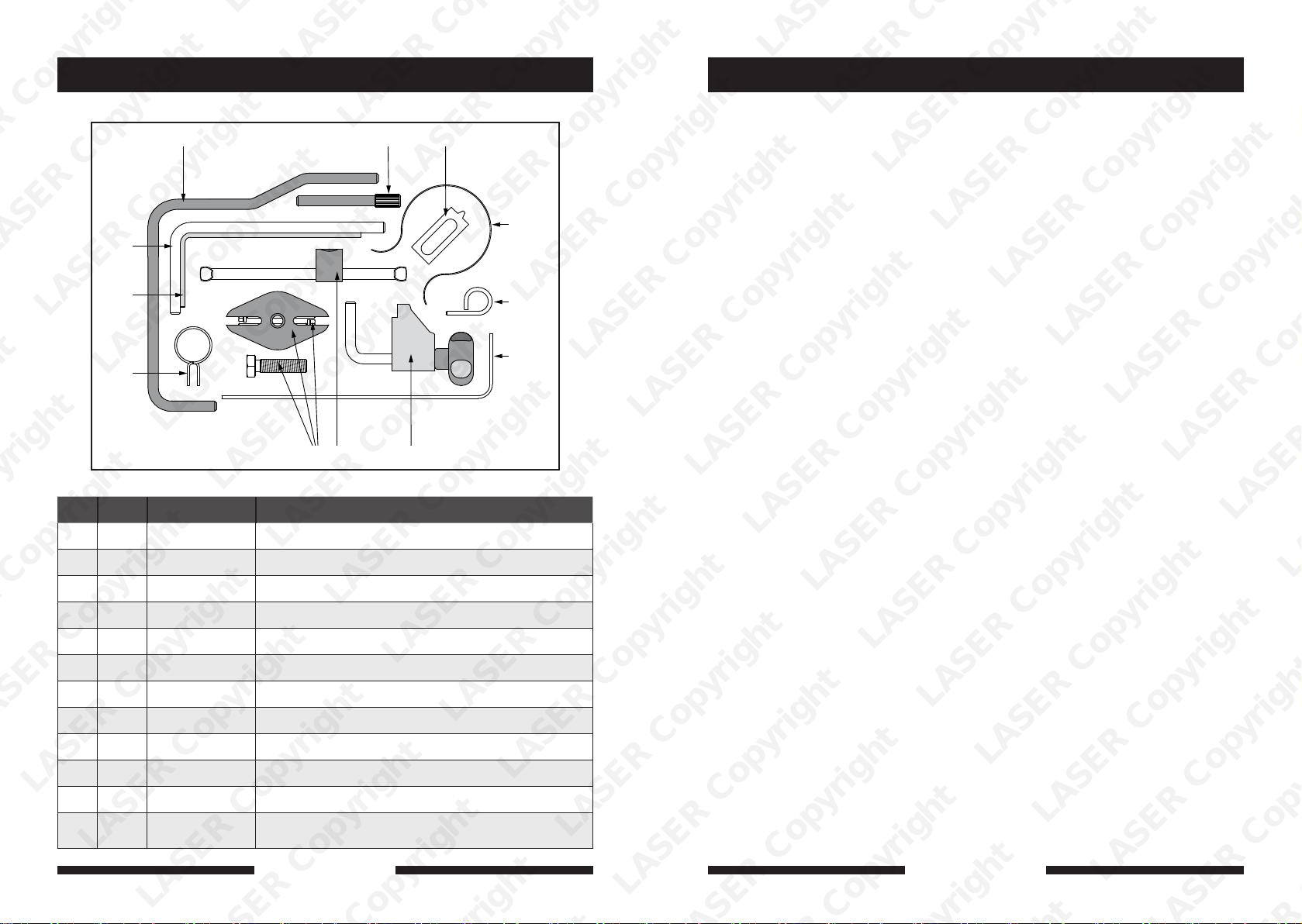
Ref Code OEM Ref Description
A C066 0188Y Crankshaft locking pin (8mm)
B C105 0188M Camshaft locking pin
FBA
Incorrect or out of phase engine timing can result in damage to the valves.
The Tool Connection cannot be held responsible for any damage caused
by using these tools in anyway.
Safety Precautions – Please read
E
I
L
K
• Disconnect the battery earth leads
(check radio code is available)
• Remove spark or glow plugs to make
the engine turn easier
• Do not use cleaning fluids on belts,
sprockets or rollers
• Always make a note of the route of the
auxiliary drive belt before removal
• Turn the engine in the normal direction
(clockwise unless stated otherwise)
• Do not turn the camshaft, crankshaft or
diesel injection pump once the timing
chain has been removed (unless
specifically stated)
• Do not use the timing chain to lock the
engine when slackening or tightening
crankshaft pulley bolts
• Do not turn the crankshaft or camshaft
when the timing belt/chain has been
removed
• Mark the direction of the chain before
removing
• Crankshafts and Camshafts may only be
turned with the chain drive mechanism
fully installed.
• Do not turn crankshaft via camshaft or
other gears
• Check the diesel injection pump timing
after replacing the chain
• Observe all tightening torques
• Always refer to the vehicle
manufacturer’s service manual or a
suitable proprietary instruction book
• Incorrect or out of phase engine timing
can result in damage to the valves
• It is always recommended to turn the
engine slowly, by hand, and to re-check
the camshaft and crankshaft timing
positions
C C351 0188X Flywheel locking pin
D C568 0188Q1 Auxiliary drive belt tensioner locking pin (4mm)
E C121 0188K Cam belt retaining clip
F C115 0188F Flywheel holding tool
G C118 0188J2 Cam belt tensioner tool
H C125 0188P Crankshaft pulley puller / extractor
2 7
I C570 0153AL / 4200TA Cam Belt Tensioner locking pin
J C390 0188AH Crankshaft pulley centralisation tool
LASER Copyright LASER Copyright LASER Copyright LASER Copyright
K C455 0188AD Cam belt clamp
L C569 0188Q2
LASER Copyright LASER Copyright LASER Copyright LASER Copyright
Auxiliary belt tensioner locking and crank pinion
alignment tool (See instructions)
www.lasertools.co.uk
www.lasertools.co.uk
LASER Copyright LASER Copyright LASER Copyright LASER Copyright
Page 3
Instructions
Applications
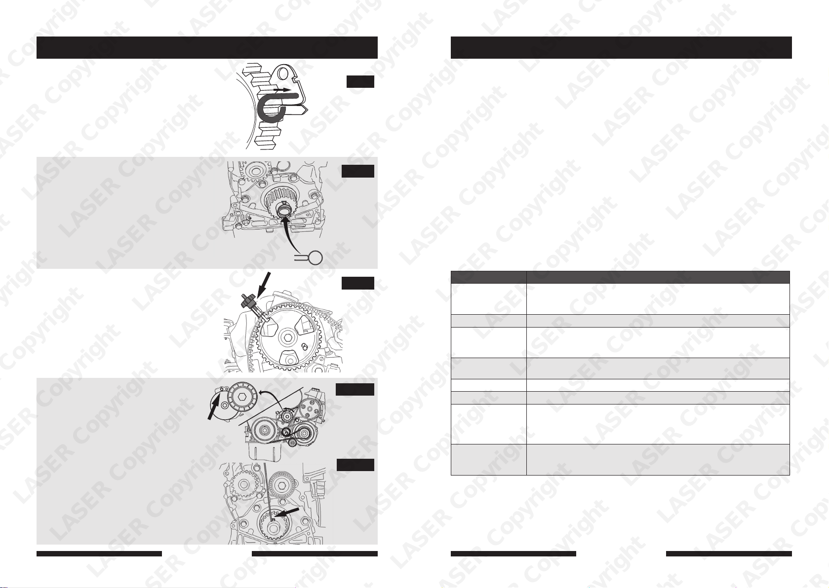
I: Cam Belt Tensioner Locking Pin
Used to lock the spring-loaded tensioners in
their fully retracted position to assist in the
removal and refitting of the belt.
J: Crankshaft Pulley Centralisation Tool
Fit component J as shown (Fig. 10) to ensure
the crankshaft pulley is centralised on the
shaft (aligned with the groove, insert J in
position on both sides of the crankshaft key)
and fit the belt starting at the camshaft pulley
using component K to hold the belt in place
(see Fig. 11). Fit the belt in the following
order: guide roller, crankshaft, water pump,
tensioner (RHR / RHA engines, etc.)
K: Cam Belt Clamp
Used in conjunction with component J to
hold the belt in place while fitting the new
belt to the other pulleys (Fig. 11). Do not
overtighten.
L: Auxiliary belt tensioner locking
and crank pinion alignment tool
Component L has two possible function
depending on the engine code
(refer to manufacturer’s data).
Fig. 12A shows component L used to
lock the spring-loaded cam belt
tensioner in its fully retracted position.
Fig. 12B shows component L used to
centralise the crankshaft pulley for
RHY / RHZ engines; component L is
pushed into the left hand side of the
LASER Copyright LASER Copyright LASER Copyright LASER Copyright
crankshaft pulley groove alongside the
crankshaft keyway.
Fig. 9
Fig. 10
Fig. 11
Fig. 12A
Fig. 12B
The application list for this product has been compiled cross referencing the OEM Tool
Code with the Component Code.
In most cases the tools are specific to this type of engine and are necessary for Cam belt or
chain maintenance.
If the engine has been identified as an interference engine valve to piston damage will
occur if the engine is run with a broken Cam belt.
A compression check of all cylinders should be performed before removing the cylinder
head.
Always consult a suitable work shop manual before attempting to change the Cam belt or
Chain.
The use of these engine timing tools is purely down to the user’s discretion and
Tool Connection cannot be held responsible for any damage caused what so ever.
ALWAYS USE A REPUTABLE WORKSHOP MANUAL
Citroën 2.0lt C4 04-12 | C5 99-12 | C8 02-12 | DS4 11-12
Citroën 2.2lt C-Crosser 07-12 | C5 00 - 09 | C6 07-11 | C8 01-10 Relay | Jumper 02-06
Peugeot 2.0lt: Expert 99-12 | Boxer 01-06 | 206 99-06 | 306 99-02 | 307 01-09
Peugeot 2.2lt:
Fiat 2.0lt: Ulysse 03-11 | Scudo 04-12 | Ducato 01-06
Fiat 2.2lt: Ulysse 02-11 | Ducato 06-12
Engine codes 2.0lt: DW10ATED4 | DW10JATED4 | DW10BTED/L3 | DW10ATD | DW10TD |
Engine codes 2.2lt:
Note: To help with engine identification Citroën and Peugeot usually put the 3 letter engine
codes shown above in the chassis number at the bottom of the windscreen.
Berlingo 99-07 | Dispatch, Jumpy, Relay 99-12 Synergie, Evasion 99-07
Xantia 98-01 | Picasso 99-07, Picasso, Grand Picasso 06-11
406 99-04 | 407 04-11 | 308 07-12 | 607 00-11 | 806 99-02 | 807 05-10
508 11-12 | 3008 09-12 | 5008 09-12 | RCZ 10-12.
406 00-06 | 407 05-11 | 508 11-12 | 607 00-09 | 807 07-10 | 4007 07-10
Boxer 02-06
DW10ATED | DW10BTED | DW10UTD | DW10TD | DW10CTED4
RHA | RHE | RHF | RHG | RHH | RHJ | RHK | RHM | RHR | RHS | RHT | RHV
RHW | RHX | RHY | RHZ
DW12MTED4 | DW12BTED4 | DW12TED4/L4 | DW12UTED |
DW12ATEDL/L4 | DW12CTED4 | 4HK | 4HL | 4HN | 4HP | 4HR | 4HS | 4HT
4HW | 4HX | 4HY | 4HZ
LASER Copyright LASER Copyright LASER Copyright LASER Copyright
6
LASER Copyright LASER Copyright LASER Copyright LASER Copyright
www.lasertools.co.uk
www.lasertools.co.uk
3
Page 4
Instructions
Instructions
Preparation
• Raise the front of the vehicle to allow removal of the front wheels and access to the
inner right hand wheel arch.
• Remove engine top and bottom covers
• Remove right hand inner wheel arch
• Remove auxiliary drive belts and disconnect fuel lines as required. Ensure all fuel lines
are sealed off to ensure no dirt can enter the fuel system.
• Remove right hand engine mount where access demands.
Precaution: We advise removing the exhaust pipe to avoid damaging the flexible section;
this cannot withstand the flexing or bending caused by the engine movement when the
engine mount is removed.
Component Descriptions
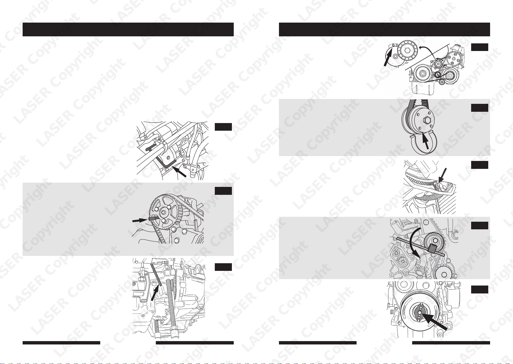
A: Crankshaft Locking Pin
Used to lock the crankshaft in its timed
position by locating in the flywheel
through a hole in the block accessed
from underneath. Never use as a stop to
tighten or loosen the pulley bolt. (Fig. 1)
B: Camshaft Locking Pin
Used to locate the camshaft pulley in
its times position as shown in Fig. 2. Be
aware that on some engines the pin
alignment holes may be in a different
position to the one shown. For example,
the 5 o’clock position for the RHR
(DW10BTED4) engine. If the cam pulley
bolt needs to be removed, use a suitable
pulley holding tool to hold the pulley and
not the locking pin B.
C: Flywheel Locking Pin
Used to lock the crankshaft in its locked
position. Insert into the flywheel via a
timing hole on the front of the engine
block as shown. (Fig. 3) Never use C to
tighten or loosen the pulley bolt against.
Fig. 1
Fig. 2
Fig. 3
LASER Copyright LASER Copyright LASER Copyright LASER Copyright
D: Auxiliary Drive Belt Tensioner
Locking Pin 4mm
Used to lock the auxiliary drive belt
tensioner in its retracted position as
shown in Fig. 4.
E: Cam Belt Retaining Clip
Used to assist in the fitting of the new
belt. When fitting a new belt, always
start at the crankshaft pulley and use the
Retaining clip E to hold the belt in place
while placing the belt on other pulleys.
(Fig. 5)
F: Flywheel Holding Tool
Holds the flywheel and crankshaft
assembly still while loosening or
tightening the front pulley fixing bolt.
Component F engages with the teeth of
the flywheel from underneath the engine.
Do not use any of the other locking tools
for this, as engine can be damaged.
G: Cam Belt tensioner Adjuster Tool
Used to tension the cam belt to the
required tension. Locate component G
in the square drive in the tensioner and
rotate in an anticlockwise direction to
increase the tension on the belt (Fig.7).
Always consult the manufacturer’s
data for the correct tension. Use an
appropriate tension meter.
H: Crankshaft Pulley Puller / Extractor
Aids the removal of the crankshaft pulley.
All threads (locating set screws plus force
screw) must be well lubricated to avoid
thread damage during use and under
tension (see Fig. 8).
Fig. 4
Fig. 5
Fig. 6
Fig. 7
Fig. 8
LASER Copyright LASER Copyright LASER Copyright LASER Copyright
4
LASER Copyright LASER Copyright LASER Copyright LASER Copyright
www.lasertools.co.uk
www.lasertools.co.uk
5
 Loading...