

Page 1
Precautions
• Wear hand and eye protection.
• Be very careful when working with hot, pressurised cooling systems; there is a high
risk of serious scalding.
• If vehicle cooling system is hot, do not attempt to remove the header tank cap or
radiator cap.
• Use proper ventilation and do not breathe in exhaust fumes.
• Dismantle, clean and dry detector components after every use.
• Keep leak detector set clean and in good condition; do not use leak detector if
damaged.
• Always refer to the manufacturer’s service or diagnostic instructions to establish the
correct procedure. These instructions are provided as a guide only.
5524
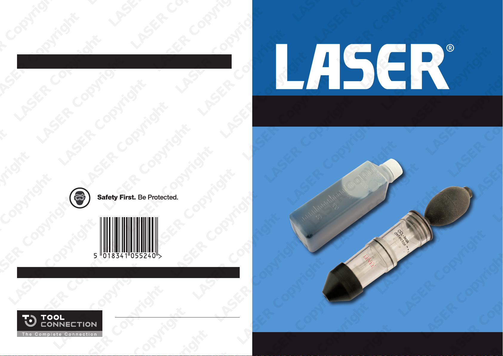
CO2 Combustion Leak Detector
Instructions
Guarantee
If this product fails through faulty materials or workmanship, contact our service
department direct on: +44 (0) 1926 818186. Normal wear and tear are excluded as
are consumable items and abuse.
LASER Copyright LASER Copyright LASER Copyright LASER Copyright
LASER Copyright LASER Copyright LASER Copyright LASER Copyright
LASER Copyright LASER Copyright LASER Copyright LASER Copyright
Distributed by The Tool Connection Ltd
Kineton Road, Southam, Warwickshire CV47 0DR
T +44 (0) 1926 815000 F +44 (0) 1926 815888
[email protected] www.toolconnection.co.uk
www.lasertools.co.uk
Page 2
CO2 Combustion Leak Detector Instructions
This tool is used to diagnose blown head gaskets or cracked cylinder heads by checking
for the presence of CO2 gas in the cooling system. The process of combustion produces
(amongst other gases) 13-14% CO2 in the exhaust and the leakage of this gas into the
cooling system is easily detected.
If combustion gases are present the colour of the indicator test fluid changes from blue to
green/yellow.
The test fluid is reusable (refer to instructions) but is also available separately as
Laser Tools Part No. 5526.
CO -leak
2
detector
CO -leak
2
detector
1. Vehicle should be cold or cool.
If vehicle cooling system is hot, do not
attempt to remove the header tank
cap or radiator cap. Wait until it cools
down.
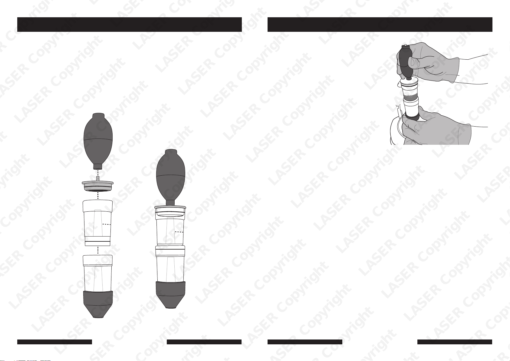
2. Assemble the leak detector; the upper
chamber is a push fit into the lower
chamber, twisting will aid assembly
(refer to diagram).
3. The rubber cone allows the leak
detector to be held in place on a
header tank or radiator opening.
4. Fill the upper chamber of the leak
detector with the supplied test fluid to
the dotted line.
5. Wear thick, protective gloves and eye
protection as there is a risk of escaping
steam and hot water.
6. Remove the header tank cap or
radiator cap (refer to 1. above). Turn on
the engine and let the cooling system
warm up.
7. When cooling system is near normal
operating temperature place the tester
on to the header tank or radiator
opening and hold it down firmly so that
it makes an effective seal against the
opening.
8. As pressure builds into the lower
chamber, you may see bubbles
appearing in the blue test fluid; at this
point pump the rubber bulb to draw
the vapour into the upper chamber and
through the test fluid.
+ H O
2
9. If the fluid turns green/yellow this
indicates the presence of CO2 in the
coolant and the need to investigate
further.
10. Remove the leak detector from the
opening and turn the engine off.
11. Replace the header tank or radiator
cap.
12. Dismantle the upper chamber from the
lower chamber by twisting them apart.
Pump the rubber bulb several times
to draw fresh air through the test fluid.
When it has returned to its original
blue colour it can be returned to the
container and used again.
LASER Copyright LASER Copyright LASER Copyright LASER Copyright
LASER Copyright LASER Copyright LASER Copyright LASER Copyright
www.lasertools.co.uk
www.lasertools.co.uk
LASER Copyright LASER Copyright LASER Copyright LASER Copyright
 Loading...