

Page 1
5209
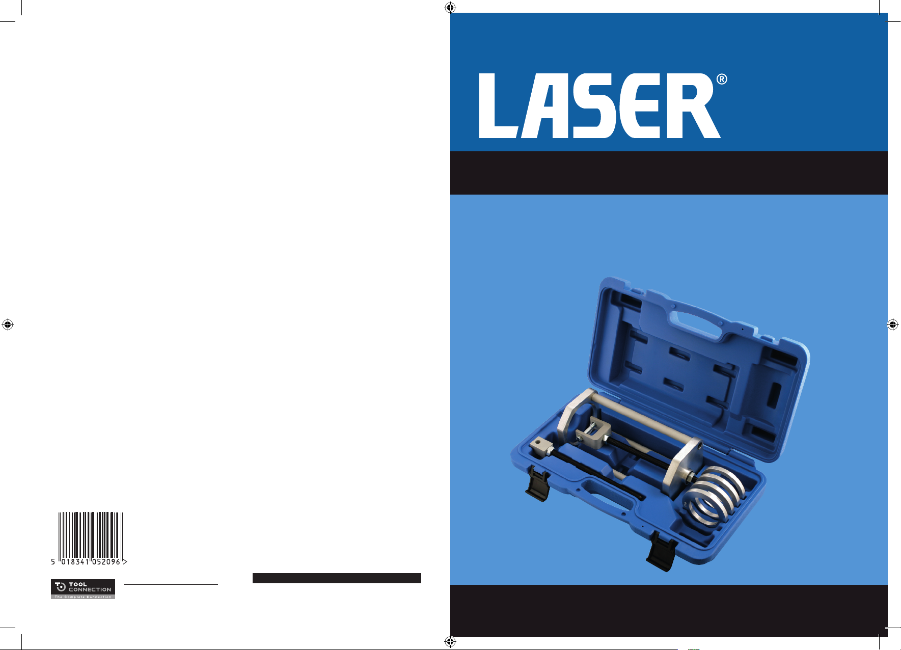
Motorcycle Coil Spring Compressor
60mm | 66mm | 72mm | 75mm Adaptors
Instructions
This tool is designed to remove and install the coil spring on a motorcycle
combined spring | damper unit. Can also be used for suitably-sized
automotive coil-over-damper applications.
Due to the nature of the task and tools, the two threaded rods are regarded as
consumable and not therefore covered by the Tool Connection guarantee.
Replacements available:
Threaded rod, Part No.2610.
Distributed by The Tool Connection Ltd
Kineton Road, Southam, Warwickshire CV47 0DR
T +44 (0) 1926 815000 F +44 (0) 1926 815888
[email protected] www.toolconnection.co.uk
Guarantee
If this product fails through faulty materials or workmanship, contact our service
department direct on: +44 (0) 1926 818186. Normal wear and tear are excluded as
are consumable items and abuse.
www.lasertools.co.uk
Page 2

A B DEC
F
G
I
I
I
I
BCG
A: Compressor frame
B: Threaded rod (2)
C: Securing nuts (2)
D: Force nut
E: Integral thrust bearing
F: Yoke fitting
G: Securing bolt
H: Eye fitting
I: Spring collar adaptors: 60mm | 66mm | 72mm | 75mm
Precautions:
• When compressed, a vehicle or motorcycle road spring is storing a very large
amount of energy. Whilst all possible actions have been taken to reduce the
risk of slippage this risk will always be present.
Instructions:
1. Coil spring compressor unit should be situated on a level, secure surface.
2. Refer to diagram and components diagram.
3. Select the appropriate threaded rod combination with either yoke-type (F) or
eye-type (H) adaptors to fit the end fixing of the damper unit.
Care Point:
Ensure that the threaded rod (B) is screwed fully clockwise into the adaptor
(yoke or eye) and secured tightly with securing nut (C).
4. Lubricate the threaded rod with a lithium-based HMP grease.
5. Insert the threaded rod combination end through the hole in the base plate of
the compressor frame (A). Loosely wind on the force nut (D) a few turns.
6. Choose the appropriate spring collar adaptor (I) that will fit the collar of the
spring | damper unit and insert into rebate in compressor frame end.
7. Place spring/damper unit into compressor frame (A) with spring securing clip |
collar end toward the compressor frame.
8. Attach the yoke or eye of the threaded rod combination to the end fixing of the
damper unit. Make sure securing bolt (G) is tight.
9. Run up the force nut until it is tight against the integral thrust bearing.
10. Using a 19mm spanner or deep socket, tighten the force nut (D) to compress
the coil spring.
11. When the coil spring has been compressed sufficiently, the spring securing clip
| collar will be able to be removed.
12. Then unscrew the force nut to release the pressure on the coil spring. When
pressure has been released damper and coil spring can be removed.
13. Reverse the procedure to reassemble the spring | damper unit or to fit a new
damper unit to the existing coil spring.
• Do not leave compressed spring unattended.
E
A
• Always wear protective head, eye and hand gear. Responsibility for damage
or injury lies with the user.
F
• Threaded rod MUST be adequately lubricated with a lithium-based HMP grease.
• Do not use air tools with this product.
B CD
I
H
2 3
 Loading...