

Page 1
Part No. 5148
Engine Timing Tools
BMW Mini 1.6 | 16v | N14
Peugeot | Citroën EP6DT | DTS
3388
LASER Copyright LASER Copyright LASER Copyright LASER Copyright
LASER Copyright LASER Copyright LASER Copyright LASER Copyright
www.lasertools.co.uk
www.lasertools.co.uk
Page 2
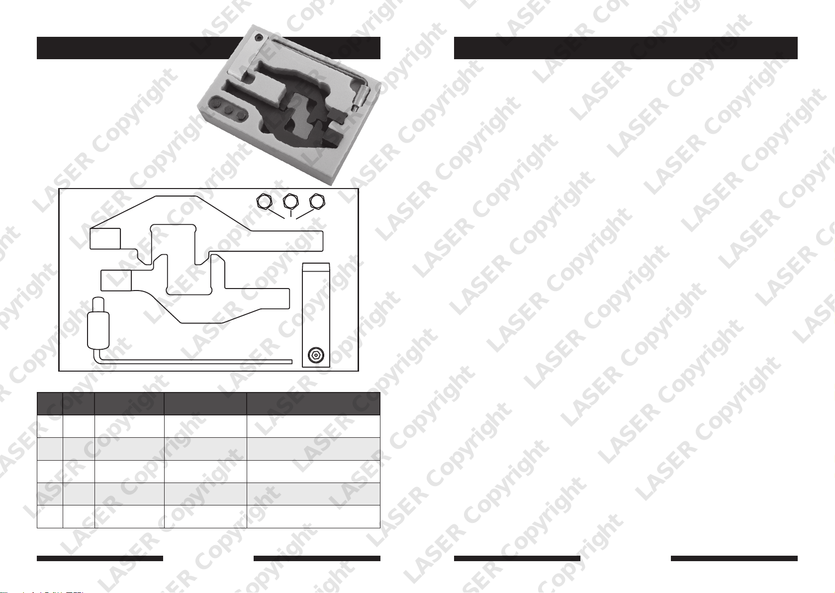
Plan Layout
B
E
A
C
D
Ref Code OEM Ref BMW OEM Ref - PSA Description
A C509 11 9 550 0197-A2 Camshaft Locking Tool - Inlet
B C510 11 9 551 0197-A1 Camshaft Locking Tool - Exhaust
C C511 11 9 552 Camshaft Alignment Clamp
D C512 11 9 590 0197-B Crankshaft Setting Pin
E M6 Setscrews (3)
LASER Copyright LASER Copyright LASER Copyright LASER Copyright
LASER Copyright LASER Copyright LASER Copyright LASER Copyright
2 7
www.eldontools.
www.lasertools.co.ukwww.lasertools.co.uk
Page 3
Warning
Applications
Incorrect or out of phase engine timing can result in damage to the valves.
The Tool Connection cannot be held responsible for any damage caused
by using these tools in anyway.
Safety Precautions – Please read
• If the engine has been identified as
an Interference engine, damage to
the engine will occur if the timing
belt has been damaged. A compresion
check of all the cylinders should be
taken before the cylinder head (s) are
removed.
• Do not turn crankshaft or camshaft
when the timing belt has been
removed
• To make turning the engine easier,
remove the spark plugs
• Observe all tightening torques
• Do not turn the engine using the
camshaft or any other sprocket
• Disconnect the battery earth lead
(Check Radio code is available)
Warning – Incorrect or out of phase engine timing can result in damage
to the valves. It is always recommended to turn the engine slowly, by
hand, and to re-check the camshaft and crankshaft timing positions.
• Do not use cleaning fluids on belts,
sprockets or rollers
• Some toothed timing belts are
not interchangeable. Check the
replacement belt has the correct
tooth profile
• Always mark the belt with the
direction of running before removal
• Do not lever or force the belt onto its
sprockets
• Check the ignition timing after the
belt has been replaced.
• Do not use timing pins to lock the
engine when slackening
or tightening the crankshaft pulley
bolts
• ALWAYS REFER TO A REPUTABLE
MANUFACTURERS WORKSHOP
MANUAL
The application list for this product has been compiled cross referencing the OEM Tool
Code with the Component Code.
In most cases the tools are specific to this type of engine and are necessary for Cam belt or
chain maintenance.
If the engine has been identified as an interference engine valve to piston damage will
occur if the engine is run with a broken Cam belt.
A compression check of all cylinders should be performed before removing the cylinder
head.
Always consult a suitable work shop manual before attempting to change the Cam belt or
Chain.
The use of these engine timing tools is purely down to the user’s discretion and
Tool Connection cannot be held responsible for any damage caused what so ever.
ALWAYS USE A REPUTABLE WORKSHOP MANUAL
Manufacturer Mode Type Engine Code Year
BMW Mini Cooper S 1.6 N14B16A 2007-2010
Peugeot 207 | 307 1.6 EP6DT(5FX) 2006-2010
GT | THP | GTi 1.6 EP6DTS (5FY) 2006-2010
Citroën DS3 | C4 | C4 1.6 EP6DT(5FX) 2006-2010
Grande Picasso TPH 1.6 EP6DT(5FX) 2006-2010
LASER Copyright LASER Copyright LASER Copyright LASER Copyright
LASER Copyright LASER Copyright LASER Copyright LASER Copyright
6
www.lasertools.co.uk
www.lasertools.co.uk
3
Page 4
BMW Mini Cooper S and PSA 1.6 16v Turbo 2007
Instructions – Checking The Timing
BMW Mini and Peugeot have developed a pair of engines. The N14 ranges have been
developed to incorporate the latest technologies to give the best performance, economy
and emissions possible.
This kit has been designed to replace the timing chain on the N14 engines. These engines
are 1.6 Turbo charged petrol engines.
The tools have been specifically designed to allow the camshaft and crankshaft to be locked
in position to correctly check and set the camshaft timing.
NB: It may be necessary to use a pre-load tool on the chain tensioner which is not supplied
in the kit but is available separately – Part No 5153
Preparation
1. The valve timing on these engines
is not set with No1 piston at TDC
but with all the pistons in the
90˚ position. For this reason it is
recommended by the manufacturers
that the spark plugs be removed so
the pistons are checked and are at
the same height in the bores.
2. Where the crankshaft locking pin
slots into the flywheel there are also
balance slots in the flywheel which
the pin could slot into by mistake.
To ensure the tool is in the timing
hole, check the piston heights are
equal with the pin fitted.
3. Remove the cam cover to gain access
to the camshafts
4. Remove the front splash guard
(Mini only)
5. It is highly recommended that the
Vanos unit be checked and if found
faulty replaced (See Manufacturers
Workshop Manual)
Component Descriptions
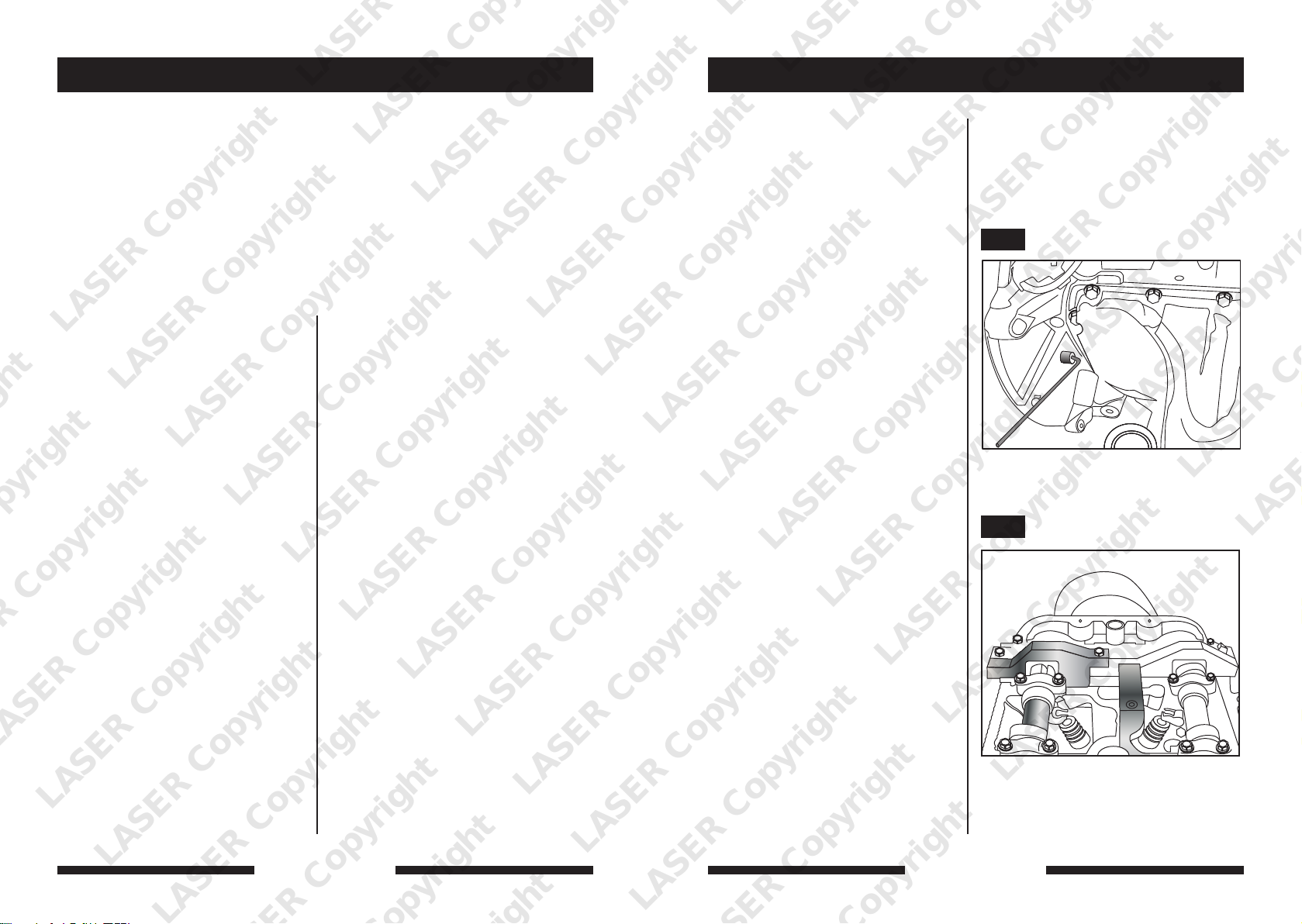
Components A
Inlet camshaft locking tool – this tool fits
on top of the inlet camshaft and locks it
in place. It interlocks with the exhaust
camshaft locking plate (B) and both are
held in place with (C)
Components B/E
Exhaust camshaft locking tool - interlocks
with (A) and is held down by (C).
Components C
Locking Block.
Components D
Crankshaft Locking Pin – used to lock the
crankshaft in position as shown in Fig1.
Component E
Setscrews for (A/B/C) Fig2.
LASER Copyright LASER Copyright LASER Copyright LASER Copyright
Note: these instructions are for reference
only. Please refer to the vehicle
manufacturer’s instructions or other
such reputable data provider. The Tool
Connection recommends the use of
Autodata.
1. Turn the engine in a clockwise
direction using the crankshaft pulley
centre fixing until the Crankshaft
Locking Pin can be slotted in as
shown in Fig. 1
2. Double check correct positioning
by checking the piston heights as
described.
3. Check that the camshafts are in the
correct position by ensuring the
markings ‘IN’ on the inlet camshaft
and ‘EX’ on the Exhaust camshaft
are facing upwards – if not turn the
crankshaft 360˚ and reset.
4. Fit (B) onto the exhaust camshaft as
shown in Fig. 2
5. Fit (A) the inlet camshaft locking
tool as shown in Fig. 2
6. Fit the locking block (C) to hold (A/B).
7. The timing is correct when the
locking tools sit on the surface of the
cylinder head with ease.
Note: In order to adjust the camshaft
timing the cam chain tensioner must
be removed and the camshaft adjuster
centre bolts must be loosened to allow
the crank shaft and 2 cams to be turned
independently of each other so the timing
can be set.
N.B. It may be necessary to use a
pre-load tool on the chain tensioner
which is not supplied in the kit but is
available in (5153).
Please refer to the vehicle manufacturers
data.
Fig. 1
Fig. 2
LASER Copyright LASER Copyright LASER Copyright LASER Copyright
4
www.lasertools.co.uk
www.lasertools.co.uk
5
 Loading...