

Page 1
420 | 428
520 – 530
Chain Sizes
4557
Shortening | Lengthening | Removing | Replacing Chain links
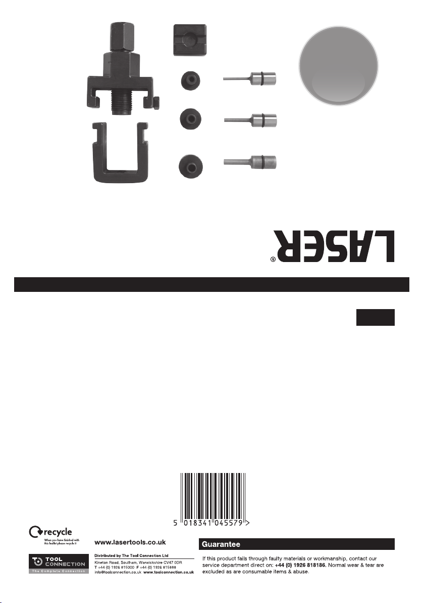
Chain Breaker and Riveting Tool Set
Instructions
Page 2
Chain Breaker and Riveting Tool Set
Shortening | Lengthening | Removing | Replacing Chain links
A comprehensive tool set for shortening and lengthening chains by removing or
replacing the links. Set includes tools for riveting links in place plus plate holder for
connecting links accurately. Use on chain sizes: 520 – 530 | 420 | 428.
Removing link
1 Select link to be removed
2 Place U Holder over the link (B)
3 Select correct size of pin and insert into
pin holder
4 Attach U Holder to pin holder and set on
position X
5 Turn pin holder until the pin contacts the
chain pin (making sure this is centered)
6 Holding pin holder body with 27mm
spanner, use 19mm spanner on head of
pin holder and turn clockwise to push
out pin.
Fit Connecting Link Plate
1 Always grease the connecting pins
before pressing into position.
2 Connect both ends of the chain with a
connecting link including 0 rings if fitted
3 Align pin heads of connecting link with
the pin heads in the inside of the Plate
Holder (C)
4 Fit the correct sized pin into the pin
holder (A)
5 Connect the U Holder with chain to
the Pin Holder (A) and fix at position X
6 Turn pin holder by hand until plate
holder locates the connecting link plate
7 Holding body of pin holder with 27mm
spanner, turn pin holder clockwise with
19mm spanner until the connecting pins
locate the plate holder
8 Disassemble tool and test linkage.
To Rivet a Connecting Link
1 Once the link has been fixed in position
as previous operation
2 Select correct size of riveting pin and
insert it into pin holder (A)
3 Connect Pin Holder (A) to U Holder (B)
and fix at position Y
4 Turn Pin Holder by hand until the pin
locates with connecting pin.
5 Holding body of pin holder with 27mm
spanner turn Pin Holder clockwise with a
19mm spanner until the flared part of the
riveting head contacts with the surface
of the connecting link plate.
Repeat operation for second pin.
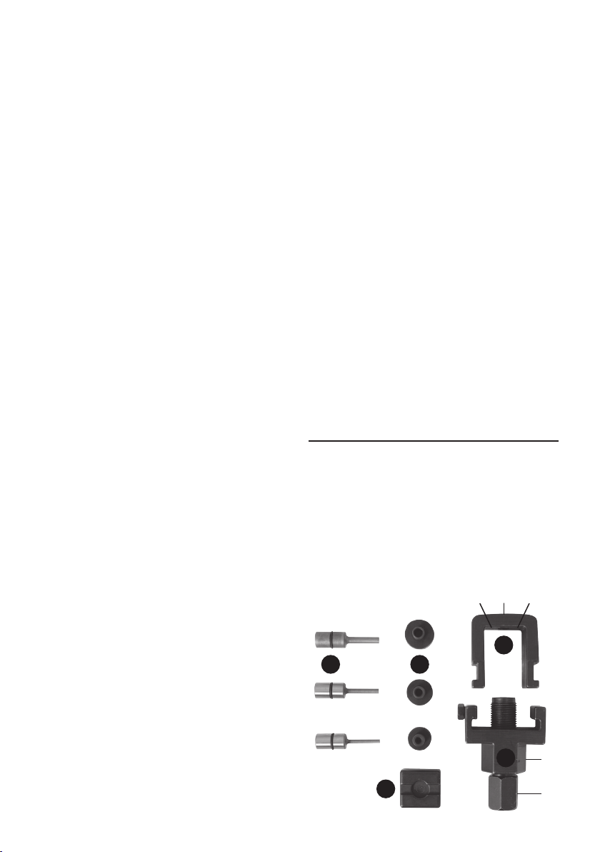
Contents
A Pin Holder with 27mm fixed shaft and
19mm Pin head
B U Holder with X | Y positional fixings
C Plate Holder
D 3 | 4 | 5mm Pins
E 3 | 4 | 5mm Anvils
X U Y
B
ED
A
27mm
C
19mm
 Loading...