

Page 1

Incorrect or out of phase engine timing can result in damage to the valves.
The Tool Connection cannot be held responsible for any damage caused
by using these tools in anyway.
Safety Precautions – Please read
• Disconnect the battery earth leads
(check radio code is available)
• Remove spark or glow plugs to make
the engine turn easier
• Do not use cleaning fluids on belts,
sprockets or rollers
• Always make a note of the route of the
auxiliary drive belt before removal
• Turn the engine in the normal direction
(clockwise unless stated otherwise)
• Do not turn the camshaft, crankshaft or
diesel injection pump once the timing
chain has been removed (unless
specifically stated)
• Do not use the timing chain to lock the
engine when slackening or tightening
crankshaft pulley bolts
• Do not turn the crankshaft or camshaft
when the timing belt/chain has been
removed
• Mark the direction of the chain before
removing
• It is always recommended to turn the
engine slowly, by hand and to re-check
the camshaft and crankshaft timing
positions.
• Crankshafts and Camshafts may only be
turned with the chain drive mechanism
fully installed.
• Do not turn crankshaft via camshaft or
other gears
• Check the diesel injection pump timing
after replacing the chain
• Observe all tightening torques
• Always refer to the vehicle
manufacturer’s service manual or a
suitable proprietary instruction book
• Incorrect or out of phase engine timing
can result in damage to the valves
• It is always recommended to turn the
engine slowly, by hand, and to re-check
the camshaft and crankshaft timing
positions
Part No. 4347
Engine Timing Tools
Ford Zetec
www.lasertools.co.uk
www.lasertools.co.uk
LASER Copyright LASER Copyright LASER Copyright LASER Copyright
Page 2
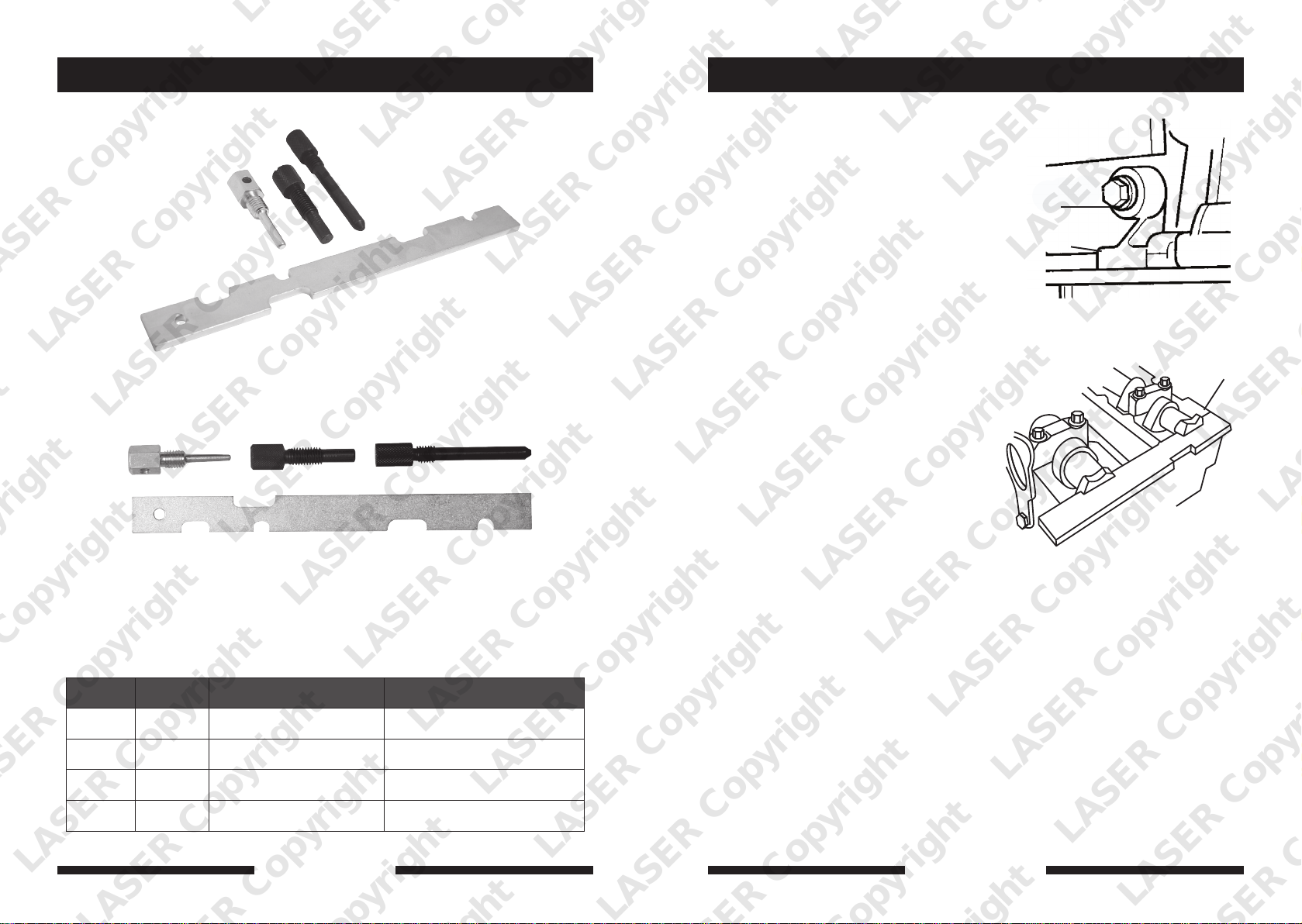
A C B
D
Ref Code Oem Ref. Description
A C035 21-210 | 303-507 Crankshaft Timing Pin
Instruction (DE)
1. Scheiben zur Einstellung/Sicherung der
Nockenwelle werden zur genauen
Anpassung mit einer Bezugskerbe
verwendet, die sich am Ende der
Nockenwelle befindet, wobei die
Oberseite des Nockenwellengehäuses
die Nockenwelle in der Position des
Oberen Totpunktes (OT) hält.
2. Zum Entfernen des
Nockenwellendeckels und des
Zahnriemendeckels den Anweisungen
aus dem Bedienungshandbuch folgen.
3. Motor in der normalen Drehrichtung
drehen, bis die Scheibe zur Einstellung/
Sicherung der Nockenwelle in die
bearbeitete Kerbe am Ende der
Nockenwelle eingefügt werden kann.
4. Der Kurbelwellen OTPositionierungsstift ist so konstruiert,
dass er in den Zylinderblock
geschraubt wird und eine Blockierung
für die Kurbelwelle ermöglicht, die zur
Einstellung der OT-Position
gegenpositioniert wird.
5. Motor in normaler Drehrichtung
drehen, bis die Einstellmarkierung auf
dem Kettenrad der Einspritzpumpe mit
dem Gussansatz auf dem
Steuerungsdeckel auftaucht.
6. Verschlussstopfen vom Zugangsloch
des Zylinderblocks entfernen und
OT-Positionierungsstift aufschrauben.
7. Kurbelwelle langsam im Uhrzeigersinn
drehen, bis die Rippe das Ende des
Stiftes berührt. Zylinder Nummer 1 ist
jetzt beim OT auf Arbeitstakt
eingestellt.
A | B | C
D
B C036 21-163 | 303-574 Crankshaft Timing Pin
C C311 21-259 | 303-748 Crankshaft Timing Tool
D C312 21-162B | 303-376 | 303-376B Alignment Plate
LASER Copyright LASER Copyright LASER Copyright LASER Copyright
2 7
www.eldontools.
www.lasertools.co.ukwww.lasertools.co.uk
Page 3
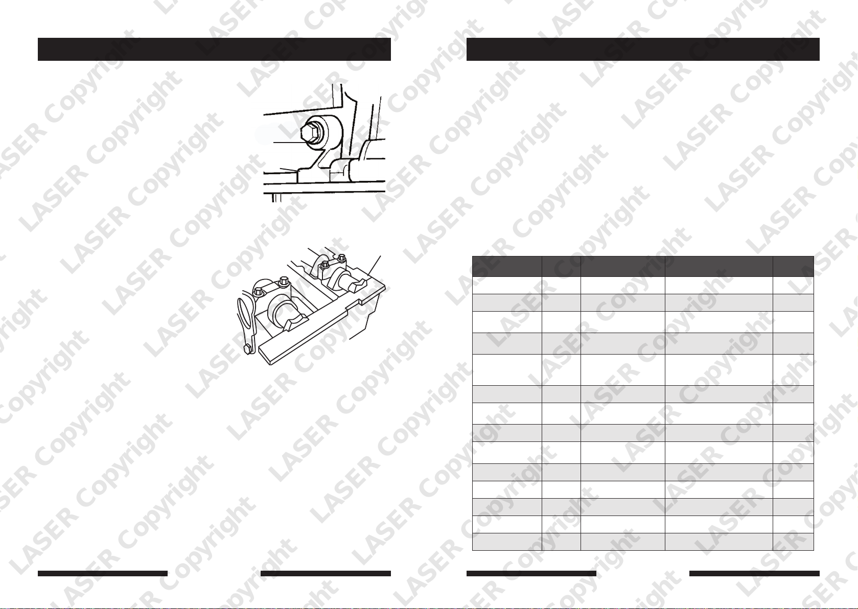
Instruction (ES)
Applications
1. Las placa de consigna/seguridad de eje
de levas se utilizan para alinear bien
una ranura punto de referencia,
situada en un extremo del eje de levas,
con la superficie superior de la caja de
ejes de leva para sujetar el eje de levas
en posición (TDC) de Centro Absoluto.
2. Seguir las instrucciones en el manual
de servicio para remover la cubierta
del eje de levas y la cubierta de la
correa de tiempos (dentada).
3. Girar el motor en dirección normal
hasta que pueda insertarse la placa de
consigna/seguridad en la ranura
mecanizada en el extremo del eje de
levas.
4. El Pin de Localización de (Centro
Absoluto) está diseñado para
enroscarse en el bloque de cilindros y
ofrecer un tope para posicionarlo
contra el cigüeñal para consignar la
posición (Centro Absoluto).
5. Girar el motor en la dirección normal
hasta que la marca de tiempos (poner
a punto) en el piñón de la bomba de
inyección se alinee con al saliente
moldeado en la cubierta de tiempos
(poner a punto).
6. Remover el tapón del agujero de
acceso al bloque de cilindros y enroscar
el pin de localización de TDC (Centro
Absoluto).
7. Girar lentamente el cigüeñal a la
derecha hasta que la banda contacte el
extremo del pin. Ahora el cilindro
número 1 está en el (Centro Absoluto)
de la carrera de ignición.
A | B | C
The application list for this product has been compiled cross referencing the OEM Tool
Code with the Component Code.
In most cases the tools are specific to this type of engine and are necessary for Cam belt or
chain maintenance.
If the engine has been identified as an interference engine valve to piston damage will
occur if the engine is run with a broken Cam belt.
A compression check of all cylinders should be performed before removing the cylinder
head.
Always consult a suitable work shop manual before attempting to change the Cam belt or
Chain.
The use of these engine timing tools is purely down to the user’s discretion and
Tool Connection cannot be held responsible for any damage caused what so ever.
ALWAYS USE A REPUTABLE WORKSHOP MANUAL
D
Manufacturer Model Style Engine Code Year
Ford Cougar 2.0 16v Zetec 1999
Escort Orion 1.6 | 1.8 16v RKC | L1K | L1H 1991-98
Fiesta Puma 1.25 | 1.4
Fiesta XR2i 1.25 | 1.4 | 1.6
Fiesta Fusion 1.25 | 1.4 | 1.6
Focus 1.4 | 1.6 | 1.8 | 2.0 16v 1998-00
Focus 1.8 TDi Zetec
Focus 1.4 | 1.6 Zetec 2002-03
Focus 1.6 | 1.6 16v TI-VCT
Focus CMax 1.6 | 1.8 | 2.0 16v HWDA | HWDB 2003-07
DHA | DHB | DHC
DHD | FHA | FHE
DHA | DHB | DHC | DHE | DHF
DHG | HA | FHE | L1T | L1V
FUJA | FUJB | FXJA | FXJB
FYJA | FYJB | F8JA | F8JB
M7JA | M7JB
FXDA/C | FXDB/D | FYDA/C
FYDB/D | DYDH
1995-97
1997-02
2002-07
2002-03
1998-00
1998-05
Mondeo 1.8 16V L1F | L1J | RKA | RKB | NGA 1993-00
RS1800 1.7 RDB | RQB | RQC 1991-98
Puma 1.25 MHA 1997-2000
Mazda 121 1.7 DHA 1995-98
LASER Copyright LASER Copyright LASER Copyright LASER Copyright
6
www.lasertools.co.uk
www.lasertools.co.uk
3
Page 4
Instruction (GB) Instruction (FR)
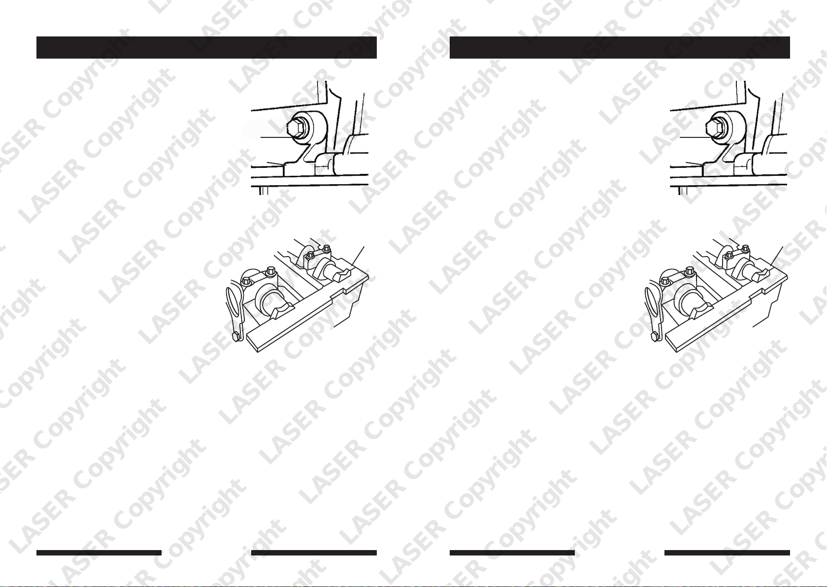
1. Camshaft Setting / Locking Plate is
used to accurately align a datum slot,
located in the end of the camshafts.
The various slots cut into the edge of
the plate permit clearance around
adjacent parts.
2. Follow the service manual instructions
to remove the camshaft cover and
timing belt cover.
3. Turn engine in the normal direction of
rotation until the camshaft setting/
locking plate can be inserted into the
machined slot in the end of the
camshaft.
4. Crankshaft TDC Location Pin is
designed to screw into the cylinder
block and provide a stop for the
crankshaft to be positioned against to
set the TDC position.
5. Turn the engine in the normal
direction of rotation until the timing
mark on the injection pump sprocket
lines up with the cast lug on the timing
cover.
6. Remove the plug from the cylinder
block access hole and screw in the TDC
location pin.
7. Slowly turn the crankshaft clockwise
until the web makes contact with the
end of the pin. Number 1 cylinder is
1. Plaque de réglage /blocage d’arbre à
cames sont utilisées pour aligner avec
précision une encoche repère
positionnée à l’extrémité de l’arbre à
cames, avec la face supérieure du
carter d’arbre à cames afin de tenir
A | B | C A | B | C
D D
l’arbre à cames à la position du point
mort haut (PMH).
2. Suivre les instructions du manuel
d’entretien pour démonter le carter
d’arbre à cames et le carter de la
courroie de distribution.
3. Tourner le moteur dans le sens de
rotation normal jusqu’à ce que la
plaque de réglage /blocage d’arbre à
cames puisse être insérée dans
l’encoche usinée positionnée à
l’extrémité de l’arbre à cames.
4. Broche de centrage de vilebrequin au
PMH est conçue pour se visser dans le
bloc-cylindres et procurer une butée
contre laquelle le vilebrequin se
positionne pour régler la position du
PMH.
5. Tourner le moteur dans le sens de
rotation normal jusqu’au point où le
repère de calage de distribution du
pignon de la pompe d’injection est
aligné avec le repère de centrage
moulé positionné sur le carter de
distribution.
6. Démonter le bouchon du trou d’accès
du bloc-cylindres et visser la broche de
centrage au PMH.
7. Tourner lentement le vilebrequin dans
le sens horaire jusqu’à ce que la toile
touche l’extrémité de la broche. Le
cylindre numéro 1 est alors réglé au
PMH du temps d’allumage.
LASER Copyright LASER Copyright LASER Copyright LASER Copyright
4
www.lasertools.co.uk www.lasertools.co.uk
5
 Loading...