

Page 1

Incorrect or out of phase engine timing can result in damage to the valves.
The Tool Connection cannot be held responsible for any damage caused
by using these tools in anyway.
Safety Precautions – Please read
• Disconnect the battery earth leads
(check radio code is available)
• Remove spark or glow plugs to make
the engine turn easier
• Do not use cleaning fluids on belts,
sprockets or rollers
• Always make a note of the route of the
auxiliary drive belt before removal
• Turn the engine in the normal direction
(clockwise unless stated otherwise)
• Do not turn the camshaft, crankshaft or
diesel injection pump once the timing
chain has been removed (unless
specifically stated)
• Do not use the timing chain to lock the
engine when slackening or tightening
crankshaft pulley bolts
• Do not turn the crankshaft or camshaft
when the timing belt/chain has been
removed
• Mark the direction of the chain before
removing
• It is always recommended to turn the
engine slowly, by hand and to re-check
the camshaft and crankshaft timing
positions.
• Crankshafts and Camshafts may only be
turned with the chain drive mechanism
fully installed.
• Do not turn crankshaft via camshaft or
other gears
• Check the diesel injection pump timing
after replacing the chain
• Observe all tightening torques
• Always refer to the vehicle
manufacturer’s service manual or a
suitable proprietary instruction book
• Incorrect or out of phase engine timing
can result in damage to the valves
• It is always recommended to turn the
engine slowly, by hand, and to re-check
the camshaft and crankshaft timing
positions
Part No. 4076
Engine Timing Tools
Renault dci
LASER Copyright LASER Copyright LASER Copyright LASER Copyright
www.lasertools.co.uk
www.lasertools.co.uk
Page 2
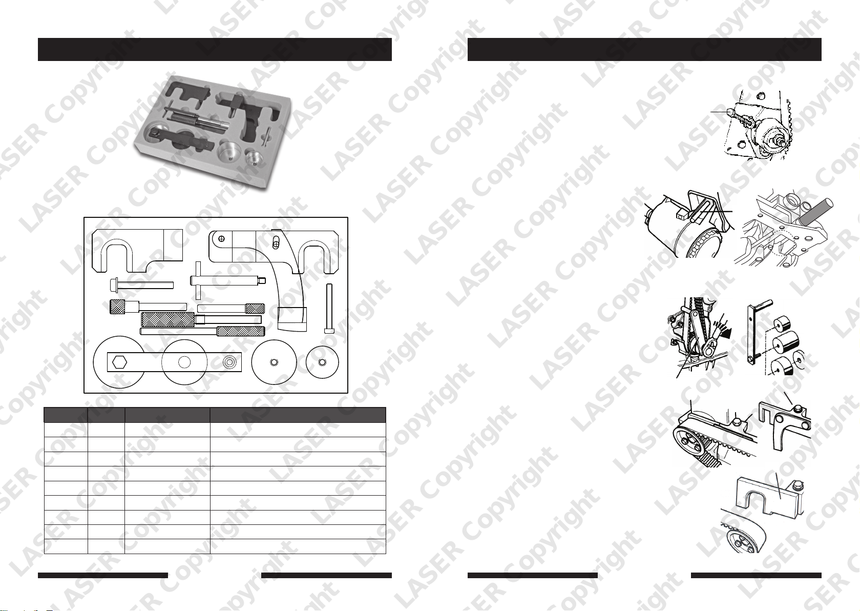
Plan Layout Instruction (DE)
A
Spannwerkzeug
Fur der korrekten Spannung ermöglicht,
zum riemens-Gürtel angewandt zu
werden.
Kurbelwellen-Fixierdorn
Es gibt vier andere Stücke, die in diesem
eingeschlossen werden, das gesetzt wird.
I
H/I
Wie mit der Nockenwelle-Timing-Nadel
werden sie durch den Motorblock
hineingesteckt und gebraucht, die
Kurbelwelle aufzustellen, um die korrekte
riemen des ersten Zylinders zu erreichen.
Es ist wichtig, daß diese Stücke benutzt
werden, um die riemens zu setzen, aber
wird nicht benutzt werden, um das
F
Schwungrad abzuschließen.
G
H
C D
A
G
1
E
2
E
E
Ref Code Oem Code Description
A C037 MOT 1489 Crankshaft Timing Pin
B
C
D
E
F
G
H
I
C067
C099
C101
C281
C182
C179
C180
C181
MOT 1054 Flywheel Locking Pin
MOT 1430 Camshaft Timing Pin
MOT 1543 Tension Pre-Setting Tool
MOT 1538 Hi Pressure Fuel Pump Pulley Locking Pin
MOT 1536 Flywheel Setting Pin
MOT 1537 Camshaft Locking Tool - Exhaust
MOT 1534 Camshaft Locking Tool – Inlet
M6 X 30mm Tensioning Screw
B
Die Auslass-Nockenwelle mit dem Halter F
arretieren und mit der Schraube G sichern.
3
E
Ist das Werkzeug nicht exakt zu montieren,
drehen Sie die Kurbelwelle um 180° in
Drehrichtung. Lösen Sie die Befestigung
der Riemenscheibe, während der
Installation dürfen die Schrauben nicht am
Ende der Langlöcher anliegen.
Der Hebelarm wird am Spanner anliegen.
Die Oberseite des Armes fluchtet mit der
NW-Arretierung, wenn der Spanner gegen
den Urzeigersinn gedreht wird. Verwenden
Sie einen 6 mm Inbus.
D
Montieren Sie die Arretierung H der
Einlass-Nockenwelle an den senkrechten
Abflachungen der Welle.
B
A
E
H
LASER Copyright LASER Copyright LASER Copyright LASER Copyright
2 7
www.eldontools.
www.lasertools.co.ukwww.lasertools.co.uk
Page 3
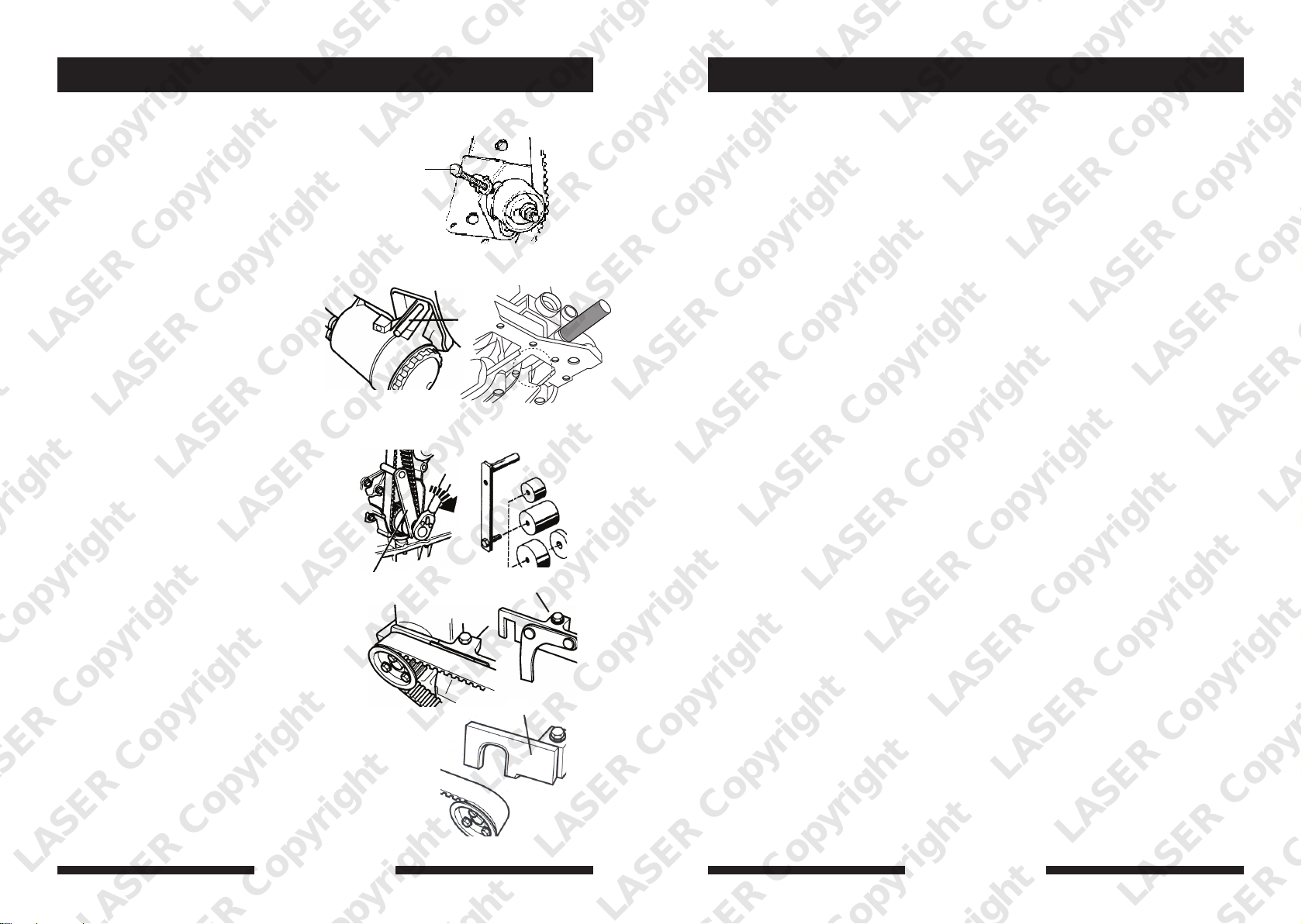
Instruction (ES)
A
Applications
Tornillo de tensado
Que permite aplicar la tensión correcta a la
correa de distribución.
Chavetas de reglaje del cigüeñal
Hay cuatro pedazos diferentes incluidos en
esto puesto. Como con el árbol de levas
que cronometra el alfiler, ellos se insertan
a través del bloque motor y posicionaban
el cigüeñal para lograr la posición de la
oportunidad correcta del primer cilindro.
Es importante que estos pedazos se usan
para poner la posición de la oportunidad,
pero no será usado para cerrar con llave el
volante.
Herramienta de tensado
Para permitir aplicar la pre-tensión
correcta a la correa de distribución. Esta
herramienta tiene 3 el tubo de protección
intercambiables y una espacio para
satisfacer la variedad de tensor usada.
Instale el herramienta de bloques de àrbol
de levas de escape F y contenga lugar que
usa un tornillo de seguridad G.
Si la herramienta no puede encajarse
correctamente, ruede el cigüeñal uno se
vuelve en el sentido de las agujas del reloj.
Modere los broches del diente, pero
verifique eso durante instalación que los
broches no se posicionan al final de las
hendeduras. El brazo de la palanca lega el
contacto de cierre con el tensor. Como un
registro visual la cima del brazo alineará
con el útil fijador del árbol de levas cuando
el tensor se ha vuelto anti-en el sentido de
las agujas del reloj aunque siendo de
tensor que usa un llave 6 mm.
The application list for this product has been compiled cross referencing the OEM Tool
Code with the Component Code.
B
G
A
E
H
D
In most cases the tools are specific to this type of engine and are necessary for Cam belt or
chain maintenance.
If the engine has been identified as an interference engine valve to piston damage will
occur if the engine is run with a broken Cam belt.
A compression check of all cylinders should be performed before removing the cylinder
head.
Always consult a suitable work shop manual before attempting to change the Cam belt or
Chain.
Autodata
Our applications data is supplied by Autodata and we are able to supply this data to you in
a PDF format.
If this is a specific kit for a group of engine codes the application list has been supplied
showing the main vehicles this kit is designed for and does not list every model each pin
fits.
If this is a master kit then all vehicles are included.
The data is the copyright of Tool Connection and should not be reproduced.
If the application data is extensive we have included a CD with the application list in .pdf
format.
Languages
We have also included where possible translations for the instructions in the following
languages:
• French
• Spanish
• German
• Portuguese
• Italian
• Dutch
The use of these engine timing tools is purely down to the user’s discretion and
Tool Connection cannot be held responsible for any damage caused what so ever.
Instale el herramienta de bloques de àrbol
de levas de admisión encima de los pisos
verticales en el árbol de levas.
LASER Copyright LASER Copyright LASER Copyright LASER Copyright
6
www.lasertools.co.uk
ALWAYS USE A REPUTABLE WORKSHOP MANUAL
www.lasertools.co.uk
3
Page 4
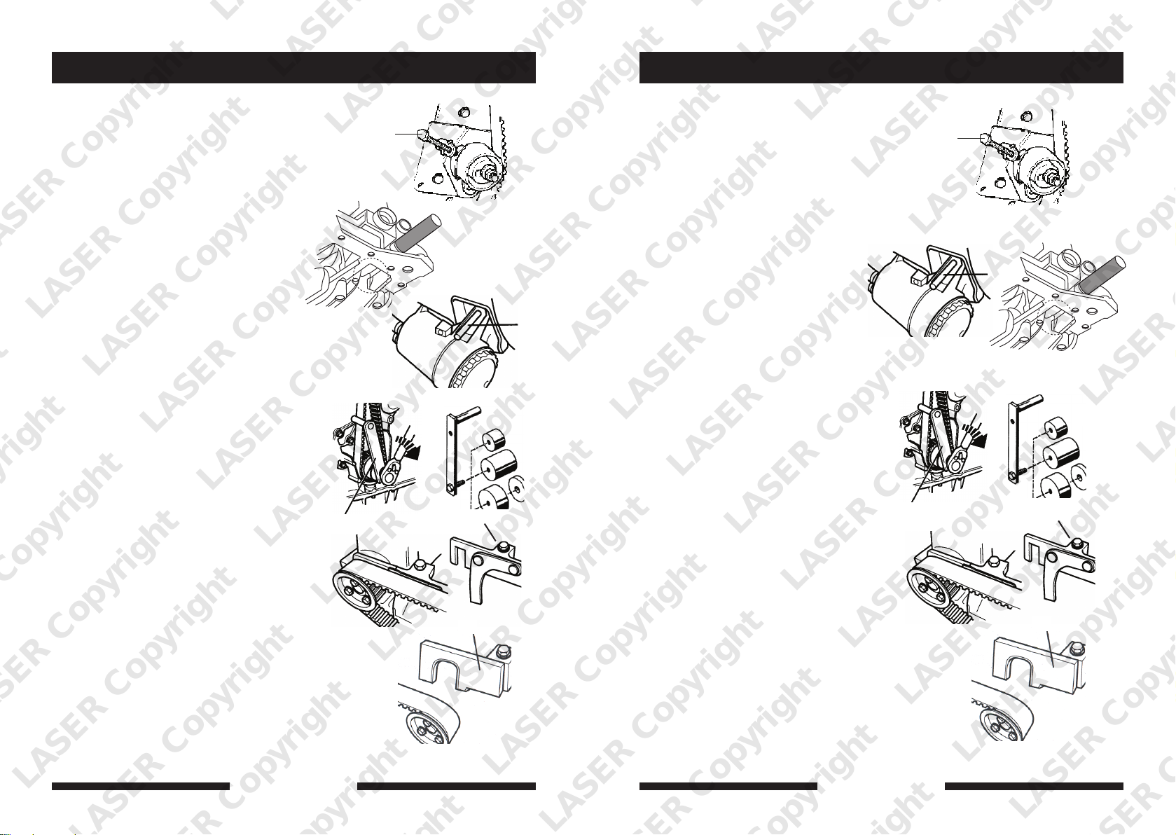
Instruction (GB)
A
A
Instruction (FR)
Tensioning Adjustment Screw
To enable the correct tension to be applied
to the timing belt.
B
Crankshaft Timing Pins
There are two different pieces included in
this set. As with the camshaft timing pin,
they are inserted through the engine block
and used to position the crankshaft to
achieve the correct timing position of the
first cylinder.
It is important that these pieces are used
to set the timing position, but are not to
be used to lock the flywheel.
A
G
Tensioning Tools
To enable the correct pre-tension to be
applied to the timing belt, this tool has 4
interchangeable covers and a spacing
washer to suit the variety of tensioners
used.
Install the exhaust camshaft locking tool
and hold in place using the setscrew
If the tool cannot be fitted correctly, rotate
the crankshaft one turn clockwise.
Slacken the sprocket fasteners, but check
that during installation the fasteners are
not positioned at the end of the slots.
The lever arm will make contact with the
tensioner. As a visual register the top of
the arm will align with the camshaft
locking tool when the tensioner is turned
anti-clockwise whilst being tensioned
using a 6 mm. hex. key.
Install the inlet camshaft locking tool
over the vertical flats on the camshaft.
H
D
E
Boulon de tendeur
Pour l’application de la tension sur
la courroie de distribution
Piges de calage des
volants moteurs:
Permet le calage du vilebrequin au PMH.
Outil de calage moteur de PMH, à ne pas
utiliser comme outil de blocage moteur.
Outils de tendeur
Permettre à la pre - tension correcte d’être
appliqué à la ceinture du réglage. Cet outil
a trois coupes interchangeables et une
rondelle de l’espacement pour convenir la
variété de tensioner utilisé
Monter l’ outil de calage d’ arbres à cames,
échappement, F et le tenir fixe utilisant la
vis de blocage G.
Si ce n’ est pas possible de monter l’ outil
correctement, tourner le vilebrequin un
tour dans le sens des aiguilles d’ une
montre. Lacher les vis du pignon, mais
contrôler que pendant le montage les vis
ne se trouvent pas aux extremités des
fentes. Le bras levier va contacter la poulie
de tension. Comme répère visuel la partie
supérieure du levier tendeur va s’ aligner
avec l’ outil de blocage de l’ arbre à came
quand la poulie de tension est tourné
anti-horaire en appliquant la tension avec
une clé hexagonale de 6mm.
Monter l’ outil de blocage d’ arbre à came
admission H sur les surfaces plates sur l’
arbre à came.
Mode d’emploi – Il faut toujours se référer
au manuel d’entretien du constructeur
automobile ou à un manuel d’instructions
approprié du constructeur.
B
G
A
E
H
D
LASER Copyright LASER Copyright LASER Copyright LASER Copyright
4
www.lasertools.co.uk
www.lasertools.co.uk
5
 Loading...