

Page 1

Incorrect or out of phase engine timing can result in damage to the valves.
The Tool Connection cannot be held responsible for any damage caused
by using these tools in anyway.
Safety Precautions – Please read
3388
• Disconnect the battery earth leads
(check radio code is available)
• Remove spark or glow plugs to make
the engine turn easier
• Do not use cleaning fluids on belts,
sprockets or rollers
• Always make a note of the route of the
auxiliary drive belt before removal
• Turn the engine in the normal direction
(clockwise unless stated otherwise)
• Do not turn the camshaft, crankshaft or
diesel injection pump once the timing
chain has been removed (unless
specifically stated)
• Do not use the timing chain to lock the
engine when slackening or tightening
crankshaft pulley bolts
• Do not turn the crankshaft or camshaft
when the timing belt/chain has been
removed
• Mark the direction of the chain before
removing
• It is always recommended to turn the
engine slowly, by hand and to re-check
the camshaft and crankshaft timing
positions.
• Crankshafts and Camshafts may only be
turned with the chain drive mechanism
fully installed.
• Do not turn crankshaft via camshaft or
other gears
• Check the diesel injection pump timing
after replacing the chain
• Observe all tightening torques
• Always refer to the vehicle
manufacturer’s service manual or a
suitable proprietary instruction book
• Incorrect or out of phase engine timing
can result in damage to the valves
• It is always recommended to turn the
engine slowly, by hand, and to re-check
the camshaft and crankshaft timing
positions
Part No. 3581
Opel | Vauxhall | Saab
LASER Copyright LASER Copyright LASER Copyright LASER Copyright
LASER Copyright LASER Copyright LASER Copyright LASER Copyright
www.lasertools.co.uk
www.lasertools.co.uk
LASER Copyright LASER Copyright LASER Copyright LASER Copyright
Page 2
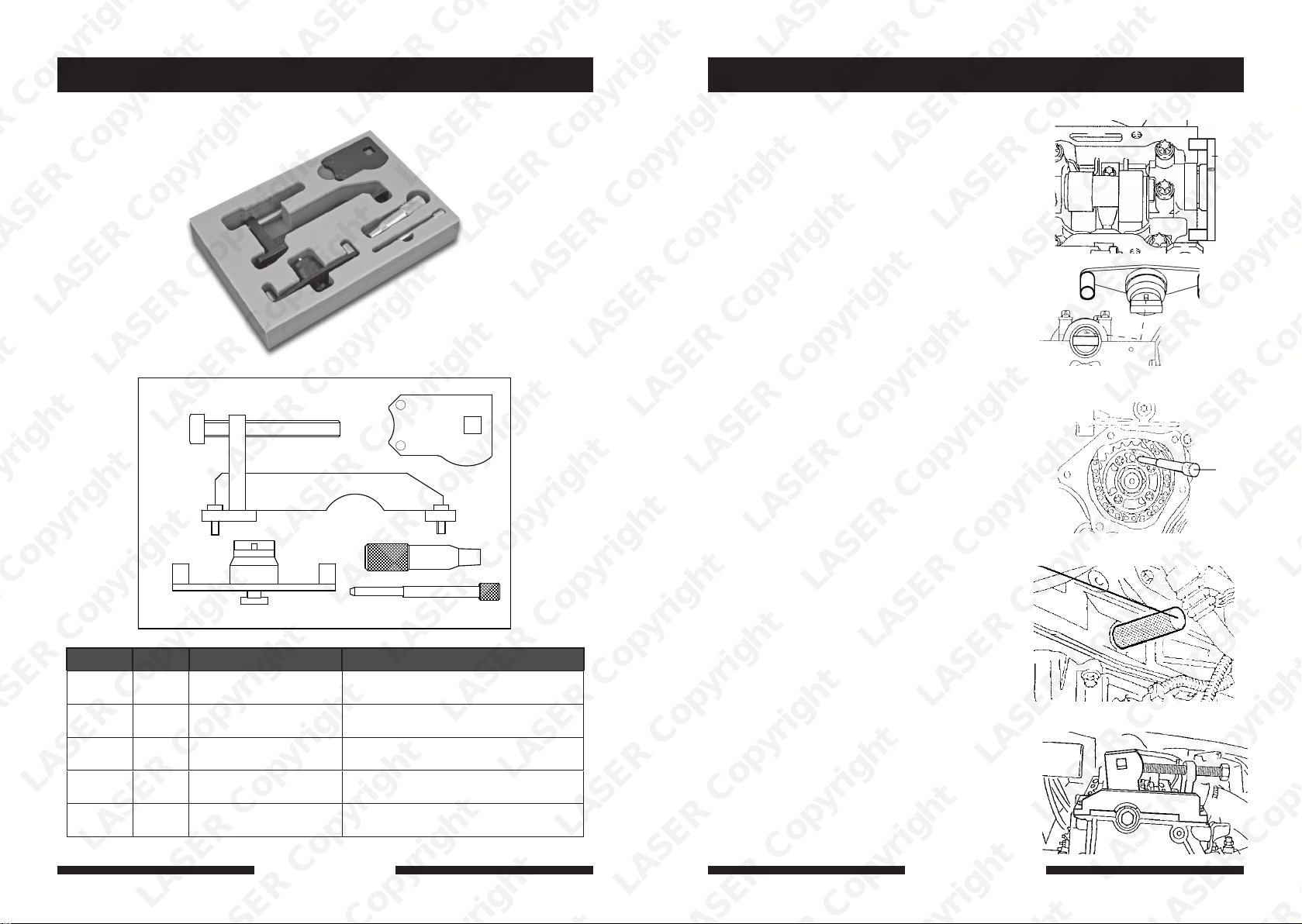
Plan Layout Instruction (DE)
Die richtige Motorsteuerungsstellung wird
erreicht, wenn sich der erste Zylinder bei OT
befindet und jedes der Einstellwerkzeuge
richtig eingesetzt werden kann.
1. Die Nockenwelle wird waagerecht mit
Passloch oben positioniert. Das
Nockenwellen-Einstellwerkzeug (E) zum
Ausrichten der Nockenwelle verwenden
(siehe Abb. 1).
2. Der Einspritzpumpen-Einstellstift (C)
fluchtet mit einer Einstellmarkierung am
Kettenrad und wird durch eine
Aussparung im Einspritzpumpenflansch
und die Befestigungsbohrung gesteckt.
(siehe Abb. 2)
3. Der Kurbelwellen-Fixierdorn (D) wird
zum Einstellen der Kurbelwelle in der
OT-Stellung verwendet. Dieses Werkzeug
wird durch die Öffnung für den
A
B
D
E
C
Ref Code Oem Code Description
A C169
B
LASER Copyright LASER Copyright LASER Copyright LASER Copyright
C
D
E
C170
C171
C172
C173
KM-933
83 95 394
KM-933
83 95 394
KM-927
83 95 337
KM-929
83 95 352
KM-932
83 95 386
Timing Adjustment Wrench
Timing Adjustment Bracket Assembly
Injection Pump Timing Pin
Crankshaft TDC Setting Pin
Camshaft Setting Plate
LASER Copyright LASER Copyright LASER Copyright LASER Copyright
2 7
LASER Copyright LASER Copyright LASER Copyright LASER Copyright
www.lasertools.co.uk
Kurbelwellen-Impulsaufnehmer im
Motorblock eingesteckt und sitzt in
einem Schlitz in der Kurbelwelle. (siehe
Abb. 3)
4. Das Einstellwerkzeug für das
Einspritzpumpen-Kettenrad- (A+B)
ermöglicht eine Einstellung der richtigen
Motorsteuerungsstellung durch
Maßnahmen an der Simplex-Kette und
dem Nockenwellenrad. Zuerst den
Doppelzapfenschlüssel vertikal am
Kettenrad anbringen, dann das
Hilfswerkzeug am Zylinderkopf
befestigen. Mit einem
½”-Vierkantschrauber einen geringen
Druck zum Drehen der Nockenwelle im
Gegenuhrzeigersinn anwenden (gegen
die Motordrehrichtung). Die Schraube
wird dann gedreht, bis sie den
Doppelzapfenschlüssel berührt, und in
dieser Stellung belassen. (siehe Abb. 4)
5. Jetzt muss der EinspritzpumpenFixierdorn (C) locker sitzen und entfernt
und wieder eingesteckt werden können.
Wenn dieser Dorn fest sitzt, die Schraube
einstellen, bis sich der Dorn leicht
entfernen lässt. Die Schraube des
Nockenwellenrads kann jetzt festgezogen
und der Simplex-Ketten-Spanner wieder
montiert werden.
www.lasertools.co.uk
Fig. 1
E
C
Fig. 3
D
Fig. 4
A + B
Page 3
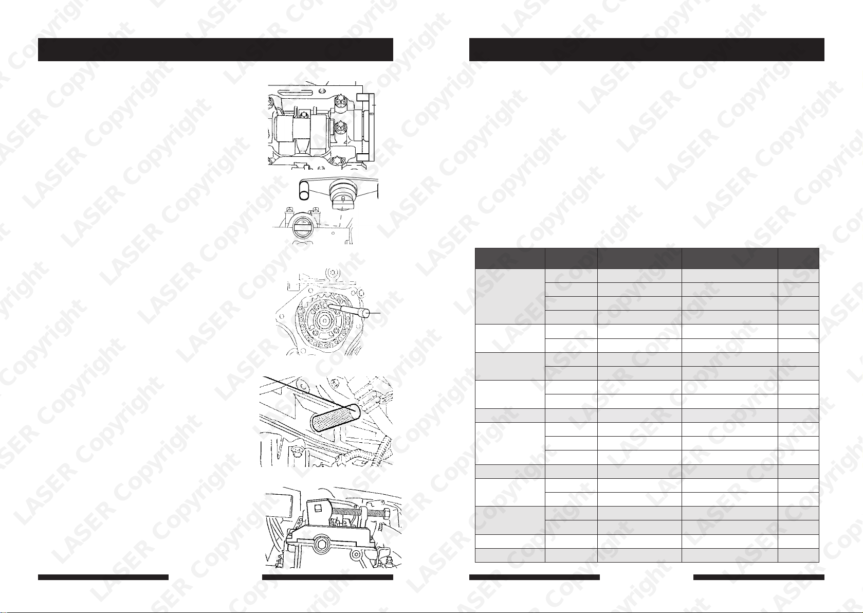
Instruction (ES)
Applications
La posicion correcta se consigue cuando el
primer cilindro esta a su punto muerto
superior y cada una de las herramientas se
pueden montar correctamente.
1. El árbol de levas se posiciona
horizontalmente con el agujero de
locación arriba. Use la placa (E) para
alinear el árbol de levas.
2. El pasador de la bomba (C) se alinea
con una señal de calado en el piñon y
se coloca dentro del agujero de
retención. Ver fig. 2.
Fig. 1
E
Fig. 2
3. El pasador de cigüeñal (D) se usa para
posicionar el cigüeñal a su punto
muerto superior. Se coloca en una
ranura del cigüeñal a través del
bloque del motor.
4. La llave (A) y util (B) facilita la
posición correcta a través del piñon
del árbol de levas y la cadena simplex.
Primero coloque la llave (A)
verticalmente al piñon y después el
util (B) al cilindro. Utilizando una
llave de carraca de 1/2” gire
ligeramente el árbol de levas en
sentido contrario a las agujas del
reloj. Gire el tornillo para hacer
contacto con la llave (A) y mantener
esta posición. (ver fig.4).
5. El pasador (C) debe estar suelto. Si no
se mueve con facilidad, ajuste el
LASER Copyright LASER Copyright LASER Copyright LASER Copyright
6
tornillo hasta que se mueva
libremente.
El piñon del árbol de levas se puede
apretar y el tensor de la cadena
simples remontado.
LASER Copyright LASER Copyright LASER Copyright LASER Copyright
www.lasertools.co.uk
LASER Copyright LASER Copyright LASER Copyright LASER Copyright
Fig. 3
D
Fig. 4
A + B
C
The application list for this product has been compiled cross referencing the OEM Tool Code
with the Component Code.
In most cases the tools are specific to this type of engine and are necessary for Cam belt or
chain maintenance.
If the engine has been identified as an interference engine valve to piston damage will occur
if the engine is run with a broken Cam belt.
A compression check of all cylinders should be performed before removing the cylinder head.
Always consult a suitable work shop manual before attempting to change the Cam belt or
Chain.
The use of these engine timing tools is purely down to the user’s discretion and
Tool Connection cannot be held responsible for any damage caused what so ever.
ALWAYS USE A REPUTABLE WORKSHOP MANUAL
Manufacturer Model Style Engine Code Year
Opel | Vauxhall
Opel | Vauxhall
Opel | Vauxhall
Opel | Vauxhall
Opel | Vauxhall Sintra 2.2 | Turbo | D X22DTH 1998-99
Opel | Vauxhall
Opel | Vauxhall Vectra-B 2.2 | DTi | D Y22DTR 2000-02
Opel | Vauxhall
Opel | Vauxhall
Opel | Vauxhall Zafira-A 2.2 | DTi | D Y22DTR 2002-05
Saab 9-3 2.2 | DTi | D D223L 1998-06
Astra-G 2.0 | DTi | D X20DTL 1998-02
Frontera-B 2.2 | DTi | D X22DTH 1998-01
Omega-B 2.0 | DTi | D X20DTH 1998-00
2.2 | DTi | D Y22DTH 2000-03
Signum 2.0 | DTi | D Y20DTH 2003-05
2.2 | DTi | D Y22DTR 2003-05
Vectra-B 2.0 | DTi | D X20DTH 1997-00
Vectra-C 2.0 | DTi | D Y20DTH 2002-05
DTi | D Y22DTR 2002-05
Zafira-A 2.0 | DTi | D X20DTL 1999-00
DTi | D Y20DTH 2003-05
www.lasertools.co.uk
Y20DTH 1999-05
Y20DTL 2000-05
Y22DTR 2000-06
Y22DTH 2000-04
X20DTL 2000-00
Y20DTH 2000-02
3
Page 4
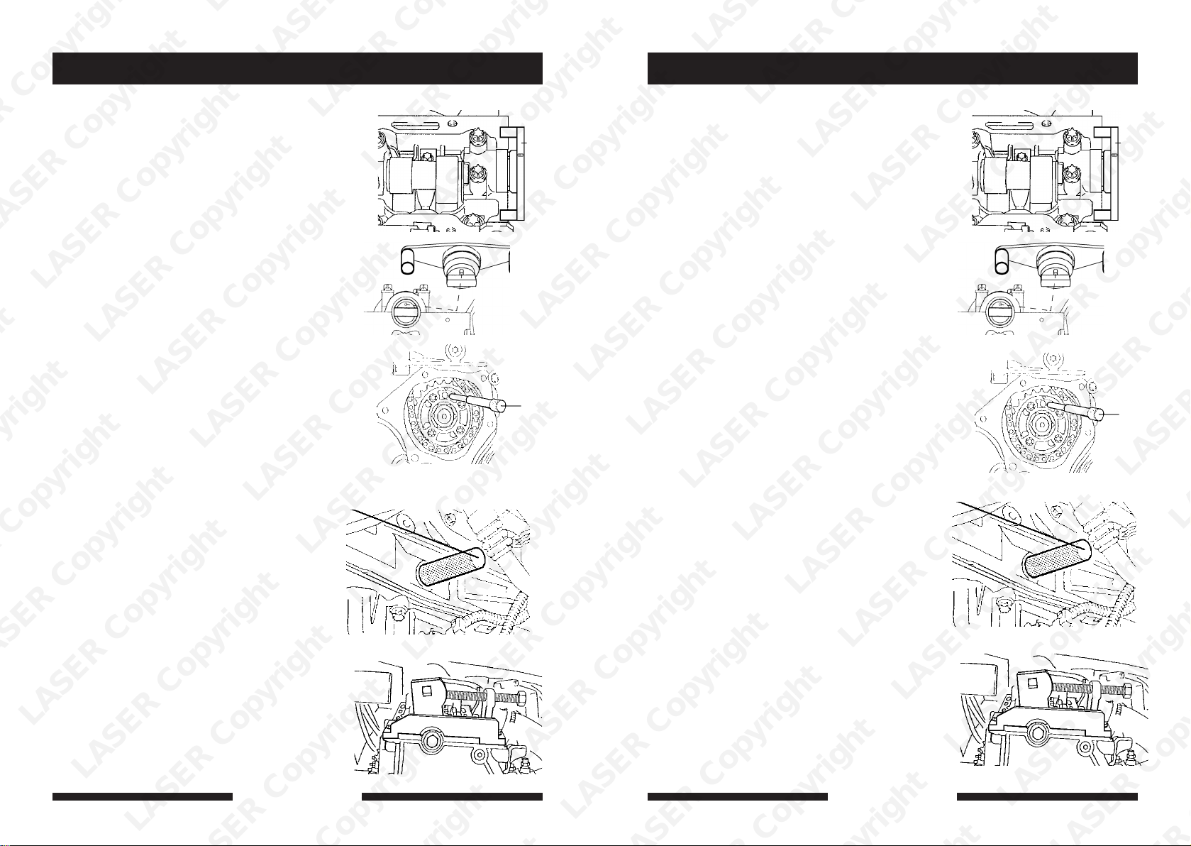
Instruction (FR)Instruction (GB)
The correct engine timing position is
achieved when the first cylinder is at TDC
and each of the timing tools can be
correctly fitted.
1. The camshaft is positioned
horizontally with the location hole at
the top. Use the camshaft setting tool
(E) to align the camshaft (see Fig.1)
2. The Injection Pump Setting Pin (C)
aligns to a timing mark on the
sprocket and is fitted through a recess
in the injection pump flange and into
the retaining hole. (see Fig.2)
3. The crankshaft locking pin (D) is used
to set the crankshaft at TDC position.
This tool is fitted through the
crankshaft pulse pick-up opening in
the engine block and locates into a
slot in the crankshaft. (see Fig.3)
4. Fuel Pump Sprocket Timing Tool
(A+B) enables the correct timing
position through action to the simplex
chain and camshaft sprocket. First
attach the special wrench vertically to
the sprocket, then attach the bracket
assembly to the cylinder head. Using a
½” Sq.
Dr. wrench to apply light pressure to
turn the camshaft in an anti-clockwise
(contra-engine rotation). The screw is
the turned to contact the special
wrench and retain this position. (see
Fig.4)
5. At this stage the Pump Locking Pin (C)
should be free to be removed and
LASER Copyright LASER Copyright LASER Copyright LASER Copyright
4 5
re-fitted. If this pin is tight, adjust the
screw until the pin is easy to move.
The camshaft sprocket bolt can now
be tightened and refit the simplex
chain tensioner.
LASER Copyright LASER Copyright LASER Copyright LASER Copyright
www.lasertools.co.uk www.lasertools.co.uk
LASER Copyright LASER Copyright LASER Copyright LASER Copyright
Fig. 1 Fig. 1
E E
Fig. 2
C
Fig. 3
D
Fig. 4
A + B
La position de calage correcte du moteur est
obtenue lorsque le premier cylindre est au
PMH et que chacun des outils de calage peut
être installé correctement.
1. L’arbre à cames est positionné
horizontalement avec l’orifice de
positionnement sur le haut. Utiliser l’outil
de blocage de l’arbre à cames (E) pour
aligner l’arbre à cames (voir la Fig.1)
2. La cheville de réglage de la pompe à
injection (C) s’aligne sur un repère de
calage de la roue dentée et elle est
insérée à travers un logement de la bride
de la pompe à injection et dans l’orifice
de fixation. (voir la Fig.2)
3. La cheville de blocage du vilebrequin (D)
est utilisée pour bloquer le vilebrequin
dans la position PMH. Cet outil est installé
à travers l’ouverture du capteur
d’impulsions du vilebrequin dans le bloc
moteur et il s’insère dans une encoche du
vilebrequin. (voir la Fig.3)
4. L’outil de calage de la roue dentée de la
pompe à carburant (A+B) permet
d’obtenir la position de calage correcte
par action sur la chaîne simplex et la roue
dentée de l’arbre à cames. Poser d’abord
verticalement la clé spéciale sur la roue
dentée, puis poser l’ensemble support sur
la culasse. A l’aide d’une clé à carré
conducteur de ½”, exercer une légère
pression pour faire tourner l’arbre à
cames dans le sens anti-horaire (sens
inverse à celui de la rotation du moteur).
La vis tourne jusqu’en butée avec la clé
spéciale et elle reste dans cette position.
(voir la Fig.4)
À ce moment-là, la cheville de blocage de
la pompe (C) peut être déposée et
réinstallée librement. Si cette cheville est
serrée, ajuster la vis jusqu’à ce que la
cheville puisse bouger facilement. Le
boulon de la roue dentée d’arbre à cames
peut maintenant être serré et le tendeur
de la chaîne simplex réinstallé
Fig. 2
Fig. 3
D
Fig. 4
A + B
C
 Loading...