

Page 1
Part No. 3388
Engine Timing Tools
Renault Twin Cam 16v
www.lasertools.co.uk
www.lasertools.co.uk
Page 2
Plan Layout
C
A
B
D
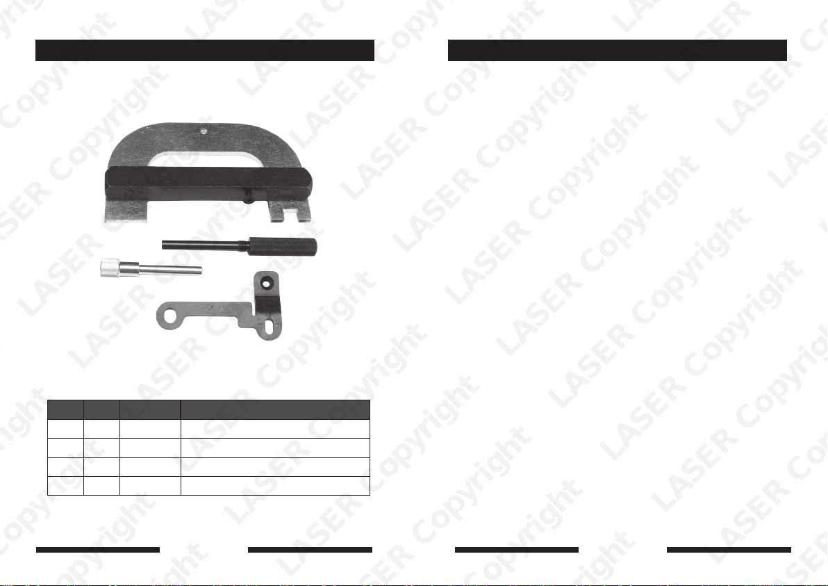
Ref Code Oem Ref Description
A C037 Mot 1489 Crankshaft Timing Pin
B C099 Mot 1054 Crankshaft Timing Pin
C C120 Mot 1496 Camshaft Setting Bar
D C402 Mot 1750 Mounting Bracket
www.lasertools.co.uk
2
www.lasertools.co.uk
7
Page 3
Plan Layout
Applications
Incorrect or out of phase engine timing can result in damage to the valves.
The Tool Connection cannot be held responsible for any damage caused
by using these tools in anyway.
Safety Precautions – Please read
• Disconnect the battery earth leads
(check radio code is available)
• Remove spark or glow plugs to make
the engine turn easier
• Do not use cleaning fluids on belts,
sprockets or rollers
• Always make a note of the route of the
auxiliary drive belt before removal
• Turn the engine in the normal direction
(clockwise unless stated otherwise)
• Do not turn the camshaft, crankshaft or
diesel injection pump once the timing
chain has been removed (unless
specifically stated)
• Do not use the timing chain to lock the
engine when slackening or tightening
crankshaft pulley bolts
• Do not turn the crankshaft or camshaft
when the timing belt/chain has been
removed
• Mark the direction of the chain before
removing
• It is always recommended to turn the
engine slowly, by hand and to re-check
the camshaft and crankshaft timing
positions.
• Crankshafts and Camshafts may only be
turned with the chain drive mechanism
fully installed.
• Do not turn crankshaft via camshaft or
other gears
• Check the diesel injection pump timing
after replacing the chain
• Observe all tightening torques
• Always refer to the vehicle
manufacturer’s service manual or a
suitable proprietary instruction book
• Incorrect or out of phase engine timing
can result in damage to the valves
• It is always recommended to turn the
engine slowly, by hand, and to re-check
the camshaft and crankshaft timing
positions
The application list for this product has been compiled cross referencing the OEM Tool
Code with the Component Code.
In most cases the tools are specific to this type of engine and are necessary for Cam belt
or chain maintenance.
If the engine has been identified as an interference engine valve to piston damage will
occur if the engine is run with a broken Cam belt.
A compression check of all cylinders should be performed before removing the cylinder
head.
Always consult a suitable work shop manual before attempting to change the Cam belt
or Chain.
The use of these engine timing tools is purely down to the user’s discretion and
The Tool Connection cannot be held responsible for any damage caused what so ever.
ALWAYS USE A REPUTABLE WORKSHOP MANUAL
Manufacturer Model Engine Code Year
Clio | Clio lll 1.4 | 1.6
Mégane | Scenic 1.6
Laguna 1.6
Clio Sport 2.0
Mégane | Scenic 2.0
Laguna 1.8 | 2.0
Espace 2.0
K4J 712 | 713 | 750
K4M 700 | 701 | 720
724 | 748
F4P | 760 | F4R | 700
701 | 730 | 740 | 741 | 780
2003
1998
1998
1998
1998
1998
1998
www.lasertools.co.uk
6
www.lasertools.co.uk
3
Page 4
Instruction 1.4 | 1.6 16v
Removal
1. Raise and safely support the front of
the car.
2.
Remove the engine top cover
hand splash guard and auxilliary
drive belt.
Safely support the engine.
3.
4.
Remove the right hand side engine
mounting, blanking plugs from rear
of camshafts, blanking plug from
cylinder block.
Lock flywheel and slacken the
5.
crankshaft pulley bolt.
6.
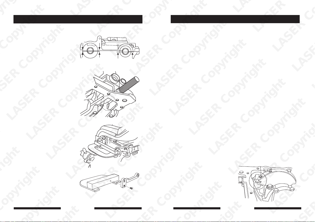
Rotate crankshaft clockwise to the
setting position ensuring that the
grooves in the camshaft align.
The grooves are positioned below
the upper face of the cylinder head.
(Fig 1.)
7.
Insert the Crankshaft T
to locate against the crankshaft web.
(Fig 2.)
Fit the Camshaft Setting Bar
8.
to rear of the camshafts. (Fig 3)
9.
Remove the crankshaft pulley bolt,
crankshaft pulley and timing belt
covers.
Slacken the tensioner nut.
10.
11.
Move the tensioner pulley away
from the timing belt.
4
, right
iming Pin (A)
(C)
www.lasertools.co.uk
Fig. 1
Fig. 2
Fig. 3
Fig. 3a
Instruction
Installation
1. Check that the Crankshaft Timing Pin
is still correctly fitted and contacting
the crankshaft web.
Check that the Camshaft Setting Bar is
2.
still correctly fitted and the grooves in
the camshaft are aligned
Fit guide pulley and tighten to 45Nm.
3.
4.
Fit the tensioner pulley and finger
tighten, ensuring that the lug on rear
of the pulley is located in the groove
in the cylinder head.
Remove and de-grease the crankshaft
5.
sprocket and the mating end of the
crankshaft.
Note:
Double check crank position by ensuring
the crankshaft key is a t 12 0 Clock
Fit the new timing beltin an
6.
anti-clockwise direction, starting at
the crankshaft sprocket. Check that
the belt is taut on the non-tensioned
side.
Refit the crankshaft pulley using a
7.
new bolt, leaving 2-3 mm. clearance
between bolt face and pulley
8.
Slacken the tensioner nut and using a
mm. hexagon key, turn the tensioner
6
pulley clockwise until the pointer is at
the right hand stop. The moveable
pointer should be 7-8 mm. past the
fixed pointer.
9.
Lightly tighten the tensioner nut to 7
Nm.
Lock the flywheel and increase the
10.
tensioner nut tightness to 20 Nm,
Remove both timing tools.
11.
With the flywheel locked tighten the
12.
crankshaft pulley bolt by 120-150°.
Use Angular Torque Gauge 2245.
13.
Rotate the crankshaft two full turns
clockwise back to the setting position.
.
www.lasertools.co.uk
Re fit the Crankshaft Timing Pin to
14.
correctly contact the crankshaft web
and check that the Camshaft Setting
Bar can be easily fitted.
Hold the tensioner pulley using the 6
15.
mm. hexagon key and slacken the
tensioner nut.
16.
Turn the tensioner pulley anti-
clockwise until the pointers align and
tighten the tensioner nut to 27 Nm.
17.
Remove both timing tools and refit the
blanking plug.
Fit new blanking plugs to the rear of
18.
the camshafts.
Reinstall the remaining parts in reverse
19.
order of removal.
Instruction 1.8 | 2.0 16v
The proceedures for removing and installing
timing belts on these engines is similar to
those detailed above, but the Crankshaft
Timing Pin is different. Use part (B) This Pin
must be fitted into the slot in the crankshaft
web. (Fig. 4)
This Pin must NOT be fitted into the balance
hole.
Double check crank position by ensuring the
crankshaft key way is aligned centrally
between the casting lugs on the front of
the engine. (Approximately 1 0 Clock
position)
Fig. 4
5
 Loading...