

LASDROP Gen.II Installation Instructions Manual
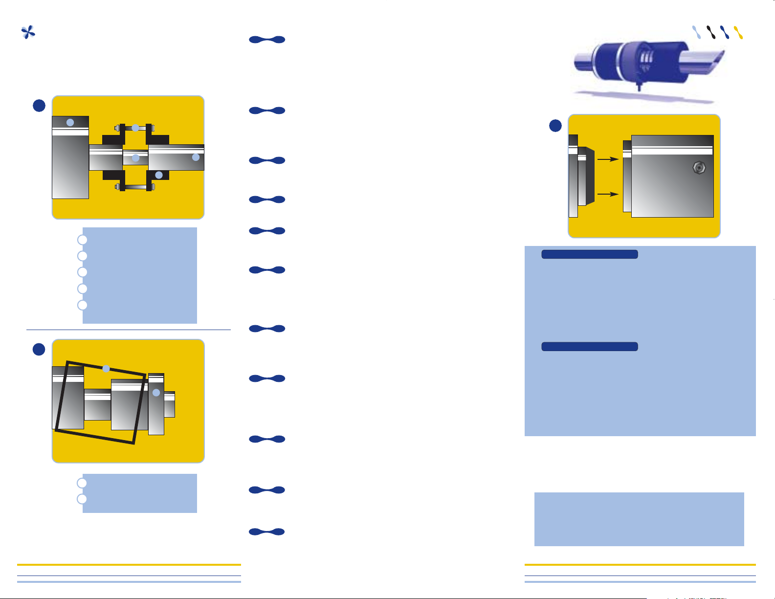
Unbolt the shaft coupling from the engine coupling.Remove the
shaft coupling from the shaft (on most installations the coupling
is held on the shaft by two set screws). Helpful hint: Removing
the shaft coupling may be difficult. The drawing below shows
the use of a spacer as a press between propeller shaft and the
transmission(fig.1)
Insert a spacer (smaller than the shaft diameter) between the
shaft and transmission.Re-tighten the coupling back onto the
transmission. You have now created a press to push the shaft
away from the coupling.
Remove your old stuffing box. (*If your boat is equipped with a
bolt on or rigid type stuffing box, please refer to heading: For
bolt-on or rigid type stuffing boxes.)
Clean shaft as thoroughly as possible with very fine sandpaper
(400 to 600 grit) and remove any sharp edges or burrs.
Slide the Friction Assembly over the shaft and connect it to your
stern tube with the provided stainless hose clamps. An insert
may be necessary for proper fit.
When mounting Friction Assembly, arrange connection hose so
that there is a minimum amount of pressure on the inner alignment bearing (inside the Friction Assembly). This should only
have to be done if shaft is not centralized with the stern tube in
a fairly extreme manner.
Mount connection hose crooked to relieve any major pressure
caused by misalignment. When tightening hose to Friction
Assembly with clamps, DO NOT over tighten. This may cause
Friction Assembly to grab shaft(Fig.2)
If the end of your drive shaft is not tapered, you will need to use
the included installation plug to install the Clamp/Pressure unit
over the shaft. Use liquid soap to lubricate the inner lip seals
then place the installation plug next to the lip seal inside the
unit.
Carefully slide the Assembly onto the shaft. You will need to
push the plug out the back of the Assembly using your finger as
a guide. Re-install the coupling onto the shaft and bolt the
assembly back onto the transmission.
Slide the Clamp/Pressure assembly into contact with the carbon
friction assembly and mark this “neutral” position with a magic
marker(Fig.3)
While using the “neutral” mark on the shaft, compress the
Clamp/Pressure assembly 1/4”. Keeping the assembly onto the
shaft by tightening the two bolts on the housing.
1111
1100
55
66
77
88
99
44
33
11
22
RRee aa dd AAllll IInn sstt rr uucc ttiioonnss tt hhoorr oo uu gghh llyy bbee ffoorree iinn sstt aall ll iinngg
tthh ee LL aa ssddrr oo pp GGeenn.. IIII.. BBee SSuurree nnoott ttoo ddaammaaggee tthh ee
iinnnnee rr ll ii pp ssee aa ll wwhhiillee uu nn pp aa cc kkiinn gg aa nn dd hhaa nn ddlliinngg..
AA
BB
CC
DD
EE
AA
BB
CC
DD
EE
Transmission
Bolt
Spacer
Shaft Coupling
Shaft
AA
BB
AA
BB
Friction Assembly
Mounting Hose
Drawing is exaggerated for demonstration purposes
HHuullllss AABBOOVVEE 1100 KKnnoottss
HHuullllss BBEELLOOWW 1100 KKnnoottss
The Lasdrop Gen.II. requires water for cooling and lubrication.
The system uses a “vent line” that lets air escape from the seal
and stern tube to let water take its place. Simply route the
included hose above the water line. A valve can also be spliced
into the line and used as a safety shut off. Whenever launching
your boat, open the valve and “burp” the system.
High speed hulls must inject water into the seal. The supply to
the after-cooler, a bottom hull scoop or separate water pump are
good sources for cool clean water. It is best that the supply line
is spliced into a fresh water line using a “T” fitting. (Due to the
many different combinations of “T” sizes, this part is not included in the kit.) The exhaust manifolds may also provide water,
but due to the excess heat of some boats and the amount of
floating debris, it is not recommended.
WWaarrnniinngg!!
If engine is located below water line, DO NOT connect water coolant
line into exhaust manifold.This may flood the engine.
11
22
33
IIMMPPOORRTTAANNTT!!
There is, on average, a 20 minute break-in period when the
carbon face is polishing the face of the stainless steel.
During this break-in period there will be a fine black mist
being emitted during operation between the two faces.
IInnssttaallllaattiioonn IInnssttrruuccttiioonnss
GGeenn..IIII
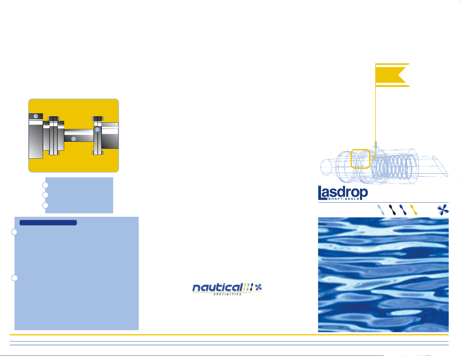
FF OORR BBOO LLTT--OONN OORR RRII GGIIDD SSTTUUFFFF IINNGG BBOO XXEESS::
If your stuffing box is a bolt-on or rigid type you will need to
reverse the plate and tube that are used to compress the
packing. Once reversed, the connection hose can be fitted
over the tube. When re-attaching your reversed plate and
tube, seal the two surfaces so that no water can leak
through. Products such as “Form-a-Gasket” or an automotive type of gasket will work for this application. If your old
stuffing box was threaded on you will need to cover the
threads with a liquid gasket material like “Form-a-gasket” to
prevent the threads from cutting into the connection hose.
AA
Transmission
Shaft
Bolt-on Stuffing box
AA
BB
CC
BB
CC
Every engine, shaft, and motor mounts are different. Because
of this, every installation may be different. If you should experience any spray or “misting” during high speed operation
(after break-in period), add an additional 1/16” compressionto
the Clamp/Pressure assembly and repeat until the spray has
stopped at cruising RPM
The seal is created between the polished faces of the
Stainless steel and the carbon. If the seal leaks when the is
not turning, some foreign material such as grease or transmission fluid may be prohibiting the two faces from seating properly. To clean this foreign material from the two faces, insert a
clean cloth rag between carbon and stainless steel faces and
rotate it around the shaft vigorously. As you do this, water
will flush both faces of any impurities.
TTrroouubblleesshhoooottiinngg
11
22
Spray or “mist” during operation.
Dripping while not operational.
Lasdrop 3-Year Limited Warranty
Nautical Specialties, Inc. hereinafter referred to as NSI,
warrants to the first retail purchase of thisproduct, or a
NSI product, properly incorporated in another venders
products that, for a period of three (3) years from the
date of original purchase, NSI products will be free from
defects in materials and workmanship. NSI makes no
warranty as to merchantability or to fitness of its
products for a particular purpose.
The above warranty does not apply to a product that has
not been installed or maintained in accordance with NSI
instructions, been subject to damage in an accident or
abused during operation, or repaired or modified by persons other than NSI. This warranty is also void when NSI
products are installed at any location which is judged by
NSI to be an inappropriate application which is in NSI
judgement are compatible with the NSI product or
adversely affect its performance or durability.
If any NSI product is used commercially, for such purposes as rental or other income-producing activities,
than this warranty is limited to one (1) year from the date
of original purchase.
NSI’s responsibility in respect to warranty claims is
limited solely to repair or replacement of product found
by NSI to be defective. NSI does not pay for labor
charges connected with removal of a product deemed to
be defective or with installation or replacement of
repaired product, or for any other incidental or
consequential damages resulting from product failure.
To make claim under this warranty, return the product
believed to be defective to Nautical Specialties, Inc.
14081 Timberview Shelby Twp. MI. 48315 along with
proof of purchase. If found to be defective, and if within
the warranty period, NSI will repair or replace the
and return it freight prepaid.
This warranty is and shall be in lieu of all other
warranties, whether expressed or implied by NSI, its
agents, employees, representatives or otherwise with
respect to any sale, service or other transaction on or
subsequent July 20, 1999.
Nautical Specialties Inc.
P.O. Box 223
New Baltimore, MI 48047
USA
toll free - 1 800 940 7325
direct - 586 725 2230
fax - 586 725 2250
 Loading...