

Page 1
Quick Start Guide
Your fastest route to a graphics display
PanelPilot
Page 2
Thank you for buying a PanelPilot compatible
display. This quick start guide provides the basic
information on the use of your product.
Getting to know your display
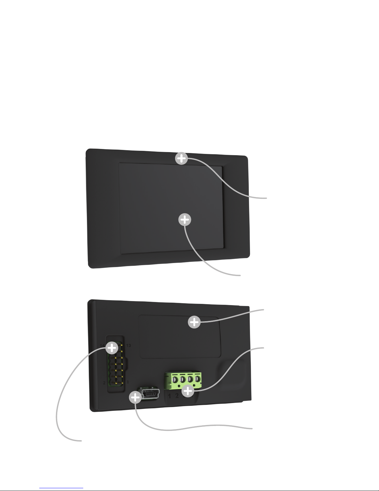
All PanelPilot compatible displays share the following features:
TFT/touch screen
Screw terminal
connections
Mini B USB
type connector
DIL connector
Back plate
Mounting bezel
Page 3
Getting Started
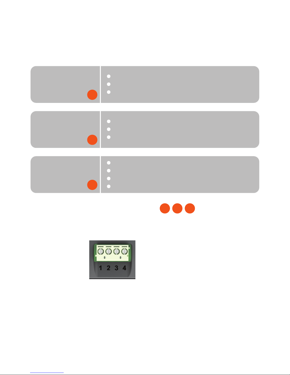
Use the table below to determine which type of user you are,
then follow the steps that follow to get started:
Screw Terminal Connection
There are four screw terminal for connecting single and dual
input applications. They are labelled 1 to 4 as follows:
1 IN2
2 IN1
3 0V
4 V+
N.B. For safety reasons, the meter should be isolated from
both the supply and signal voltages before connecting the USB.
B I A
Basic
User
Pre-configured display - no software install
Connect to application using screw terminals
Mount in panel
Intermediate
User
Advanced
User
Use software to configure and customise display
Connect to application using screw terminals
Mount in panel
Use software to configure and customise display
Utilise advanced display features (I/O)
Connect to application using DIL
Mount in panel
B
I
A
Page 4
Default Configuration
Each display is supplied pre-configured as a 0 to 10V d.c.
single-ended combined analogue and digital voltmeter.
Connection should be made via the screw terminals as follows:
1 IN2 No connection
2 IN1 Connect to 0 to 10V d.c. signal voltage
3 0V Connect to 0V
4 V+ Connect to 4 to 30V d.c. supply voltage
Please consult the Applications section of the appropriate data
sheet for further details of wiring schemes, cautions, etc.
USB connection
Each display features a mini-B USB type connector. By
connecting your display to a PC’s USB port, you can select a
configuration and customise this to your needs. It can then be
downloaded to your display for use in your application.
Download and Install PanelPilot
1) Visit www.panelpilot.com/downloads/ and click on the
“Download Software” button to begin download.
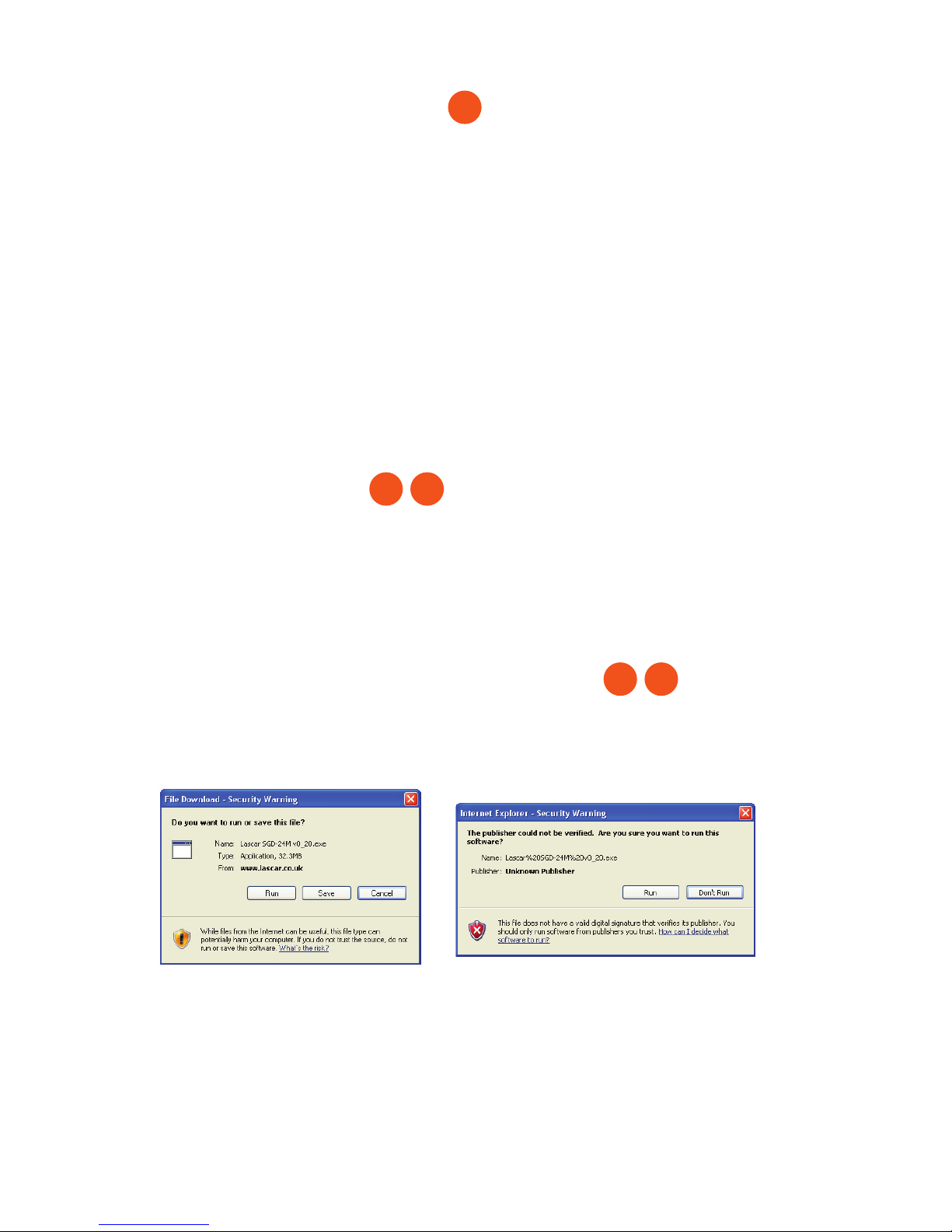
2) When prompted (above left), click “Run” to begin download
and installation.
3) When presented with a Security Warning (above right), click
‘Run’.
I A
I A
B
Page 5
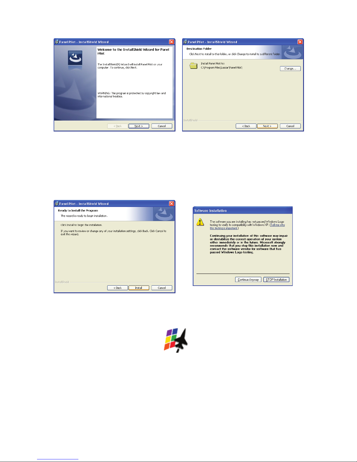
4) At the InstallShield Wizard for PanelPilot screen (shown
above left), click ‘Next’.
5) When prompted choose destination folder (or accept
default) and select ‘Next’ (above right).
6) Click ‘Install’ to begin installation process (above left).
When prompted, click ‘Continue Anyway’ (above right).
7) When installation is complete click ‘Finish’ to quit installer.
You can begin using the PanelPilot software by clicking on
the desktop icon (shown above).
PanelPilot
Page 6
Dual-In-Line IDC
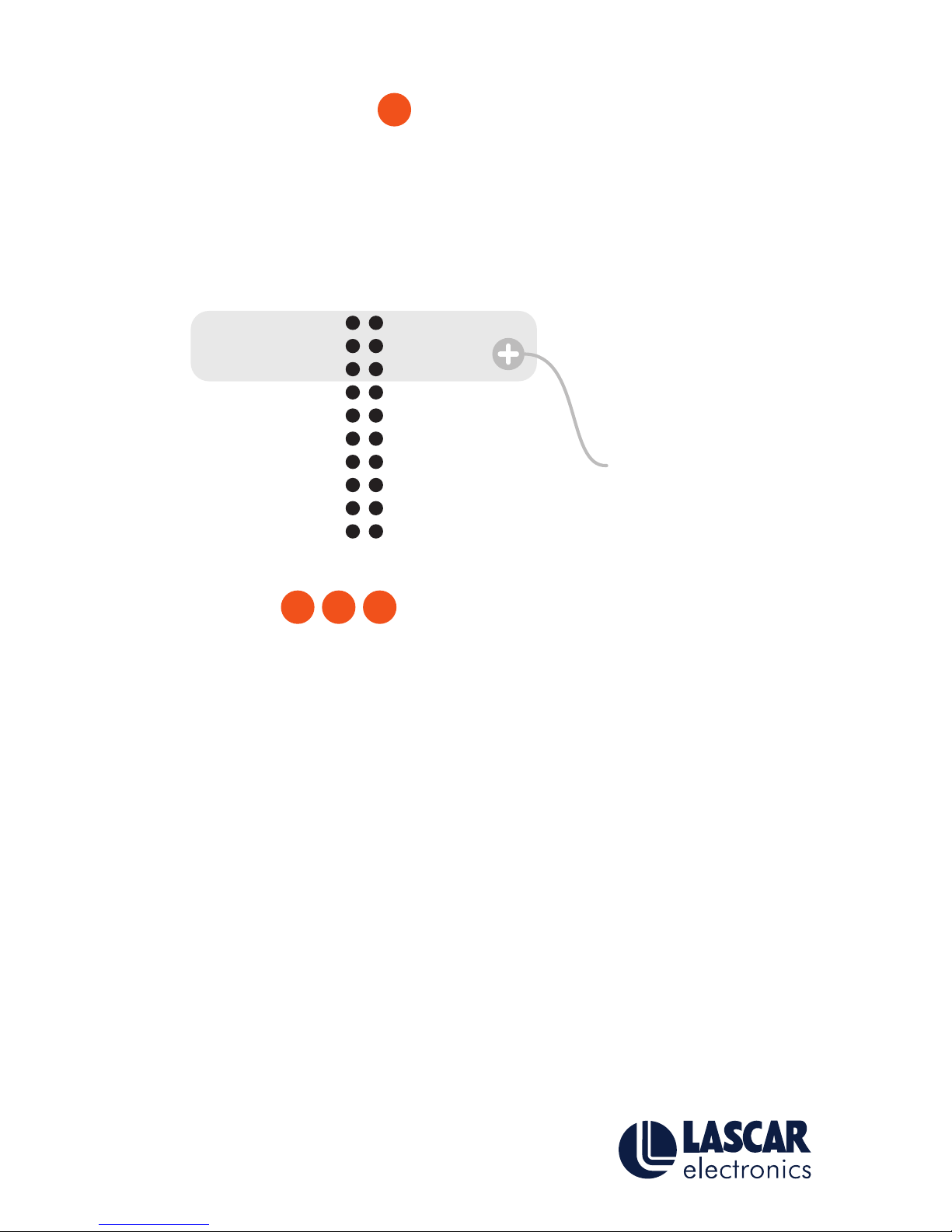
The DIL IDC socket provides an alternative connection method
to the screw-terminals. It also includes provision for future
expansion using data buses and alarm outputs. Visit www.panelpilot.com for information on which features are currently
supported. The pin-out is as follows:
Mounting
Your display can be mounted in a panel up to 3mm deep. We
recommend using the silicone seal provided for panels of 2mm
or less. Please consult the Mounting section of the appropriate
data sheet for exact cut-outs and mounting methods for your
display.
Further Information
Visit www.panelpilot.com for further information on the
PanelPilot platform and to download a datasheet for your
particular display which includes specific information about pin
configurations, wiring instructions and mounting method.
B I A
A
Not fitted on all
display models
N/C
PWM OUT
DAC2
DAC1
SPI-SLCK
SPI-MISO
I²C-SCL
ALM1
0V
IN1
N/C
SPI CS3
3.6V OUT
0V
SPI-MOSI
SPI-CS2
I²C-SDA
ALM2
V+
IN2
Copyright Lascar Electronics Ltd. 2010
Issue 1 27/05/2010
 Loading...