

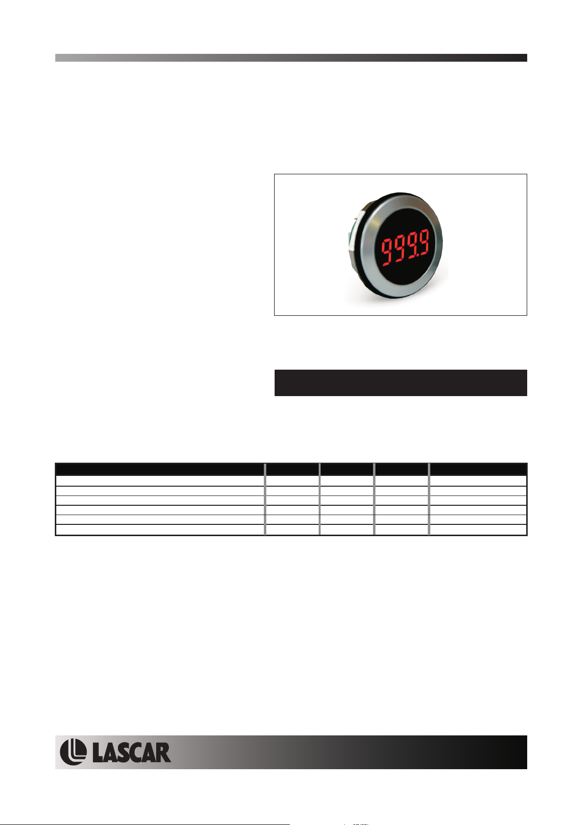
EM32-4B-LED
Round Hole Mounting LED Data Display
The EM32-4B-LED isa4digitLEDdatadisplaywhichisdesignedtobepanelmountedinmostlowandmedium
volume applications. The display features 8mm digit height, 3 decimal points and a very low current
consumption. This product is designed so no soldering is required. Connection is via 2 rows of square posts for
the main functions and the optional external LEDs. The module features a round metal bezel, requiring a
32.5mm (1.28") diameter cut-out. It is secured with the nut provided. Protection from the front to IP 67 / NEMA
4X standardsisachieved by placingthe rubber sealbetween the moduleand panel duringassembly.
FEATURES
•8
mm (0.31") Digit Height
• 20mA @ 5Vd.c. Operation
• Programmable
•
Drives up to 4 External LEDs
• Connection via 2 Rows of Posts
• Round
Metal Bezel
• Requires 32.5mm (1.28") Diameter Cut-out
• IP67 / NEMA 4X Protected
Decimal Points
TYPICAL APPLICATIONS
• Panel Mount Instrumentation
• Process & Control
ORDERING INFORMATION
Stock Number
Standard Display EM32-4B-LED
• Automotive
ELECTRICAL SPECIFICATIONS
Specification Min. Typ. Max. Unit
Supply voltage 4 5 9 V d.c.
Supply current 20* mA
Operating temperature range -10 60 °C
Storage temperature range -10 60 °C
LED
V 3 V d.c.
Clock input frequency 500 kHz
Unless otherwise noted,specificationsapply at T =25°C,V =5Vd.c.
Supply current dependsonsupply voltage, brightnesssettingand number ofLEDsilluminated.
A supply
SAFETY
Tocomply withthe LowVoltage Directive (LVD 93/68/EEC), input voltages to the module’s pins must not exceed
60Vdc. The usermust ensure that theincorporation of the panel meter intothe user ’s equipmentconforms to the
relevant sections of BS EN 61010 (Safety Requirements for Electrical Equipment for Measuring, Control and
Laboratory Use).
LASCAR ELECTRONICS LTD.
MODULE HOUSE
WHITEPARISH
WILTSHIRE SP5 2SJ
UK
TEL: +44 (1794) 884567
FAX: +44 (1794) 884616
E-mail: sales@lascar.co.uk
Specifications liable to change without prior warning EM32-4B-LED Issue Beta2 November/2004 M.C. Applies to EM32-4B-LED/1
LASCAR ELECTRONICS INC.
3750 West 26th Street
Erie
PA 16506
USA
TEL: +1 (814) 835 0621
FAX: +1 (814) 838 8141
E-mail: us-sales@lascarelectronics.com
www.lascarelectronics.com
LASCAR ELECTRONICS (HK) LIMITED
FLAT C, 5/FL., LUCKY FTY. BLDG.
63-65 HUNG TO ROAD
KWUN TONG KOWLOON
HONG KONG
TEL: +852 2797 3219
FAX: +852 2343 6187
E-mail: b4lascar@samsongroup.com.hk
Page2of4Page 2 of 4
Page1of4
EM32-4B-LED
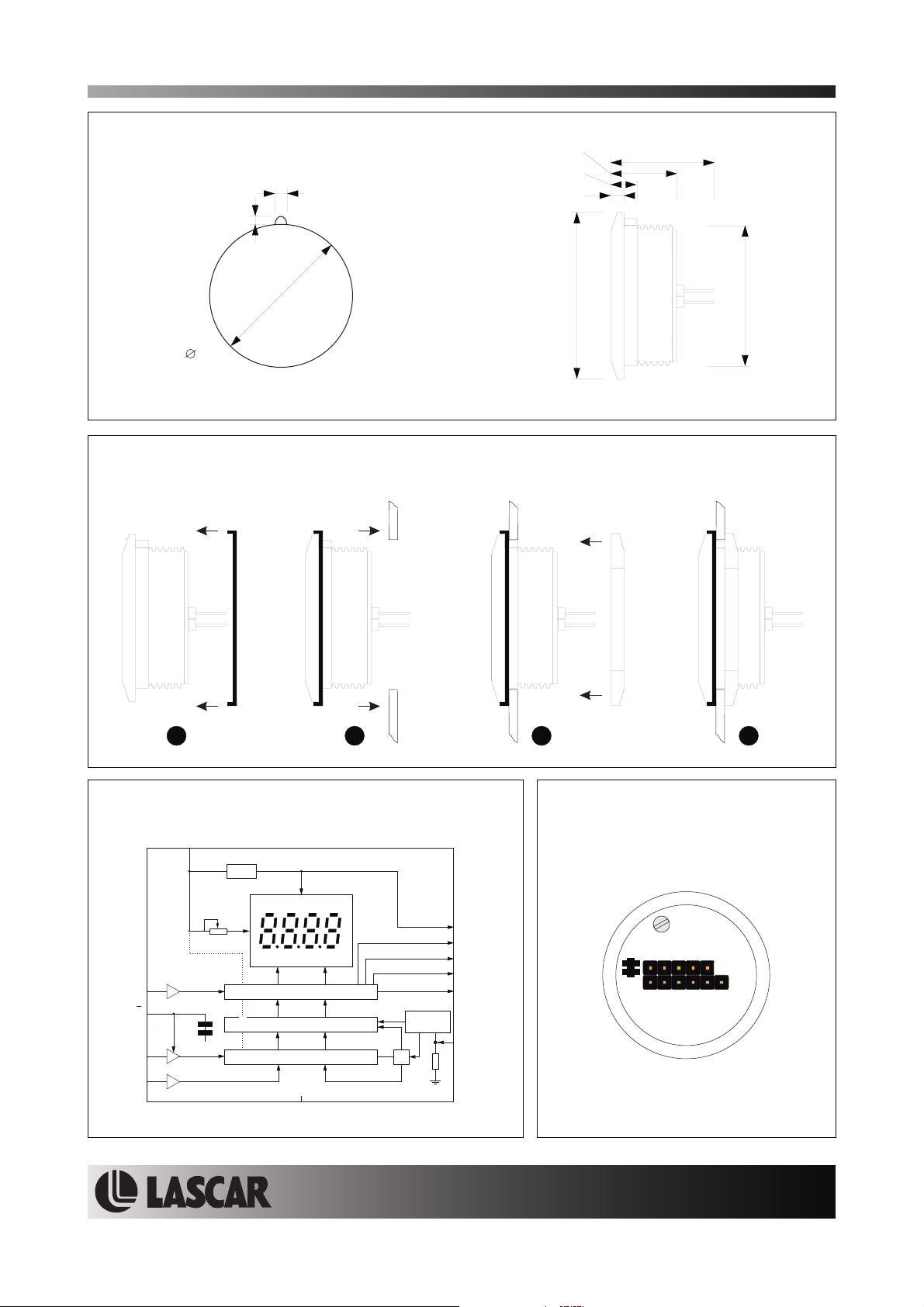
DIMENSIONS
All dimensions in mm (inches)
1.7 (0.07)
1.5 (0.06)
Round Hole Mounting LED Data Display
15.0 (0.59)
5.5 (0.22)
3.0 (0.12)
23.5 (0.93)
32.5
(1.28)
Panel cut-out
PANEL MOUNTING
38.0 (1.5)
32.0 (1.26)
23 41
FUNCTIONAL BLOCK DIAGRAM
V+
Vreg
L
Brightness
......
35 Output Buffers
E
D
Ck
Specifications liable to change without prior warning EM32-4B-LED Issue Beta2 November/2004 M.C. Applies to EM32-4B-LED/1
LE
0V
......
35 Latches
......
35 Bit Shift Register
0V
Power On
Load
Reset
www.lascarelectronics.com
V
L1
L2
L3
L4
Reset
R
CONNECTIONS (rear view)
Brightness
L1 L2 L3 L4 VL
LE
RECkDV+0V
Page2of4
Page2of4Page 2 of 4

EM32-4B-LED
Round Hole Mounting LED Data Display
TIMING
(internal)
(internal)
OUT n
012 3435
Ck
D
Load
Reset
E
R
SERIAL DATA INPUT SEQUENCE
A
F
EC
D
Data is clocked into latches in
reverse order, starting with bit 35
(see timing diagram above)
Specifications liable to change without prior warning EM32-4B-LED Issue Beta2 November/2004 M.C. Applies to EM32-4B-LED/1
3124
B
G
DP4 DP3 DP2
www.lascarelectronics.com
Bit Segment Bit Segment
1A4 18B2
2B4 19C2
3C4 20D2
4D4 21E2
5E4 22F2
6F4 23G2
7 G4 24 DP2
8 DP4 25 A1
9A3 26B1
10 B3 27 C1
11 C3 28 D1
12 D3 29 E1
13 E3 30 F1
14 F3 31 G1
15 G3 32 L3
16 DP3 33 L1
17 A2 34 L2
35 L4
Page2of4Page 2 of 4
Page3of4

EM32-4B-LED
CIRCUIT DIAGRAM
V+
C2
100nF
R2
Ck
R
D
0V
10k
E
R1
50k
C1
L
E
10nF
4
8
7
9
5
V
RESET
DATA IN
CLOCK IN
DATA ENABLE
BRIGHTNESS
CONTROL
PS035
V
SS VVSS SS
16 29
Round Hole Mounting LED Data Display
6
DD
41
BIT 1
BIT 2
BIT 3
BIT 4
BIT 5
BIT 6
BIT 7
BIT 8
BIT 9
BIT 10
BIT 11
BIT 12
BIT 13
BIT 14
BIT 15
BIT 16
BIT 17
BIT 18
BIT 19
BIT 20
BIT 21
BIT 22
BIT 23
BIT 24
BIT 25
BIT 26
BIT 27
BIT 28
BIT 29
BIT 30
BIT 31
BIT 32
BIT 33
BIT 34
BIT 35
3
2
1
44
43
42
40
39
38
37
36
35
34
33
32
31
30
28
27
26
25
24
23
22
21
20
19
18
17
15
14
13
12
11
10
A4
B4
C4
D4
E4
F4
G4
DP4
A3
B3
C3
D3
E3
F3
G3
DP3
A2
B2
C2
D2
E2
F2
G2
DP2
A1
B1
C1
D1
E1
F1
G1
LED1-31
LP3984IMF-3.1 (LEDB)
C3
1Fm
or
NCP500SN30T1G
Vreg
IN
GND
OUT
C4
1Fm
V
L
L3
L1
L2
L4
CONNECTION
0V Negative power supplyto the display.
V+ Positivepowersupply to the display.
D Serial data input.
Ck Clockinput.
E Data enable input (actively held low).
R Reset-connect to V+ to reset.
V Positivepower supply to external LEDs.
L
L1 Drivepinfor external LED (Bit 33).
L2 Drivepinfor external LED (Bit 34).
L1 L2 L3 L4 VL
LE
RECkDV+0V
Ck
E
R
L3 Drivepinfor external LED (Bit 32).
L4 Drivepinfor external LED (Bit 35).
Notes:
- Although reset (R) is not required for normal operation,this pin
can be put under microprocessor control to clear the display.
- E (Enable input) is connected to 0V via link L .
Cut this link if you need to control the Enable function.
E
Specifications liable to change without prior warning EM32-4B-LED Issue Beta2 November/2004 M.C. Applies to EM32-4B-LED/1
CLOCK 0V
DATA V+
www.lascarelectronics.com
Optional high efficiency LEDs
(I = 2.5mA typ.)
LED
Brightness
0V
V+
D
Brightness
Page4of4Page 4 of 4
Page4of4
 Loading...