

Page 1
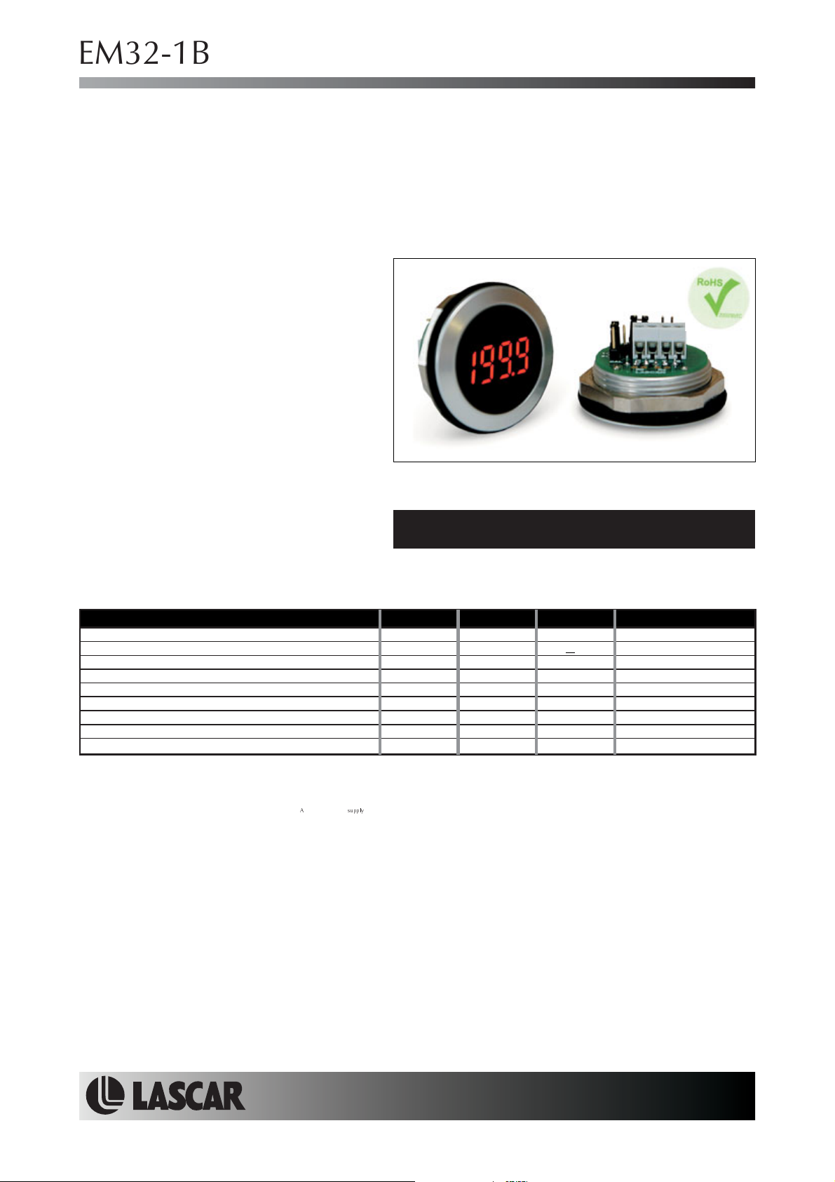
EM32-1B-LED
Round Hole Mounting LED Voltmeter
PRODUCT DESCRIPTION
The EM32-1B-LED isa3½digitLEDvoltmeterwhichis designed to be panel mounted in most low and medium
volume applications. The meter features 8mmdigitheight,3decimalpoints,auto-polarity, auto-zero, 200mVfull
scale reading and a low current consumption. This product is designedsonosolderingisrequired.Connectionis
via screw terminals, and options are selected via jumper links. The module features a round metal bezel,
requiring a 32.5mm (1.28") diametercut-out. It is securedwiththenutprovided.Protection from thefront to IP 67
/ NEMA 4Xstandards is achieved by placingthe rubber seal between the moduleand panel during assembly.
FEATURES
•8
mm (0.31") Digit Height
• 200mV d.c. Full Scale Reading
• 50mA @ 5Vd.c. Operation
•
Auto-zero and Auto-polarity
• Selectable
• Requires 32.5mm (1.28") Diameter Cut-out
• IP67 / NEMA 4X Protected
Decimal Points
TYPICAL APPLICATIONS
• Panel Mount Instrumentation
• Process & Control
• Automotive
ORDERING INFORMATION
Stock Number
Standard Meter EM32-1B-LED
ELECTRICAL SPECIFICATIONS
Specification Min. Typ. Max. Unit
Accuracy (overall error) * 0.1 % (±1 count)
Linearity 1 count
Sample rate 2.5 samples/sec
Operating temperature range 0 50 °C
Temperature stability 150 ppm/°C
Warm-up time 10 minutes
Supply voltage (V+ to V-) 4.75
Supply current 50 100 mA
Input leakage current (Vin = 0V) 1 10 pA
* To ensure maximum accuracy, re-calibrate periodically.
** Operation of the meter beyond the maximum supply voltage rating may cause permanent damage to the meter.
Unless otherwise noted,specifications apply atT =25°C, V =5Vd.c. and aretested with themodule configured forfloating input mode.
A supply
5 5.25 V d.c.
+
SAFETY
To comply with the Low Voltage Directive (LVD 93/68/EEC), input voltages to the module’s pinsmust notexceed
60Vdc. The user must ensure thatthe incorporationof the panel meter into the user’s equipmentconforms tothe
relevant sections of BS EN 61010 (Safety Requirements for Electrical Equipment for Measuring, Control and
Laboratory Use).
LASCAR ELECTRONICS LTD.
MODULE HOUSE,
WHITEPARISH,
WILTSHIRE SP5 2SJ,
UK
TEL: +44 (1794) 884567
FAX: +44 (1794) 884616
E-mail: [email protected]
Specifications liable to change without prior warning EM32-1B-LED Issue 6 06/2010 S.L. Applies to EM32-1B-LED/1
LASCAR ELECTRONICS INC.
4258 WEST 12th STREET,
ERIE,
PA 16505,
USA
TEL: +1 (814) 835 0621
FAX: +1 (814) 838 8141
E-mail: [email protected]
LASCAR ELECTRONICS (HK) LTD.
8th FLOOR, CHINA AEROSPACE CENTRE,
143 HOI BUN ROAD,
KWUN TONG, KOWLOON,
E- mail: [email protected]
HONG KONG
TEL: +852 2389 6502
FAX: +852 2389 6535
Page4of4Page 4 of 4
www.lascarelectronics.com No: 716 - Page 1 of 4
Page 2
EM32-1B-LED
Round Hole Mounting LED Voltmeter
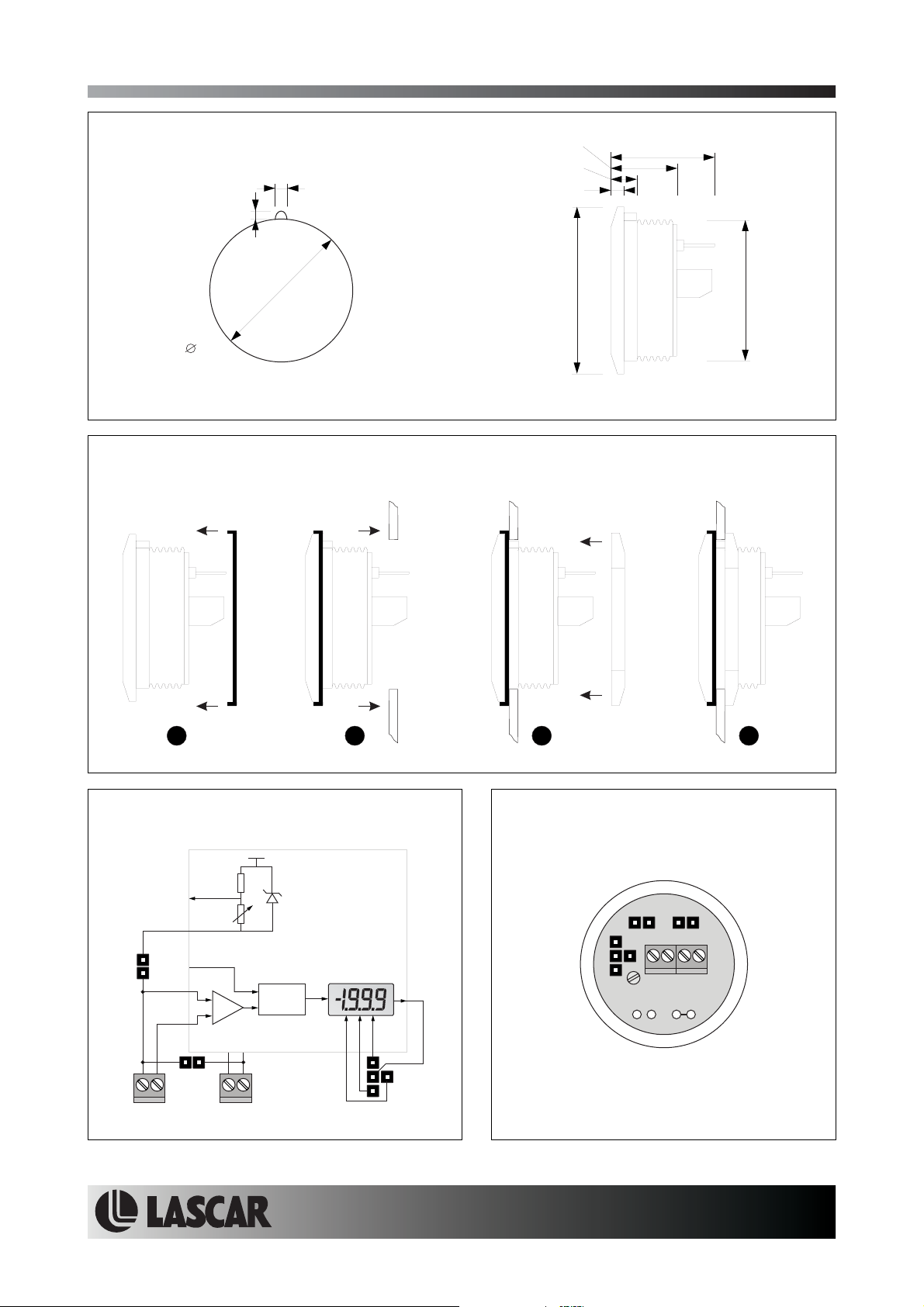
DIMENSIONS
All dimensions in mm (inches)
1.7 (0.07)
32.5
(1.28)
Panel cut-out
PANEL MOUNTING
1.5 (0.06)
15.0 (0.59)
5.5 (0.22)
3.0 (0.12)
38.0 (1.5)
23.5 (0.93)
32.0 (1.26)
23 41
FUNCTIONAL BLOCK DIAGRAM
V+
RHI
COM
J2
RLO
ILO
IHI
+
_
V+ V-
J1
ILO IHI V+ V-
Specifications liable to change without prior warning EM32-1B-LED Issue 6 06/2010 S.L. Applies to EM32-1B-LED/1
CAL
A/D
Vref
1
DP 3 2 1
8
CONNECTIONS (rear view)
J2J1
0V
V+
IHI
ILO
CAL
RB
RA
Page4of4Page 4 of 4
www.lascarelectronics.com No: 716 - Page 2 of 4
Page 3
EM32-1B-LED
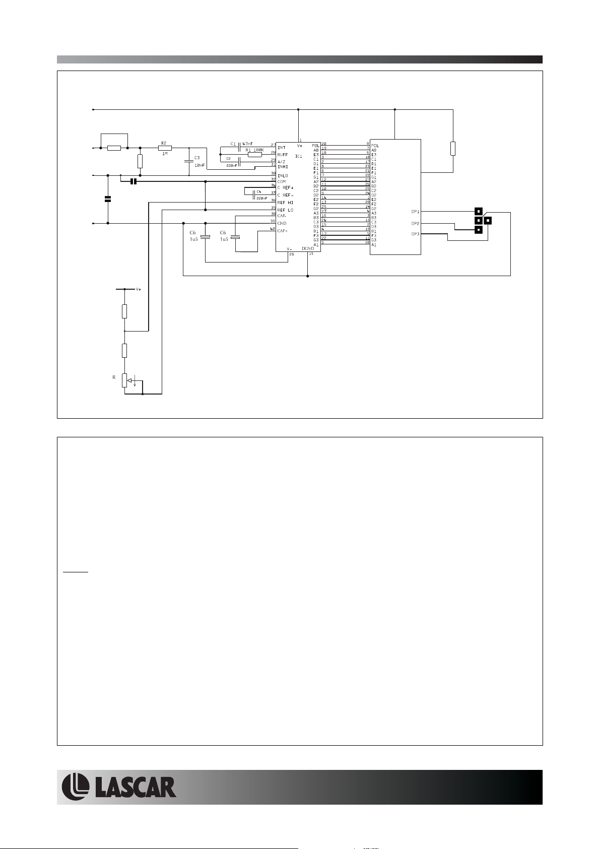
CIRCUIT DIAGRAM
V+
Round Hole Mounting LED Voltmeter
IHI
ILO
0V
Ra
J2
R4
100k
R5
3k0
R6
1k0
R7
Rb
J1
C6
C6
1u5
1u5
CAP-
GND
CAP+
MAX140
DGND
21
ANODE
DP1, DP2, DP3
DISPLAY
1k5
SCREW TERMINAL FUNCTIONS
0V Negative power supply to the meter.
V+ Positive power supply tothe meter (+5V nom).
IHI Positivemeasuring input.
IHI must be no closer than 1.5V to either the positiveorthe internal negative supply.
ILO Negativemeasuring input.
ILO must be no closer than 1.5V to either the positiveorthe internal negative supply.
Note:
Internal negative supply. This is generated from the supply voltage between V+ and 0V, and is negative
with respect to 0V.
For example: if V+ = +5V (with respect to 0V), then the allowable common mode input range is from
(V+ - 1.5V) to (V- + 1.5V) or from 3.5V to -3.5V with respect to the 0V powersupply connection.
JUMPER LINKS
J1 ConnectsILO to COM, when jumper link is fitted.
J2 Connects ILO to0V, when jumper link is fitted.
Specifications liable to change without prior warning EM32-1B-LED Issue 6 06/2010 S.L. Applies to EM32-1B-LED/1
Page4of4Page 4 of 4
www.lascarelectronics.com No: 716 - Page 3 of 4
Page 4
EM32-1B-LED
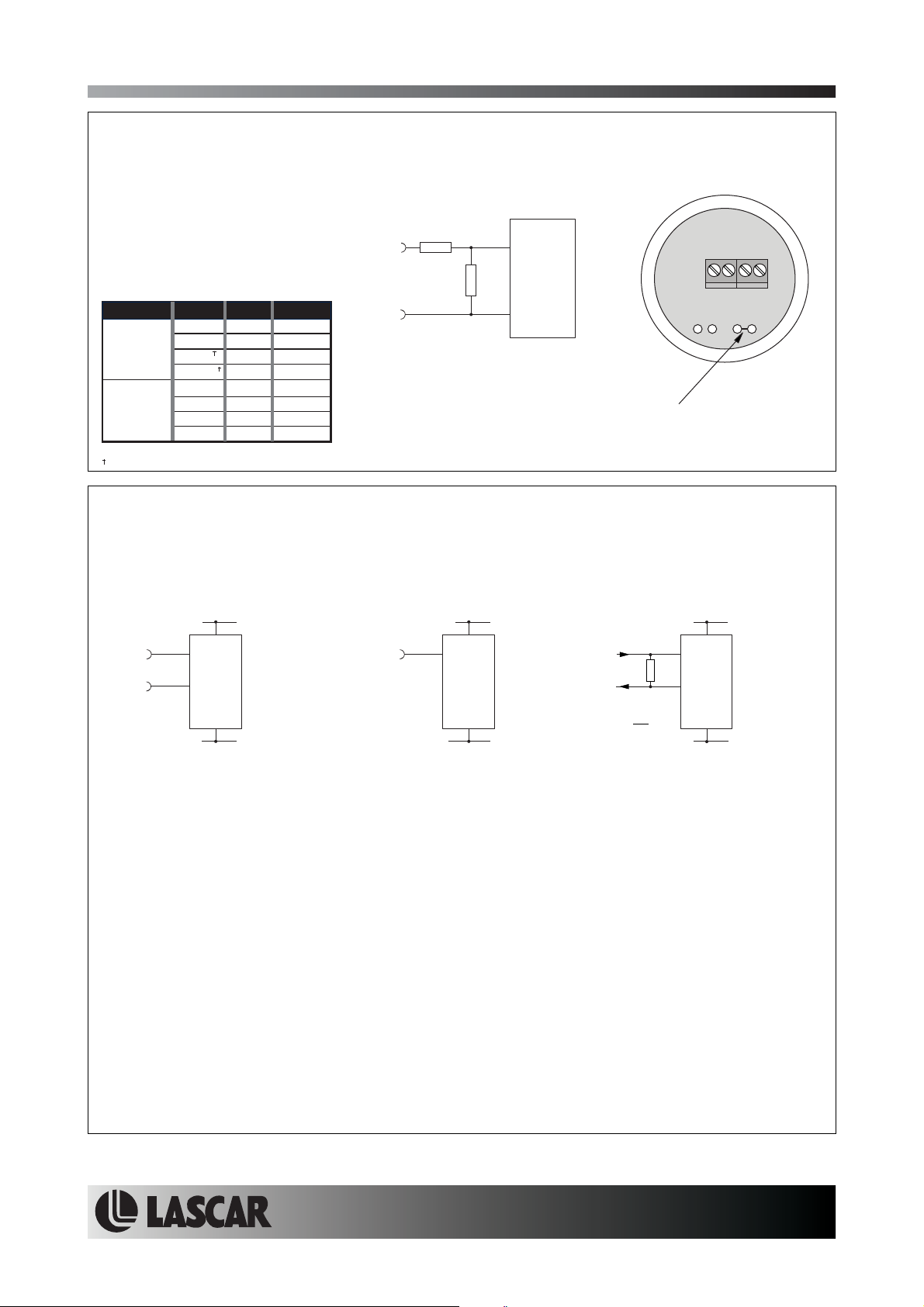
SCALING
Two resistors Ra and Rb may be
used to alter the full scale reading
(FSR) of the meter - see table. Cut
the PCB track across Ra before
fitting Ra. The meter will have to
be re-calibrated by adjusting the
calibration potentiometer on the
rear of themodule.
+
Vin or inI
Round Hole Mounting LED Voltmeter
Ra
Rb
IHI
EM32-1B-LED
FSR Ra Rb
2V 910k 100k
Voltage
Vin 200V 1M 1k
Current
Iin 20mA 0R 10R
*Ensure that Ra is rated for high voltage use.
Must use external scaling resistors (Do not cut track across Ra).
20V 1M 10k
2000V* 1M 100R
200 A 0R 1k
m
2mA 0R 100R
200mA 0R 1R
-
ILO
RA
RB
Cut the PCB track across Ra
before fitting Ra.
APPLICATIONS
Do not connect more than one meter to the same power supply if the meters cannot use the same signal
ground. Taking any inputbeyond the power supply railswill damage the meter.
+4.75 to +5.25V
V+
0V
0V
+
±200mV
-
IHI
ILO
+4.75 to +5.25V +4.75 to +5.25V
V+
+
0V
0V
V+
IHI
0V
0V
R = 0.2
IHI
R
ILO
I
FSR
Measuring an input voltage referenced
to a floating supply, i.e. the input
voltage and the meter's power supply
are isolated from each other.
Ensure Jumper link J1 is fitted.
Ensure Jumper link J2 is not fitted.
Specifications liable to change without prior warning EM32-1B-LED Issue 6 06/2010 S.L. Applies to EM32-1B-LED/1
Measuring a single ended input
voltage referenced to supply, i.e. the
input voltage and the meter's power
supply share the same 0V rail.
Ensure Jumper link J1 is not fitted.
Ensure Jumper link J2 is fitted.
Measuring current.
The meter's supply is isolated
from the current being measured.
Ensure Jumper link J1 is fitted.
Ensure Jumper link J2 is not fitted.
Page4of4Page 4 of 4
www.lascarelectronics.com No: 716 - Page 4 of 4
 Loading...