

DPM 942-FPSI
4-20mA Loop Meter with
ORDERING INFORMATION
Programmable Backlighting
FEATURES
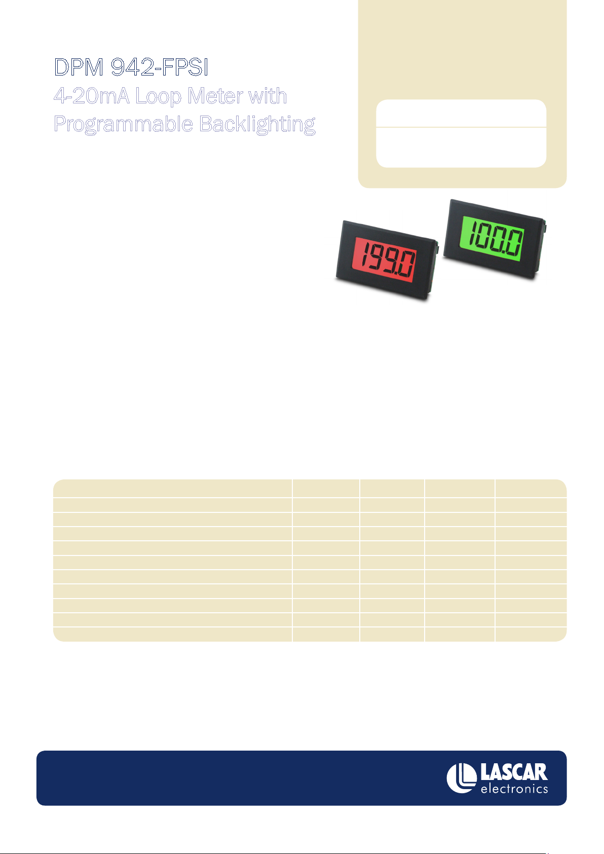
• 19mm (0.75”) digit height
• Dual colour backlight with programmable status indication
• Open collector outputs that mirror the backlight status (with
inverted output option)
• 5V supply voltage
• 4–20mA measurement range
The DPM 942-FPSI is a 3 ½ digit LCD current loop meter that can also be used for dual colour go-stop status indication. This
functionality is ideal for simplifying monitoring applications, where an operator needs to know the status of the equipment at a glance.
During standard operation the backlight is green, however if the reading goes beyond the user programmable thresholds, the display will
turn red. Three open collector outputs are included, that indicate high, ok and low conditions. Both the backlight colour and outputs can
be inverted.
Standard Instrument
(panel meter, xing
kit, data sheet)
DPM 942-FPSI
Module setup is a simple operation using an eight-way DIP switch and two push buttons. No special tools or equipment are required.
SPECIFICATIONS
Accuracy (overall error)
Linearity
Sample rate
Hysteresis (high and low thresholds)
Operating temperature range
Temperature stability
Supply voltage
Supply current (not including backlight)
Backlight voltage
Backlight current
Minimum
0 (32)
4.5
Typical
0.05
3
2
100
5
1
5
Maximum
0.1
±1
50 (122)
5.5
40
Unit
% (±1 count)
count
samples/second
counts
°C (°F)
ppm/°C
V
mA
V
mA
www.lascarelectronics.com
Specications liable to change without prior warning Issue 3 04/11 S.L Applies to DPM 942-FPSI Page 1 of 5
DPM 942-FPSI
4-20mA Loop Meter with Programmable Backlighting
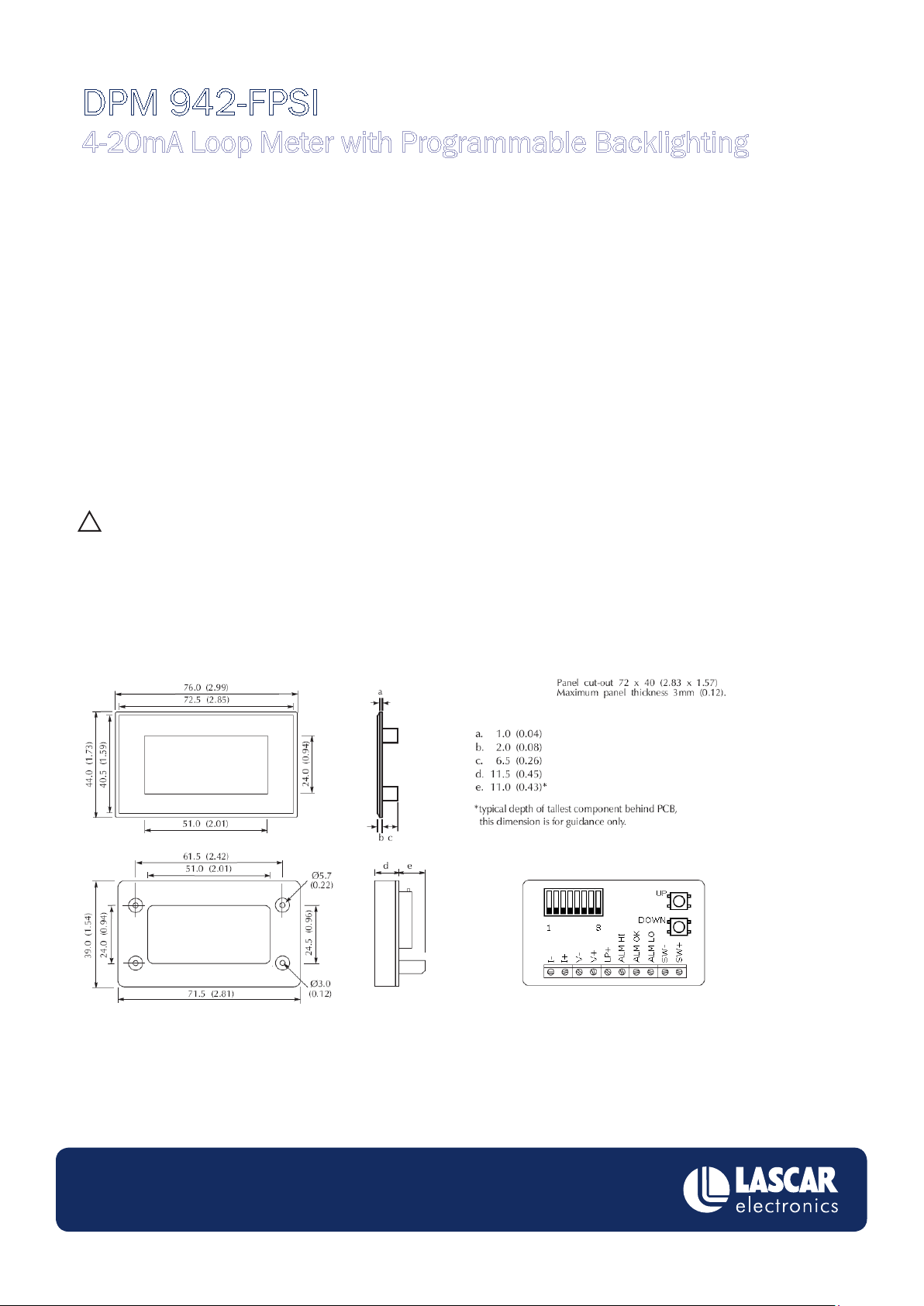
PIN FUNCTIONS
1. I- Negative current loop input
2. I+ Positive current loop input
3. V- Negative supply connection
4. V+ Positive supply connection
5. LP+ Positive backlight connection
6. ALM HI Open collector alarm output. Goes low when the high threshold of the module has been passed.
7. ALM OK Open collector alarm output. Goes low when the module is measuring a signal between the high and low thresholds.
8. ALM LO Open collector alarm output. Goes low when the lower threshold of the module has been passed.
9. SW- Negative switch input for ashing backlight acknowledgement.
10. SW+ Positive switch input for ashing backlight acknowledgement.
LCD SYMBOLS
‘Err’ Return dip switches 1 to 5 to the off position. Only 1 of theses switches may be in the on position at a time.
! The unit is in set-up mode. To view the measured signal, ensure switches 1 to 5 are in the off position.
DIMENSIONS
All dimensions in mm (inches)
www.lascarelectronics.com
Specications liable to change without prior warning Issue 3 11/10 S.L Applies to DPM 942-FPSI Page 2 of 5

DPM 942-FPSI
4-20mA Loop Meter with Programmable Backlighting
DIP SWITCH CONFIGURATION
1. Enter offset calibration mode
ON
1 2 3 4 5 6
7 8
OFFSET AND SPAN CALIBRATION
Calibration is performed in two steps. The rst step is to adjust the offset value. The second is to adjust the span.
To adjust the offset, move DIP 1 to the ‘on’ position and input a known constant current (typically 4mA). By default, 000 will be displayed. The
user can then use the 2 push buttons mounted on the rear of the device to adjust the value on the display. Pressing the ‘up’ button once will
increase the value on the LCD by one count. Pressing the ‘down’ button once will decrease the value on the LCD by one count.
If either button is held down, the value will continuously change until the button is released again. When the desired value is on the
display, return DIP 1 to the ‘off’ position.
2. Enter span calibration mode
3. Enter high threshold setup mode
4. Enter low threshold setup mode
5. Enter decimal place setup mode
6. Invert alarm operation
7. Invert outputs
8. Select backlight supply
To adjust the span, move DIP 2 to the ‘on’ position and input a known current (typically 20mA). By default 1000 will be displayed. The value
can then be adjusted in the same way as the offset.
THRESHOLD SETUP
There are two independent thresholds on the unit which control the backlight colour and open-collector outputs. The high threshold is trig-
gered when exceeded by the input signal and the low threshold is triggered when the input signal drops below it. Both thresholds can be set,
enabled and disabled independently.
By default the backlighting is green when an input is normal and red when the input exceeds a threshold (see INVERT BACKLIGHT COLOURS
for more information). The thresholds can be set to any value between -1999 and 1999, however, it is not possible to assign a value to the
low threshold which exceeds that of the high threshold and vice versa. In addition to numerical values, it is also possible to set both values to
an ‘over range’ condition. This will only trigger the backlight when the input goes beyond a value that can be displayed.
To adjust the threshold calibration:
First select a position on the miniature DIP switch, mounted on the reverse of the module.
• Moving position 3 to ‘on’ will display the high threshold value
• Moving position 4 to ‘on’ will display the low threshold value
When a threshold is selected, it can then be adjusted using the two push buttons mounted on the rear of the device. The thresholds are
adjusted as shown overleaf.
www.lascarelectronics.com
Specications liable to change without prior warning Issue 3 11/10 S.L Applies to DPM 942-FPSI Page 3 of 5

DPM 942-FPSI
4-20mA Loop Meter with Programmable Backlighting
High threshold:
Press button
Default
threshold off.
Display shows
OFF
Press ‘down’
button once to
enable overrange.
Display shows OL
Press ‘down’
button once to
show 1999
once for each
digit of change
(down to reduce
value, up to
increase value)
Low threshold:
Default
threshold off.
Display shows
OFF
When the DIP switches are returned to the ‘on’ positions the display shows the current loop value, as dened by the offset and span settings
previously programmed.
In standard operation, the high and low thresholds have a hysteresis value of two counts. This only applies when going from an alarm
condition to a non-alarm condition (i.e. the signal has to go at least 2 counts into the non-alarm condition before the backlight will return to
green). This is to prevent ickering and unnecessary repeat alarms.
Press ‘up’ button
once to enable
underrange.
Display shows UL
Press ‘up’
button once to
show -1999
Press button
once for each
digit of change
(down to reduce
value, up to
increase value)
DECIMAL PLACE AND LEADING ZERO SELECTION
The position of the decimal point and number of leadings zeros is changed by setting DIP switch ‘5’ to the ‘on’ position and using the up and
down buttons on the rear of the module. The decimal point has three possible positions as well as an ‘off’ option. The leading zeros can be
set to one (the user can select the decimal point position and the leading zero will move accordingly) or ‘all on’. Return DIP switch ‘5’ to the
‘on’ position before installing the module in the application.
INVERT ALARMS
The red and green backlighting and three alarm outputs can be inverted by moving DIP switch 6 to the ‘on’ position.
INVERT OUTPUTS
Changing DIP switch 7 to ‘on’ inverts the three alarms outputs. i.e. the output that was previously on is now off, and the two outputs that were
previously off are now on. This can be used in conjuction with DIP switch 6 to set the outputs back to the ‘original’ position.
SELECT BACKLIGHT SUPPLY
V+ and LP+ share a common ground (V-). By default, V+ and LP+ are not connected. Moving DIP switch 8 to the ‘on’ position connects LP+
directly to V+, removing the need for a separate supply.
FLASHING BACKLIGHT
By default, the backlight will ash red when an alarm threshold is exceeded. Temporarily connecting the SW+ and SW- inputs will stop the
ashing (the backlight will remain red however). The backlight will not ash again, until the alarm has cleared (i.e. returned to green) and
another threshold is exceeded.
Connecting a wire link permanently between SW+ and SW- will disabled ashing and the backlight will remain as a solid colour.
www.lascarelectronics.com
Specications liable to change without prior warning Issue 3 11/10 S.L Applies to DPM 942-FPSI Page 4 of 5

DPM 942-FPSI
Measuring a current loop. The meter power
supply should be isolated from the 4-20mA
transmitter power supply
Using an external LED as a high alarm and a switch
to acknowledge the alarm (to stop it flashing)
2
1
3
V-
I+
LP+
I-
V +
V-
4
5
V +
4-20mA
Transmitter
I+
I-
2
1
3
V-
I+
LP+
I-
V +
V-
4
5
4-20mA
Transmitter
I+
I-
V +
R
ALM HI
SW+
SW-
6
9
10
4-20mA Loop Meter with Programmable Backlighting
FACTORY RESET
Module calibration can be reset to the factory default by moving all 8 dip switches to ‘on’ and powering up the unit. The LCD will display
4 dashes when the reset is complete. Moving all the dip switches back to the ‘off’ position will return the module to the operating mode.
SAFETY
To comply with the Low Voltage Directive (LVD 93/68/EEC), input voltages to the module’s pins must not exceeD 60V d.c. If voltages to the
measuring inputs do exceed 60V d.c., then t scaling resistors externally to the module. The user must ensure that the incorporation of the
DPM into the user’s equipment conforms to the relevant sections of BS EN 61010 (Safety Requirements for Electrical Equipment for
Measuring, Control and Laboratory Use).
VARIOUS OPERATION MODES
Module House
Whiteparish, Salisbury
Wiltshire. SP5 2SJ
UK
T +44 (1794) 884567
F +44 (1794) 884616
E sales@lascar.co.uk
Specications liable to change without prior warning Issue 4 05/1 N.J.H Applies to DPM 942-FPSI Page 5 of 5
425. West 12th Street
Erie
PA 16505
USA
T +1 (814) 835 0621
F +1 (814) 838 8141
E us-sales@lascarelectronics.com
www.lascarelectronics.com
8th Floor, China Aerospace Centre
143 Hoi Bun Road
Kwun Tong, Kowloon
HONG KONG
T +852 2389 6502
F +852 2389 6535
E saleshk@lascar.com.hk
 Loading...